EP2484869A2 - Entretoise à profil aérodynamique pour diffuseur de gaz d'échappement à faible solidité - Google Patents
Entretoise à profil aérodynamique pour diffuseur de gaz d'échappement à faible solidité Download PDFInfo
- Publication number
- EP2484869A2 EP2484869A2 EP12153516A EP12153516A EP2484869A2 EP 2484869 A2 EP2484869 A2 EP 2484869A2 EP 12153516 A EP12153516 A EP 12153516A EP 12153516 A EP12153516 A EP 12153516A EP 2484869 A2 EP2484869 A2 EP 2484869A2
- Authority
- EP
- European Patent Office
- Prior art keywords
- strut
- leading edge
- edge
- airfoil
- tail
- Prior art date
- Legal status (The legal status is an assumption and is not a legal conclusion. Google has not performed a legal analysis and makes no representation as to the accuracy of the status listed.)
- Withdrawn
Links
- 239000007789 gas Substances 0.000 description 16
- 238000009792 diffusion process Methods 0.000 description 6
- 239000000446 fuel Substances 0.000 description 6
- 230000003247 decreasing effect Effects 0.000 description 4
- 239000000463 material Substances 0.000 description 3
- 230000003068 static effect Effects 0.000 description 3
- 238000002485 combustion reaction Methods 0.000 description 2
- 230000004075 alteration Effects 0.000 description 1
- 239000000567 combustion gas Substances 0.000 description 1
- 239000000203 mixture Substances 0.000 description 1
- 238000006467 substitution reaction Methods 0.000 description 1
Images


Classifications
-
- F—MECHANICAL ENGINEERING; LIGHTING; HEATING; WEAPONS; BLASTING
- F01—MACHINES OR ENGINES IN GENERAL; ENGINE PLANTS IN GENERAL; STEAM ENGINES
- F01D—NON-POSITIVE DISPLACEMENT MACHINES OR ENGINES, e.g. STEAM TURBINES
- F01D9/00—Stators
- F01D9/06—Fluid supply conduits to nozzles or the like
- F01D9/065—Fluid supply or removal conduits traversing the working fluid flow, e.g. for lubrication-, cooling-, or sealing fluids
-
- F—MECHANICAL ENGINEERING; LIGHTING; HEATING; WEAPONS; BLASTING
- F01—MACHINES OR ENGINES IN GENERAL; ENGINE PLANTS IN GENERAL; STEAM ENGINES
- F01D—NON-POSITIVE DISPLACEMENT MACHINES OR ENGINES, e.g. STEAM TURBINES
- F01D25/00—Component parts, details, or accessories, not provided for in, or of interest apart from, other groups
- F01D25/16—Arrangement of bearings; Supporting or mounting bearings in casings
- F01D25/162—Bearing supports
-
- F—MECHANICAL ENGINEERING; LIGHTING; HEATING; WEAPONS; BLASTING
- F01—MACHINES OR ENGINES IN GENERAL; ENGINE PLANTS IN GENERAL; STEAM ENGINES
- F01D—NON-POSITIVE DISPLACEMENT MACHINES OR ENGINES, e.g. STEAM TURBINES
- F01D5/00—Blades; Blade-carrying members; Heating, heat-insulating, cooling or antivibration means on the blades or the members
- F01D5/12—Blades
- F01D5/14—Form or construction
- F01D5/141—Shape, i.e. outer, aerodynamic form
-
- F—MECHANICAL ENGINEERING; LIGHTING; HEATING; WEAPONS; BLASTING
- F01—MACHINES OR ENGINES IN GENERAL; ENGINE PLANTS IN GENERAL; STEAM ENGINES
- F01D—NON-POSITIVE DISPLACEMENT MACHINES OR ENGINES, e.g. STEAM TURBINES
- F01D9/00—Stators
- F01D9/02—Nozzles; Nozzle boxes; Stator blades; Guide conduits, e.g. individual nozzles
- F01D9/04—Nozzles; Nozzle boxes; Stator blades; Guide conduits, e.g. individual nozzles forming ring or sector
-
- F—MECHANICAL ENGINEERING; LIGHTING; HEATING; WEAPONS; BLASTING
- F05—INDEXING SCHEMES RELATING TO ENGINES OR PUMPS IN VARIOUS SUBCLASSES OF CLASSES F01-F04
- F05D—INDEXING SCHEME FOR ASPECTS RELATING TO NON-POSITIVE-DISPLACEMENT MACHINES OR ENGINES, GAS-TURBINES OR JET-PROPULSION PLANTS
- F05D2250/00—Geometry
- F05D2250/10—Two-dimensional
Definitions
- the subject matter described herein relates to gas turbines, and, more specifically, to strut airfoils in a diffuser of a gas turbine.
- a gas turbine engine includes a compressor having a number of compressor blades disposed on a shaft, with the compressor blades and shaft configured to define a decreasing volume. Airflow ingested into the gas turbine is compressed as it passes through the compressor. A number of combustors are disposed downstream of the compressor, where air and fuel are mixed and the fuel is ignited. A multi-stage turbine is disposed downstream of the combustors.
- First stages of the multi-stage turbine are defined by a number of turbine vanes disposed on the shaft of the compressor.
- Final stages of the multi-stage turbine are defined by a number of turbine vanes disposed on an output drive shaft, which rotates independently of the shaft of the compressor.
- the heated compressed air flow from the combustors turns the multi-stage turbine.
- the rotation of the first stages of the multi-stage turbine rotates the shaft of the compressor.
- the rotation of the final stages of the multi-stage turbine rotates the output drive shaft, which in turn drives a generator.
- a diffuser is disposed aft of the final stages of the multi-stage turbine and is configured to decelerate the exhaust flow and convert dynamic energy to a static pressure rise.
- the diffuser includes a number of struts that contain a support strut encased by a strut airfoil. The struts turn a flow from the multi-stage turbine towards the axial direction when the gas turbine engine is operated within a desired performance range.
- Exhaust diffusers with 4 to 6 struts often do not have enough solidity to straighten the gas flow. Instead, the 4 to 6 struts amplify the swirl, thereby creating bigger aerodynamic blockage and losses in the high mach number region.
- a strut cover is needed that guides the swirl, diffuses the flow of gas on the pressure side, reduces aerodynamic blockage, improves overall performance, or avoids strut wake creation.
- the invention resides in a strut airfoil for use in an exhaust diffuser, the strut airfoil has a curved leading edge, a curved tail edge with a smaller radius than the leading edge, and two surfaces that connect the leading edge and the tail edge.
- the leading edge and tail edge are offset so that one of the surfaces connecting the leading edge with the tail edge is substantially linear for more than 50% of the distance from the leading edge to the tail edge, and the second surface is tapered over a portion of the distance from the leading edge to the tail edge.
- the invention resides in a gas turbine, having moving blades attached to a rotor, an exhaust differ comprising a strut, and a strut airfoil as described above.
- the exhaust diffuser takes up combustion gas from the moving blades; the strut supports the rotor, and the strut airfoil is arranged around the strut.
- the strut airfoil has a curved leading edge, a curved tail edge with a smaller radius than the leading edge, and two surfaces that connect the leading edge and the tail edge.
- the leading edge and tail edge are offset so that one of the surfaces connecting the leading edge with the tail edge is substantially linear for more than 50% of the distance from the leading edge to the tail edge, and the second surface is tapered over a portion of the distance from the leading edge to the tail edge.
- the curved leading edges of the strut airfoils described herein are of a different size than the curved tail edges.
- the curved leading edge has a larger radius than the curved tail edge.
- the curves of the leading edges and tail edges may also be non-circular.
- the curves may be elliptical, parabolic, asymmetric, etc. If the curves of the leading edge and tail edge are non-circular, either the major or minor radii should be used consistently to compare the sizes of the leading edges and tail edges.
- the curved leading edge and curved tail edge when viewed in cross-section, are offset.
- the leading edge and tail edge are offset so that when a chord is drawn that bisects each curved edge, the surface areas of the cross-section on either side of the chord are unequal.
- one of the surfaces connecting the leading edge and the tail edge may be substantially linear for more than 50% of the distance from the leading edge to the tail edge. In certain embodiments, one of the surfaces connecting the leading edge and the tail edge may be substantially linear for more than 55% of the distance from the leading edge to the tail edge. In certain embodiments, one of the surfaces connecting the leading edge and the tail edge may be substantially linear for more than 65% of the distance from the leading edge to the tail edge. In certain embodiments, one of the surfaces connecting the leading edge and the tail edge may be substantially linear for more than 75% of the distance from the leading edge to the tail edge. In certain embodiments, one of the surfaces connecting the leading edge and the tail edge may be substantially linear for more than 85% of the distance from the leading edge to the tail edge. In certain embodiments, one of the surfaces connecting the leading edge and the tail edge may be substantially linear for more than 95% of the distance from the leading edge to the tail edge.
- the distance from the leading edge to the tail edge may be measured from where the surface connects to the leading edge to where it connects to the tail edge. In other embodiments, the distance may represent the chord of the strut airfoil. Typically, the chord is a longitudinal line that bisects each curved edge.
- the surfaces connecting the leading edge to the tail edge are substantially parallel proximal to the leading edge.
- the second surface is parallel to the first surface for at least 30% of the distance from the leading edge to the tail edge.
- the second surface is parallel to the first surface for at least 40% of the distance from the leading edge to the tail edge.
- the second surface is parallel to the first surface for at least 50% of the distance from the leading edge to the tail edge.
- the second surface is tapered over a portion of the distance from the leading edge to the tail edge.
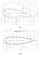
- strut airfoil described herein is illustrated in cross-section in Fig. 1a . Also included in Fig. 1b , for comparison, is the depiction of a cross-section of a strut airfoil from the prior art. Whereas the strut airfoil from the prior art is symmetric, the strut airfoils described herein are generally asymmetric.
- the strut airfoil when viewed in cross-section, has a curved leading edge 1, a curved tail edge 2, and two surfaces that connect the leading edge and the tail edge.
- first surface 3 is substantially linear for more than 50% of the distance from the leading edge to the tail edge.
- second surface 4 is tapered over a portion of the distance from the leading edge 1 to the tail edge 2.
- the curved leading edge 1 and the curved tail edge 2 are of different size.
- the curved leading edge 1 has a larger radius than the curved tail edge 2.
- FIG. 2 illustrates a cross-sectional view of the strut airfoil.
- the strut airfoil has a curved leading edge 1 that has a larger radius than the curved tail edge 2.
- the leading edge 1 and tail edge 2 are connected by a first surface 3 that is substantially linear for more than 50% of the distance between the leading edge and tail edge; and a second surface 4 that is tapered over a portion of the distance from the leading edge to the tail edge.
- Fig. 9 is a side-view of the strut airfoil, and shows one of the surfaces 1 connecting the leading edge 2 with the tail edge 3.
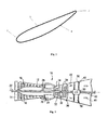
- a heavy-duty gas turbine engine is shown generally at 10.
- the gas turbine engine 10 has a generally annular shape defined by an outer turbine casing 12.
- An inlet 14 is defined at one end of the gas turbine engine 10.
- the inlet 14 leads to a compressor 16 that is defined by and a number of compressor blades 18 disposed within the casing 12.
- the compressor blades 18 are disposed on a shaft 20 that extends along a centerline 22 of the casing 12, with the compressor blades 18 and shaft 20 configured to define a decreasing volume.
- Airflow ingested into the gas turbine engine 10 at the inlet 14 is compressed as it passes through the compressor 16.
- a number of combustors 24 are disposed downstream of the compressor 16, and are positioned axially about the shaft 20.
- the combustors 24 have a premixing chamber and a combustion chamber (both of which are not shown).
- the airflow from the compressor 16 is ingested through entry ports 26 into the premixing chamber.
- fuel from a fuel inlet 28 is delivered into the premixing chamber.
- a multi-stage turbine 30 is disposed within the casing 12 downstream of the combustors 24.
- First stages 32 of the multi-stage turbine 30 are defined by a plurality of turbine vanes 34 disposed on the shaft 20.
- Final stages 36 of the multi-stage turbine 30 are defined by a plurality of turbine vanes 38 disposed on an output drive shaft 40.
- the output drive shaft 40 also extends along the centerline 22 of the casing 12, as it is axially aligned with the shaft 20, but rotates independently thereof.
- the heated compressed air flow from the combustors 24 turns the multi-stage turbine 30.
- a diffuser 42 is disposed aft of the final stages 36 of the multi-stage turbine 30 and is configured to decelerate the exhaust flow and convert dynamic energy to a static pressure rise.
- the diffuser 42 includes a number of turning struts 50 that contain a support strut encased by an aerodynamic faring.
- the struts 50 turn a flow 44 from the multi-stage turbine 30 towards the axial direction, resulting in a flow 46, when the gas turbine engine 10 is operated within a designed performance range.
- the struts 50 are disposed circumferentially within the annulus of the diffuser 42.
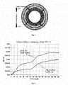
- the number of struts in the exhaust diffusers described herein may be 10 or fewer. In certain embodiments, the exhaust diffuser contains 8 or fewer struts. In certain embodiments, the exhaust diffuser contains 6 or fewer struts. In one embodiment, the exhaust diffuser contains 4 struts. A 4-strut setup is illustrated in Fig. 4 , which depicts four struts 1.
- the struts and strut airfoils described herein may be fabricated from any acceptable materials, including those known in the prior art. In certain embodiments, the quality or strength of the materials used to fabricate the struts or strut airfoils may reduce the number of struts needed in the gas turbines disclosed herein.
- the strut airfoils described herein offer several advantages over the strut airfoils disclosed in the prior art.
- the prior art strut airfoils such as the symmetric airfoil depicted in Fig. 1b , perform especially poorly in exhaust diffusers with 4 to 6 struts, because the struts do not have enough solidity to straighten the air flow. Instead, the prior art strut airfoils amplify the swirl, thereby creating bigger aerodynamic blockage and losses in the high mach number region.
- the strut airfoils described herein guide the swirl and diffuse the flow on the pressure side.
- the strut airfoils reduce aerodynamic blockage, improve performance, and avoid strut wake creation.
- Fig. 5 illustrates the performance of the prior art strut airfoil from Fig. 1b in an exhaust diffuser containing 4 struts. This figure depicts the changes in velocity and pressure caused by the prior art strut airfoils.
- Fig. 5 offers a cross-sectional view of the pressure drop in the exhaust diffuser that is caused by the prior art strut airfoil. The figure depicts four, large low pressure zones that correspond roughly with the positions of the four struts.
- FIG. 6 illustrates the performance of an embodiment of the strut airfoil described herein.
- This figure depicts the changes in velocity and pressure caused by the asymmetric strut airfoil depicted in Fig. 1a .
- Fig. 6 shows a cross-sectional view of the pressure drop in the exhaust diffuser that is caused by one embodiment of the strut airfoil described herein and depicted in Fig. 1a .
- the four low pressure zones in Fig. 6 that correspond roughly with the positions of the four strut airfoils are much smaller than those appearing in Fig. 5 .
- Fig. 7 also illustrates the differences in pressure loss introduced by the prior art strut airfoil and one embodiment of the strut airfoil according to this disclosure, which are depicted in Figs. 1a and 1b .
- the pressure drop caused by the strut airfoil of Fig. 1a is generally lower than the pressure drop caused by the prior art strut airfoil, depicted in Fig. 1b .
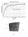
- Fig. 8 illustrates the performance of the strut airfoil of Fig. 1a , compared with the prior art strut airfoil, depicted in Fig. 1b .
- Fig. 8 shows that the performance of the presently-described strut airfoil is superior, especially from approximately 20 to approximately 130. This region of improved performance corresponds with the location of the strut and strut airfoil in the exhaust diffuser.
- Fig. 10 illustrates the flow diffusion on the prior art strut airfoil depicted in Fig. 1b , where the longitudinal length of the strut airfoil is 40.
- Fig. 11 illustrates the flow diffusion on the strut airfoil described herein, which is also depicted in Fig. 1a and Fig. 9 , where the longitudinal length of the strut airfoil is 40 inches.
- Fig. 9 illustrates the longitudinal lengths of 40 inches 5 and 62 inches 4. Comparing Fig. 10 with Figs. 11 demonstrates the improved performance of the strut airfoils described herein: the flow diffusion in Fig. 11 is above 0.9 at the same location on the strut airfoil. Due to the improved design of the strut airfoils described herein, there is a higher static pressure in the diffuser.
Landscapes
- Engineering & Computer Science (AREA)
- Mechanical Engineering (AREA)
- General Engineering & Computer Science (AREA)
- Physics & Mathematics (AREA)
- Fluid Mechanics (AREA)
- Structures Of Non-Positive Displacement Pumps (AREA)
- Turbine Rotor Nozzle Sealing (AREA)
Applications Claiming Priority (1)
| Application Number | Priority Date | Filing Date | Title |
|---|---|---|---|
| US13/021,136 US20120198810A1 (en) | 2011-02-04 | 2011-02-04 | Strut airfoil design for low solidity exhaust gas diffuser |
Publications (2)
| Publication Number | Publication Date |
|---|---|
| EP2484869A2 true EP2484869A2 (fr) | 2012-08-08 |
| EP2484869A3 EP2484869A3 (fr) | 2014-09-03 |
Family
ID=45554553
Family Applications (1)
| Application Number | Title | Priority Date | Filing Date |
|---|---|---|---|
| EP12153516.5A Withdrawn EP2484869A3 (fr) | 2011-02-04 | 2012-02-01 | Entretoise à profil aérodynamique pour diffuseur de gaz d'échappement à faible solidité |
Country Status (3)
| Country | Link |
|---|---|
| US (1) | US20120198810A1 (fr) |
| EP (1) | EP2484869A3 (fr) |
| CN (1) | CN102628403A (fr) |
Cited By (1)
| Publication number | Priority date | Publication date | Assignee | Title |
|---|---|---|---|---|
| EP3032038A1 (fr) * | 2014-12-09 | 2016-06-15 | United Technologies Corporation | Pré-diffuseur à rayons multiples |
Families Citing this family (15)
| Publication number | Priority date | Publication date | Assignee | Title |
|---|---|---|---|---|
| US9766019B2 (en) * | 2011-02-28 | 2017-09-19 | Pratt & Whitney Canada Corp. | Swirl reducing gas turbine engine recuperator |
| US9394828B2 (en) | 2011-02-28 | 2016-07-19 | Pratt & Whitney Canada Corp. | Gas turbine engine recuperator with floating connection |
| US9395122B2 (en) * | 2011-02-28 | 2016-07-19 | Pratt & Whitney Canada Corp. | Diffusing gas turbine engine recuperator |
| US9644496B2 (en) | 2013-03-13 | 2017-05-09 | General Electric Company | Radial diffuser exhaust system |
| EP3055538B1 (fr) | 2013-10-09 | 2024-02-28 | RTX Corporation | Pièce d'écartement pour bouclier thermique d'entrée de turbine de puissance |
| US9598981B2 (en) | 2013-11-22 | 2017-03-21 | Siemens Energy, Inc. | Industrial gas turbine exhaust system diffuser inlet lip |
| US9587519B2 (en) | 2013-11-22 | 2017-03-07 | Siemens Energy, Inc. | Modular industrial gas turbine exhaust system |
| US9512740B2 (en) | 2013-11-22 | 2016-12-06 | Siemens Energy, Inc. | Industrial gas turbine exhaust system with area ruled exhaust path |
| US9540956B2 (en) | 2013-11-22 | 2017-01-10 | Siemens Energy, Inc. | Industrial gas turbine exhaust system with modular struts and collars |
| US9644497B2 (en) | 2013-11-22 | 2017-05-09 | Siemens Energy, Inc. | Industrial gas turbine exhaust system with splined profile tail cone |
| US10563543B2 (en) | 2016-05-31 | 2020-02-18 | General Electric Company | Exhaust diffuser |
| US11248478B2 (en) * | 2018-06-07 | 2022-02-15 | Siemens Aktiengesellschaft | Turbine exhaust crack mitigation using partial collars |
| CN114151195A (zh) * | 2021-12-03 | 2022-03-08 | 西安交通大学 | 一种能够提升气动性能的新型排气扩压器结构 |
| US12392290B2 (en) | 2022-11-01 | 2025-08-19 | General Electric Company | Gas turbine engine |
| US12291979B1 (en) * | 2023-10-26 | 2025-05-06 | General Electric Company | Turbine engine and turbine nozzle |
Family Cites Families (9)
| Publication number | Priority date | Publication date | Assignee | Title |
|---|---|---|---|---|
| US4076452A (en) * | 1974-04-09 | 1978-02-28 | Brown, Boveri-Sulzer Turbomaschinen Ag | Gas turbine plant |
| EP0417433B1 (fr) * | 1989-09-12 | 1993-06-09 | Asea Brown Boveri Ag | Turbine axiale |
| DE59204947D1 (de) * | 1992-08-03 | 1996-02-15 | Asea Brown Boveri | Mehrzoniger Diffusor für Turbomaschine |
| US5609467A (en) * | 1995-09-28 | 1997-03-11 | Cooper Cameron Corporation | Floating interturbine duct assembly for high temperature power turbine |
| US20040109756A1 (en) * | 2002-12-09 | 2004-06-10 | Mitsubishi Heavy Industries Ltd. | Gas turbine |
| JP2005290985A (ja) * | 2003-10-09 | 2005-10-20 | Mitsubishi Heavy Ind Ltd | 軸流タービンの排気ディフューザー |
| US7402026B2 (en) * | 2006-03-02 | 2008-07-22 | Pratt & Whitney Canada Corp. | Turbine exhaust strut airfoil profile |
| US7857594B2 (en) * | 2006-11-28 | 2010-12-28 | Pratt & Whitney Canada Corp. | Turbine exhaust strut airfoil profile |
| US8061983B1 (en) * | 2008-06-20 | 2011-11-22 | Florida Turbine Technoligies, Inc. | Exhaust diffuser strut with stepped trailing edge |
-
2011
- 2011-02-04 US US13/021,136 patent/US20120198810A1/en not_active Abandoned
-
2012
- 2012-02-01 EP EP12153516.5A patent/EP2484869A3/fr not_active Withdrawn
- 2012-02-03 CN CN2012100311571A patent/CN102628403A/zh active Pending
Non-Patent Citations (1)
| Title |
|---|
| None |
Cited By (2)
| Publication number | Priority date | Publication date | Assignee | Title |
|---|---|---|---|---|
| EP3032038A1 (fr) * | 2014-12-09 | 2016-06-15 | United Technologies Corporation | Pré-diffuseur à rayons multiples |
| US10087767B2 (en) | 2014-12-09 | 2018-10-02 | United Technologies Corporation | Pre-diffuser with multiple radii |
Also Published As
| Publication number | Publication date |
|---|---|
| US20120198810A1 (en) | 2012-08-09 |
| CN102628403A (zh) | 2012-08-08 |
| EP2484869A3 (fr) | 2014-09-03 |
Similar Documents
| Publication | Publication Date | Title |
|---|---|---|
| EP2484869A2 (fr) | Entretoise à profil aérodynamique pour diffuseur de gaz d'échappement à faible solidité | |
| US11466572B2 (en) | Gas turbine engine with blade channel variations | |
| US11118601B2 (en) | Gas turbine engine with partial inlet vane | |
| EP2543867B1 (fr) | Soufflante à faible taux de compression et haute efficacité pour moteur à turbine à gaz. | |
| US10724541B2 (en) | Nacelle short inlet | |
| US8186962B2 (en) | Fan rotating blade for turbofan engine | |
| JP2017122439A (ja) | ターボ機械およびターボ機械用タービンブレード | |
| EP4239180A2 (fr) | Propulseur efficace à faible rapport de pression pour moteurs à turbine à gaz | |
| KR102713693B1 (ko) | 터보기계 및 터보기계를 위한 터빈 노즐 | |
| EP3061920B1 (fr) | Soupape de décharge avec flux injecté | |
| US20210372288A1 (en) | Compressor stator with leading edge fillet | |
| CN107013329B (zh) | 用于燃气涡轮发动机的翼型件 | |
| EP2716865A1 (fr) | Diffuseur d'échappement | |
| JP2017115873A (ja) | ターボ機械およびそのためのタービンノズル | |
| RU2748318C1 (ru) | Перо лопатки компрессора | |
| CN111911238A (zh) | 燃气涡轮发动机 | |
| EP2554793A2 (fr) | Conduits inter-turbines dotés d'aubes directrices d'un moteur à turbine à gaz | |
| US20160090901A1 (en) | Compressor inlet recirculation system for a turbocharger | |
| CN116753036A (zh) | 具有高加速度和低叶片转动的翼型件的涡轮发动机 | |
| JP7237444B2 (ja) | 排気ディフューザ | |
| CN104812995A (zh) | 具有缩短中段的燃气涡轮发动机 | |
| EP3354868A1 (fr) | Diffuseur d'échappement d'une turbine à gaz asymétrique | |
| US11274563B2 (en) | Turbine rear frame for a turbine engine | |
| CN106907185B (zh) | 用于控制副流和最佳扩散器性能的凸出喷嘴 | |
| US20160348692A1 (en) | Compressor airfoil with compound leading edge profile |
Legal Events
| Date | Code | Title | Description |
|---|---|---|---|
| PUAI | Public reference made under article 153(3) epc to a published international application that has entered the european phase |
Free format text: ORIGINAL CODE: 0009012 |
|
| AK | Designated contracting states |
Kind code of ref document: A2 Designated state(s): AL AT BE BG CH CY CZ DE DK EE ES FI FR GB GR HR HU IE IS IT LI LT LU LV MC MK MT NL NO PL PT RO RS SE SI SK SM TR |
|
| AX | Request for extension of the european patent |
Extension state: BA ME |
|
| PUAL | Search report despatched |
Free format text: ORIGINAL CODE: 0009013 |
|
| AK | Designated contracting states |
Kind code of ref document: A3 Designated state(s): AL AT BE BG CH CY CZ DE DK EE ES FI FR GB GR HR HU IE IS IT LI LT LU LV MC MK MT NL NO PL PT RO RS SE SI SK SM TR |
|
| AX | Request for extension of the european patent |
Extension state: BA ME |
|
| RIC1 | Information provided on ipc code assigned before grant |
Ipc: F01D 9/04 20060101ALI20140729BHEP Ipc: F01D 5/14 20060101AFI20140729BHEP Ipc: F01D 9/06 20060101ALI20140729BHEP Ipc: F01D 25/16 20060101ALI20140729BHEP |
|
| 17P | Request for examination filed |
Effective date: 20150303 |
|
| RBV | Designated contracting states (corrected) |
Designated state(s): AL AT BE BG CH CY CZ DE DK EE ES FI FR GB GR HR HU IE IS IT LI LT LU LV MC MK MT NL NO PL PT RO RS SE SI SK SM TR |
|
| STAA | Information on the status of an ep patent application or granted ep patent |
Free format text: STATUS: THE APPLICATION IS DEEMED TO BE WITHDRAWN |
|
| 18D | Application deemed to be withdrawn |
Effective date: 20160901 |