EP2484983B1 - Procédé de fonctionnement pour un système de micro-cogénération - Google Patents
Procédé de fonctionnement pour un système de micro-cogénération Download PDFInfo
- Publication number
- EP2484983B1 EP2484983B1 EP10820787.9A EP10820787A EP2484983B1 EP 2484983 B1 EP2484983 B1 EP 2484983B1 EP 10820787 A EP10820787 A EP 10820787A EP 2484983 B1 EP2484983 B1 EP 2484983B1
- Authority
- EP
- European Patent Office
- Prior art keywords
- transfer medium
- heat transfer
- heat
- heat exchanger
- hot
- Prior art date
- Legal status (The legal status is an assumption and is not a legal conclusion. Google has not performed a legal analysis and makes no representation as to the accuracy of the status listed.)
- Not-in-force
Links
Images



Classifications
-
- F—MECHANICAL ENGINEERING; LIGHTING; HEATING; WEAPONS; BLASTING
- F24—HEATING; RANGES; VENTILATING
- F24D—DOMESTIC- OR SPACE-HEATING SYSTEMS, e.g. CENTRAL HEATING SYSTEMS; DOMESTIC HOT-WATER SUPPLY SYSTEMS; ELEMENTS OR COMPONENTS THEREFOR
- F24D3/00—Hot-water central heating systems
- F24D3/08—Hot-water central heating systems in combination with systems for domestic hot-water supply
-
- F—MECHANICAL ENGINEERING; LIGHTING; HEATING; WEAPONS; BLASTING
- F24—HEATING; RANGES; VENTILATING
- F24D—DOMESTIC- OR SPACE-HEATING SYSTEMS, e.g. CENTRAL HEATING SYSTEMS; DOMESTIC HOT-WATER SUPPLY SYSTEMS; ELEMENTS OR COMPONENTS THEREFOR
- F24D10/00—District heating systems
-
- F—MECHANICAL ENGINEERING; LIGHTING; HEATING; WEAPONS; BLASTING
- F24—HEATING; RANGES; VENTILATING
- F24D—DOMESTIC- OR SPACE-HEATING SYSTEMS, e.g. CENTRAL HEATING SYSTEMS; DOMESTIC HOT-WATER SUPPLY SYSTEMS; ELEMENTS OR COMPONENTS THEREFOR
- F24D18/00—Small-scale combined heat and power [CHP] generation systems specially adapted for domestic heating, space heating or domestic hot-water supply
-
- F—MECHANICAL ENGINEERING; LIGHTING; HEATING; WEAPONS; BLASTING
- F24—HEATING; RANGES; VENTILATING
- F24D—DOMESTIC- OR SPACE-HEATING SYSTEMS, e.g. CENTRAL HEATING SYSTEMS; DOMESTIC HOT-WATER SUPPLY SYSTEMS; ELEMENTS OR COMPONENTS THEREFOR
- F24D12/00—Other central heating systems
- F24D12/02—Other central heating systems having more than one heat source
-
- F—MECHANICAL ENGINEERING; LIGHTING; HEATING; WEAPONS; BLASTING
- F24—HEATING; RANGES; VENTILATING
- F24D—DOMESTIC- OR SPACE-HEATING SYSTEMS, e.g. CENTRAL HEATING SYSTEMS; DOMESTIC HOT-WATER SUPPLY SYSTEMS; ELEMENTS OR COMPONENTS THEREFOR
- F24D19/00—Details
- F24D19/10—Arrangement or mounting of control or safety devices
-
- F—MECHANICAL ENGINEERING; LIGHTING; HEATING; WEAPONS; BLASTING
- F24—HEATING; RANGES; VENTILATING
- F24D—DOMESTIC- OR SPACE-HEATING SYSTEMS, e.g. CENTRAL HEATING SYSTEMS; DOMESTIC HOT-WATER SUPPLY SYSTEMS; ELEMENTS OR COMPONENTS THEREFOR
- F24D19/00—Details
- F24D19/10—Arrangement or mounting of control or safety devices
- F24D19/1006—Arrangement or mounting of control or safety devices for water heating systems
- F24D19/1066—Arrangement or mounting of control or safety devices for water heating systems for the combination of central heating and domestic hot water
-
- F—MECHANICAL ENGINEERING; LIGHTING; HEATING; WEAPONS; BLASTING
- F24—HEATING; RANGES; VENTILATING
- F24D—DOMESTIC- OR SPACE-HEATING SYSTEMS, e.g. CENTRAL HEATING SYSTEMS; DOMESTIC HOT-WATER SUPPLY SYSTEMS; ELEMENTS OR COMPONENTS THEREFOR
- F24D2101/00—Electric generators of small-scale CHP systems
- F24D2101/10—Gas turbines; Steam engines or steam turbines; Water turbines, e.g. located in water pipes
-
- F—MECHANICAL ENGINEERING; LIGHTING; HEATING; WEAPONS; BLASTING
- F24—HEATING; RANGES; VENTILATING
- F24D—DOMESTIC- OR SPACE-HEATING SYSTEMS, e.g. CENTRAL HEATING SYSTEMS; DOMESTIC HOT-WATER SUPPLY SYSTEMS; ELEMENTS OR COMPONENTS THEREFOR
- F24D2103/00—Thermal aspects of small-scale CHP systems
- F24D2103/10—Small-scale CHP systems characterised by their heat recovery units
- F24D2103/13—Small-scale CHP systems characterised by their heat recovery units characterised by their heat exchangers
-
- F—MECHANICAL ENGINEERING; LIGHTING; HEATING; WEAPONS; BLASTING
- F24—HEATING; RANGES; VENTILATING
- F24D—DOMESTIC- OR SPACE-HEATING SYSTEMS, e.g. CENTRAL HEATING SYSTEMS; DOMESTIC HOT-WATER SUPPLY SYSTEMS; ELEMENTS OR COMPONENTS THEREFOR
- F24D2103/00—Thermal aspects of small-scale CHP systems
- F24D2103/10—Small-scale CHP systems characterised by their heat recovery units
- F24D2103/17—Storage tanks
-
- F—MECHANICAL ENGINEERING; LIGHTING; HEATING; WEAPONS; BLASTING
- F24—HEATING; RANGES; VENTILATING
- F24D—DOMESTIC- OR SPACE-HEATING SYSTEMS, e.g. CENTRAL HEATING SYSTEMS; DOMESTIC HOT-WATER SUPPLY SYSTEMS; ELEMENTS OR COMPONENTS THEREFOR
- F24D2200/00—Heat sources or energy sources
- F24D2200/04—Gas or oil fired boiler
-
- F—MECHANICAL ENGINEERING; LIGHTING; HEATING; WEAPONS; BLASTING
- F24—HEATING; RANGES; VENTILATING
- F24D—DOMESTIC- OR SPACE-HEATING SYSTEMS, e.g. CENTRAL HEATING SYSTEMS; DOMESTIC HOT-WATER SUPPLY SYSTEMS; ELEMENTS OR COMPONENTS THEREFOR
- F24D2200/00—Heat sources or energy sources
- F24D2200/16—Waste heat
-
- F—MECHANICAL ENGINEERING; LIGHTING; HEATING; WEAPONS; BLASTING
- F24—HEATING; RANGES; VENTILATING
- F24D—DOMESTIC- OR SPACE-HEATING SYSTEMS, e.g. CENTRAL HEATING SYSTEMS; DOMESTIC HOT-WATER SUPPLY SYSTEMS; ELEMENTS OR COMPONENTS THEREFOR
- F24D2200/00—Heat sources or energy sources
- F24D2200/32—Heat sources or energy sources involving multiple heat sources in combination or as alternative heat sources
-
- Y—GENERAL TAGGING OF NEW TECHNOLOGICAL DEVELOPMENTS; GENERAL TAGGING OF CROSS-SECTIONAL TECHNOLOGIES SPANNING OVER SEVERAL SECTIONS OF THE IPC; TECHNICAL SUBJECTS COVERED BY FORMER USPC CROSS-REFERENCE ART COLLECTIONS [XRACs] AND DIGESTS
- Y02—TECHNOLOGIES OR APPLICATIONS FOR MITIGATION OR ADAPTATION AGAINST CLIMATE CHANGE
- Y02B—CLIMATE CHANGE MITIGATION TECHNOLOGIES RELATED TO BUILDINGS, e.g. HOUSING, HOUSE APPLIANCES OR RELATED END-USER APPLICATIONS
- Y02B10/00—Integration of renewable energy sources in buildings
- Y02B10/70—Hybrid systems, e.g. uninterruptible or back-up power supplies integrating renewable energies
-
- Y—GENERAL TAGGING OF NEW TECHNOLOGICAL DEVELOPMENTS; GENERAL TAGGING OF CROSS-SECTIONAL TECHNOLOGIES SPANNING OVER SEVERAL SECTIONS OF THE IPC; TECHNICAL SUBJECTS COVERED BY FORMER USPC CROSS-REFERENCE ART COLLECTIONS [XRACs] AND DIGESTS
- Y02—TECHNOLOGIES OR APPLICATIONS FOR MITIGATION OR ADAPTATION AGAINST CLIMATE CHANGE
- Y02B—CLIMATE CHANGE MITIGATION TECHNOLOGIES RELATED TO BUILDINGS, e.g. HOUSING, HOUSE APPLIANCES OR RELATED END-USER APPLICATIONS
- Y02B30/00—Energy efficient heating, ventilation or air conditioning [HVAC]
-
- Y—GENERAL TAGGING OF NEW TECHNOLOGICAL DEVELOPMENTS; GENERAL TAGGING OF CROSS-SECTIONAL TECHNOLOGIES SPANNING OVER SEVERAL SECTIONS OF THE IPC; TECHNICAL SUBJECTS COVERED BY FORMER USPC CROSS-REFERENCE ART COLLECTIONS [XRACs] AND DIGESTS
- Y02—TECHNOLOGIES OR APPLICATIONS FOR MITIGATION OR ADAPTATION AGAINST CLIMATE CHANGE
- Y02B—CLIMATE CHANGE MITIGATION TECHNOLOGIES RELATED TO BUILDINGS, e.g. HOUSING, HOUSE APPLIANCES OR RELATED END-USER APPLICATIONS
- Y02B30/00—Energy efficient heating, ventilation or air conditioning [HVAC]
- Y02B30/52—Heat recovery pumps, i.e. heat pump based systems or units able to transfer the thermal energy from one area of the premises or part of the facilities to a different one, improving the overall efficiency
-
- Y—GENERAL TAGGING OF NEW TECHNOLOGICAL DEVELOPMENTS; GENERAL TAGGING OF CROSS-SECTIONAL TECHNOLOGIES SPANNING OVER SEVERAL SECTIONS OF THE IPC; TECHNICAL SUBJECTS COVERED BY FORMER USPC CROSS-REFERENCE ART COLLECTIONS [XRACs] AND DIGESTS
- Y02—TECHNOLOGIES OR APPLICATIONS FOR MITIGATION OR ADAPTATION AGAINST CLIMATE CHANGE
- Y02E—REDUCTION OF GREENHOUSE GAS [GHG] EMISSIONS, RELATED TO ENERGY GENERATION, TRANSMISSION OR DISTRIBUTION
- Y02E20/00—Combustion technologies with mitigation potential
- Y02E20/14—Combined heat and power generation [CHP]
-
- Y—GENERAL TAGGING OF NEW TECHNOLOGICAL DEVELOPMENTS; GENERAL TAGGING OF CROSS-SECTIONAL TECHNOLOGIES SPANNING OVER SEVERAL SECTIONS OF THE IPC; TECHNICAL SUBJECTS COVERED BY FORMER USPC CROSS-REFERENCE ART COLLECTIONS [XRACs] AND DIGESTS
- Y02—TECHNOLOGIES OR APPLICATIONS FOR MITIGATION OR ADAPTATION AGAINST CLIMATE CHANGE
- Y02P—CLIMATE CHANGE MITIGATION TECHNOLOGIES IN THE PRODUCTION OR PROCESSING OF GOODS
- Y02P80/00—Climate change mitigation technologies for sector-wide applications
- Y02P80/10—Efficient use of energy, e.g. using compressed air or pressurized fluid as energy carrier
- Y02P80/15—On-site combined power, heat or cool generation or distribution, e.g. combined heat and power [CHP] supply
Definitions
- the present invention relates to an operation method for a micro-cogeneration system, and more particularly, to an operation method for a micro-cogeneration system capable of using waste heat generated from a co-generator in both of heating and hot-water supply.
- a micro-cogeneration system also referred to as a "combined heat and power (CHP) system
- CHP combined heat and power
- a micro-cogeneration system is a general energy system in which chemical energy of fuel is converted into electric energy by various motors such as an internal combustion engine, a gas turbine, a fuel cell, a Stirling engine, and so on, and waste heat accompanied at this time is effectively utilized.
- Such a generation method is an example of high efficiency energy technology capable of improving energy use efficiency two times or more in comparison with a conventional generation method and simultaneously an environment-friendly technique capable of remarkably reducing a discharge amount of CO, which has the highest level of contribution to global warming, all countries of the world are actively introducing such generation methods.
- FIG. 1 is a schematic view showing a conventional cogeneration and individual heating integrated system, which is disclosed in Korean Patent Registration No. 713620 .
- the conventional cogeneration and individual heating integrated system includes a co-generator 10 configured to receive a gas and generate electricity, a waste heat recovery pipe 40 through which cooling water flows and configured to recover waste heat from the co-generator 10, a closed hot-water supply tank 30 configured to receive hot water through a water supply port 31 connected to one side of a lower portion, a hot-water supply heating pipe 90 connected to a lower side of the hot-water supply tank 30 to circulate water filled in the hot-water supply tank 30 and receive heat from the waste heat recovery pipe 40 through a heat exchanger 20 to accumulate the heat in the hot-water supply tank 30, a hot-water supply pipe 32 connected to an upper end of the hot-water supply tank 30 to discharge the supplied hot water using a pressure when the hot water is supplied into the hot-water supply tank 30 through the water supply port 31, an individual boiler 70 configured to heat the hot water supplied through the hot-water supply pipe 32 and discharge the hot water to a tap water valve 60 through a hot-water pipe 50, a branch pipe 80 connected between the hot-water supply pipe
- the conventional cogeneration system as described above has a problem in that the waste heat recovered from the co-generator 10 can be used only during a hot water operation in which hot water is supplied, i.e., upon hot-water supply, and cannot be used during a heating operation.
- cooling water circulating in the waste heat recovery pipe 40 is required to recover the waste heat from the co-generator 10
- the heat exchanger 20 configured to absorb heat from the cooling water and the hot-water supply heating pipe 90 and a circulation pump configured to circulate water in the hot-water supply tank 30 should be further installed, the entire structure is complicated and costs of installing and operating the system are increased.
- a cogeneration system which employs a Stirling engine, whereas a first burner is used to heat a heater section of the Stirling engine, a first heat exchanger is used for exchanging heat between the first burner and a heating medium, a second heat exchanger is used for exchanging heat between the heating medium and water, the water to be used to heat a hot water utilizing position, and a controller is used to control the first burner depending on demand for heat at the hot water utilizing position.
- a system configuration can be simplified and waste heat recovered from the co-generator can be used in both of heating and hot water, reducing a cost consumed to operate the system.
- heat energy can be accumulated by operating only the co-generator, and since the accumulated heat energy can be used in both of heating and hot water, energy efficiency can be increased.
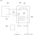
- FIG. 2 is schematic view of a micro-cogeneration system in accordance with an exemplary embodiment of the present invention.
- the cogeneration system in accordance with the present invention includes a co-generator 100 configured to recover waste heat using a heat transfer medium generated when electricity is generated, a boiler 200 configured to selectively circulate the heat transfer medium supplied from the co-generator 100 to any one of a place to be heated and a hot-water supply heat exchanger 230, and a heat transfer medium reservoir tank 300 configured to store the circulated heat transfer medium.
- the heat transfer medium refers to water, which is heating water.
- the co-generator 100 is an apparatus driven by, for example, a turbine (not shown) to generate electricity and simultaneously recover waste heat generated by the turbine.
- a heat exchanger 110 is installed at the co-generator 100 to recover the waste heat.
- the heat exchanger 110 is configured such that a heat transfer medium flows to recover the waste heat, and the heat transfer medium circulates the boiler 200.
- the boiler 200 includes a burner (not shown) configured to generate combustion heat, a main heat exchanger 210 configured to heat-exchange the combustion heat generated from the burner with the heat transfer medium supplied from the heat exchanger 110, a three-way valve 220 configured to selectively circulate the heat transfer medium supplied from the main heat exchanger 210 to any one of a place to be heated and the hot-water supply heat exchanger 230, a hot-water supply heat exchanger 230 configured to heat-exchange the heat transfer medium passing through the three-way valve 220 with tap water in a hot water mode, and a circulation pump 240 having an outlet side connected to the heat exchanger 110 of the co-generator 100 to circulate the heat transfer medium.
- a burner not shown
- main heat exchanger 210 configured to heat-exchange the combustion heat generated from the burner with the heat transfer medium supplied from the heat exchanger 110
- a three-way valve 220 configured to selectively circulate the heat transfer medium supplied from the main heat exchanger 210 to any one of a place to be heated and
- the tap water is introduced into the hot-water supply heat exchanger 230, and the tap water is heat-exchanged with the heat transfer medium passing through the three-way valve 220 to become hot water and then is supplied to a place at which the hot water is required.
- the heat transfer medium reservoir tank 300 is constituted by a sealed vessel to store the heat transfer medium and accumulate heat.
- the heat transfer medium having a temperature lowered after circulation of the place to be heated in the heating mode, i.e., returned water, is introduced into the heat transfer medium reservoir tank 300, and the heat transfer medium having a temperature lowered while passing through the hot-water supply heat exchanger 230 in the hot water mode is introduced into the heat transfer medium reservoir tank 300.
- the heat transfer medium introduced as described above is supplied into the heat exchanger 110 by driving the circulation pump 240, and for this, a pipe line through which the heat transfer medium flows is connected between the heat transfer medium reservoir tank 300 and the circulation pump 240.
- the system can be very simply configured.
- the heat transfer medium that absorbed the waste heat while passing though the heat exchanger 110 of the co-generator 100 may be supplied to the place to be heated and the hot-water supply heat exchanger 230 to use the waste heat for both of heating and hot water.
- the heat transfer medium channels (a heating channel and a hot water channel) of the co-generator and the boiler can be connected to each other while only the co-generator can be operated to accumulate heat energy when there is no hot water and heating load so that the accumulated heat energy can be used for both of heating and hot water, energy efficiency can be improved.
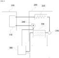
- FIG. 3 is a view showing a path through which the heat transfer medium circulates when there is no heating and hot water load in a cogeneration system of the present invention.
- circulation pump 240 in the boiler 200 is operated to circulate the heat transfer medium.
- the circulation pump 240 When the circulation pump 240 is operated, the heat transfer medium stored in the heat transfer medium reservoir tank 300 is introduced into the heat exchanger 110 of the co-generator 100 via the circulation pump 240.
- the co-generator 100 is operated to generate electricity and simultaneously waste heat, and heat energy is transmitted to the heat transfer medium passing through the heat exchanger 110 by the waste heat.
- the heat transfer medium passing through the heat exchanger 110 is supplied into the three-way valve 220 via the main heat exchanger 210.
- the heat transfer medium is supplied to the hot-water supply heat exchanger 230. In this case, since there is no hot water load, there is no heat exchange with tap water.
- the heat transfer medium passing through the hot-water supply heat exchanger 230 is introduced into the heat transfer medium reservoir tank 300.
- the heat transfer medium is circulated by repeating the above processes, and the closed circuit connected as described above forms a heat transfer medium channel.
- Detection of the temperature of the heat transfer medium is performed by a temperature detection means (not shown) installed at the heat transfer medium reservoir tank 300.
- FIG. 4 is a view showing a path through which the heat transfer medium circulates in the cogeneration system of the present invention in a heating mode.
- the boiler 200 When the heating mode is performed, the boiler 200 is operated to perform combustion in the burner (not shown), and the three-way valve 220 is set to block a flow of the heat transfer medium toward the hot-water supply heat exchanger 230 and allow a flow of the heat transfer medium toward the place to be heated.
- the boiler 200 may be configured to be operated only when a temperature of the heat transfer medium in the heat transfer medium reservoir tank 300 is measured and it is determined as a result of the measurement that the heat transfer medium in the heat transfer medium reservoir tank 300 is insufficient for a heating requirement.
- the circulation pump 240 When the circulation pump 240 is driven, the heat transfer medium stored in the heat transfer medium reservoir tank 300 is introduced into the heat exchanger 110 of the co-generator 100 via the circulation pump 240.
- the co-generator 100 may be shut down or may be operated to generate electricity to transmit heat energy to the heat transfer medium passing through the heat exchanger 110 using the waste heat generated therethrough.
- the heat transfer medium passing through the heat exchanger 110 is heated by the combustion heat of the burner (not shown) via the main heat exchanger 210, and then supplied into the three-way valve 220.
- the heat transfer medium which is heating supply water, passes through the place to be heated and is decreased in temperature, and then returns to be introduced into the heat transfer medium reservoir tank 300.
- FIG. 5 is a view showing a path through which the heat transfer medium circulates in the cogeneration system of the present invention in the hot water mode.
- the boiler 200 When the hot water mode is performed, the boiler 200 is operated to perform combustion in the burner (not shown), and the three-way valve 220 is set to block a flow of the heat transfer medium toward the place to be heated and allow a flow of the heat transfer medium toward the hot-water supply heat exchanger 230.
- the boiler 200 may be configured to be operated only when a temperature of the heat transfer medium in the heat transfer medium reservoir tank 300 is measured and it is determined as a result of the measurement that the heat transfer medium in the heat transfer medium reservoir tank 300 is insufficient for a hot water requirement.
- the flow of the heat transfer medium in the hot water mode is the same as the path of the heat transfer medium described with reference to FIG. 3 .
- the co-generator 100 may be shut down or may be operated to generate electricity to transfer heat energy to the heat transfer medium passing through the heat exchanger 110 by the waste heat generated therethrough.
- the main heat exchanger 210 heats the heat transfer medium using combustion heat of the burner (not shown), and then, supplies the heat transfer medium to the three-way valve 220.
- the hot-water supply heat exchanger 230 decreases the temperature of the heat transfer medium through heat exchange with tap water, and then introduces the heat transfer medium into the heat transfer medium reservoir tank 300.
- the processes are repeated to circulate the heat transfer medium, and the closed circuit connected as described above configures a hot water channel.
- a calorie control system of the boiler 200 can be used to precisely control the calories required to supply heating and hot water.
- the heat energy accumulated in the heat transfer medium reservoir tank 300 is used for heating or hot water, and only the co-generator 100 is operated when there is no heating and hot water load, reducing a cost consumed by the operation of the cogeneration system.
Landscapes
- Engineering & Computer Science (AREA)
- Physics & Mathematics (AREA)
- Thermal Sciences (AREA)
- Chemical & Material Sciences (AREA)
- Combustion & Propulsion (AREA)
- Mechanical Engineering (AREA)
- General Engineering & Computer Science (AREA)
- Water Supply & Treatment (AREA)
- Heat-Pump Type And Storage Water Heaters (AREA)
- Steam Or Hot-Water Central Heating Systems (AREA)
Claims (4)
- Procédé de fonctionnement pour un système de micro-cogénération, comprenant les étapes consistant à :faire fonctionner un co-générateur (100) incluant un échangeur de chaleur (110) pour récupérer la chaleur résiduelle générée lors de la génération de puissance ;stocker un médium de transfert de chaleur fourni par le co-générateur (100) dans une cuve de réservoir (300) de médium de transfert de chaleur via une chaudière (200) connectée à l'échangeur de chaleur (110) et contrôler le médium de transfert thermique stocké dans la cuve de réservoir (300) de médium de transfert de chaleur pour le faire circuler vers l'échangeur de chaleur (110) du co-générateur (100) pour absorber ladite chaleur résiduelle lorsqu'il passe dans ledit échangeur de chaleur (110), ledit médium de transfert de chaleur étant adapté pour être envoyé vers un endroit à chauffer et vers un échangeur thermique d'alimentation d'eau chaude (230) pour utiliser ladite chaleur résiduelle tant pour le chauffage que l'eau chaude ;faire fonctionner le co-générateur uniquement (100) lorsqu'il n'y a pas de chauffage ni de charge d'eau chaude ; etarrêter le fonctionnement du co-générateur (100) lorsqu'il est déterminé qu'une température du médium de transfert de chaleur dans la cuve de réservoir (300) de médium de transfert de chaleur arrive à une température prédéfinie.
- Procédé de fonctionnement pour un système de micro-cogénération selon la revendication 1, dans lequel, lorsqu'il n'y a pas de chauffage ni de charge d'eau chaude, un canal de circulation du médium de transfert de chaleur forme un canal de médium de transfert de chaleur en connectant séquentiellement la cuve de réservoir (300) de médium de transfert de chaleur, une pompe de circulation (240) installée dans la chaudière (200) pour faire circuler le médium de transfert de chaleur dans la cuve de réservoir (300) de médium de transfert de chaleur, l'échangeur de chaleur (110) du co-générateur (100) connecté à la pompe de circulation (240), un échangeur de chaleur principal (210) connecté à l'échangeur de chaleur (110) et installé dans la chaudière (200), une vanne trois voies (220) configurée pour alimenter de façon sélective le médium de transfert de chaleur amené depuis l'échangeur de chaleur principal (210) vers l'un quelconque des endroits à chauffer et l'échangeur thermique d'alimentation en eau chaude (230), et l'échangeur thermique d'alimentation en eau chaude (230) connecté à la vanne trois voies (220).
- Procédé de fonctionnement pour un système de micro-cogénération selon la revendication 1 dans lequel, lorsque le médium de transfert de chaleur alimenté depuis l'échangeur de chaleur principal (210) de la chaudière (200) est envoyé sélectivement vers l'un quelconque des endroits à chauffer et l'échangeur thermique d'alimentation en eau chaude (230), le médium de transfert de chaleur stocké dans la cuve de réservoir (300) de médium de transfert de chaleur est utilisé pour le chauffage et l'eau chaude.
- Procédé de fonctionnement pour un système de micro-cogénération selon l'une quelconque des revendications 1 à 3, dans lequel la chaudière est utilisée uniquement lorsque le médium de transfert thermique stocké dans la cuve de réservoir (300) de médium de transfert de chaleur est insuffisant pour un besoin de chauffage ou d'eau chaude.
Applications Claiming Priority (2)
| Application Number | Priority Date | Filing Date | Title |
|---|---|---|---|
| KR1020090093860A KR101199687B1 (ko) | 2009-10-01 | 2009-10-01 | 소형 열병합 발전 시스템의 운전방법 |
| PCT/KR2010/006090 WO2011040714A2 (fr) | 2009-10-01 | 2010-09-08 | Procédé de fonctionnement pour un système de micro-cogénération |
Publications (3)
| Publication Number | Publication Date |
|---|---|
| EP2484983A2 EP2484983A2 (fr) | 2012-08-08 |
| EP2484983A4 EP2484983A4 (fr) | 2016-06-08 |
| EP2484983B1 true EP2484983B1 (fr) | 2017-09-27 |
Family
ID=43826756
Family Applications (1)
| Application Number | Title | Priority Date | Filing Date |
|---|---|---|---|
| EP10820787.9A Not-in-force EP2484983B1 (fr) | 2009-10-01 | 2010-09-08 | Procédé de fonctionnement pour un système de micro-cogénération |
Country Status (4)
| Country | Link |
|---|---|
| EP (1) | EP2484983B1 (fr) |
| JP (1) | JP2013506810A (fr) |
| KR (1) | KR101199687B1 (fr) |
| WO (1) | WO2011040714A2 (fr) |
Families Citing this family (4)
| Publication number | Priority date | Publication date | Assignee | Title |
|---|---|---|---|---|
| KR101436842B1 (ko) * | 2012-12-26 | 2014-09-11 | 주식회사 경동나비엔 | 보일러의 난방배관 및 온수배관의 동파방지방법 |
| CN106679185A (zh) * | 2016-08-30 | 2017-05-17 | 神华集团有限责任公司 | 一种锅炉启动前的炉水加热方法及装置 |
| KR102443231B1 (ko) * | 2018-03-21 | 2022-09-15 | 아세아열기 주식회사 | 중앙난방과 가정용 보일러를 병행하는 냉난방장치 및 이의 제어방법 |
| US12455098B2 (en) | 2022-04-12 | 2025-10-28 | The Cleaver-Brooks Company, Inc. | Thermal efficiency system and method for boiler plant |
Family Cites Families (12)
| Publication number | Priority date | Publication date | Assignee | Title |
|---|---|---|---|---|
| DE19740398C2 (de) * | 1997-09-09 | 1999-12-02 | Vng Verbundnetz Gas Ag | Kraft-Wärme-gekoppelte Einrichtung zur Energieversorgung |
| KR100409134B1 (ko) * | 2001-10-11 | 2003-12-12 | (주)세티 | 연료전지 코제네레이션 시스템 |
| KR100418459B1 (ko) * | 2001-11-26 | 2004-02-14 | (주)세티 | 연료전지 시스템의 폐열을 보일러에 공급하기 위한 장치 |
| JP3834567B2 (ja) * | 2003-05-23 | 2006-10-18 | ネポン株式会社 | 施設園芸用温室における排熱回収兼用炭酸ガス供給システム |
| JP2005291561A (ja) * | 2004-03-31 | 2005-10-20 | Osaka Gas Co Ltd | コージェネレーションシステムの運転方法及びコージェネレーションシステム |
| AT413757B (de) * | 2004-09-13 | 2006-05-15 | Vaillant Gmbh | Verfahren zur gewährleistung eines hohen warmwasserkomforts bei mit brennstoffzellenheizgeräten beheizten warmwasserspeichern |
| KR100626993B1 (ko) * | 2005-01-20 | 2006-09-25 | 케이이설비연구소주식회사 | 도시가스 연료원 개별난방과 열병합발전 중앙난방을연계한 에너지 절약형 복합난방 시스템 |
| JP4421543B2 (ja) * | 2005-10-18 | 2010-02-24 | リンナイ株式会社 | コージェネレーションシステム |
| KR100713620B1 (ko) | 2006-05-26 | 2007-05-02 | 벽산건설 주식회사 | 열병합발전과 개별난방 통합시스템 |
| KR100740542B1 (ko) | 2006-05-30 | 2007-07-18 | 최성환 | 연료전지 폐열 회수 시스템 |
| JP4727680B2 (ja) * | 2008-02-25 | 2011-07-20 | 株式会社ノーリツ | 給湯装置 |
| JP2009204203A (ja) * | 2008-02-27 | 2009-09-10 | Noritz Corp | コージェネレーションシステム |
-
2009
- 2009-10-01 KR KR1020090093860A patent/KR101199687B1/ko active Active
-
2010
- 2010-09-08 WO PCT/KR2010/006090 patent/WO2011040714A2/fr not_active Ceased
- 2010-09-08 JP JP2012532000A patent/JP2013506810A/ja active Pending
- 2010-09-08 EP EP10820787.9A patent/EP2484983B1/fr not_active Not-in-force
Non-Patent Citations (1)
| Title |
|---|
| None * |
Also Published As
| Publication number | Publication date |
|---|---|
| WO2011040714A3 (fr) | 2011-07-21 |
| EP2484983A4 (fr) | 2016-06-08 |
| KR101199687B1 (ko) | 2012-11-08 |
| EP2484983A2 (fr) | 2012-08-08 |
| WO2011040714A2 (fr) | 2011-04-07 |
| KR20110036284A (ko) | 2011-04-07 |
| JP2013506810A (ja) | 2013-02-28 |
Similar Documents
| Publication | Publication Date | Title |
|---|---|---|
| EP2515050A1 (fr) | Système d'alimentation en eau chaude | |
| KR100740542B1 (ko) | 연료전지 폐열 회수 시스템 | |
| EP2484983B1 (fr) | Procédé de fonctionnement pour un système de micro-cogénération | |
| US20180205097A1 (en) | Fuel cell system | |
| JP5598083B2 (ja) | 廃熱回収システムおよびコージェネレーションシステム | |
| JP3563681B2 (ja) | 燃料電池コジェネシステム、および燃料電池コジェネシステムの運転方法 | |
| JP3933543B2 (ja) | 熱媒供給装置 | |
| KR20060122436A (ko) | 고효율 열병합 발전시스템 | |
| JP6088771B2 (ja) | 熱源装置 | |
| JP2013069598A (ja) | コージェネレーションシステム | |
| JP5317810B2 (ja) | 温水器 | |
| JP4850118B2 (ja) | 貯湯式給湯システムにおける給湯配管保温運転方法 | |
| CN103017234A (zh) | 太阳能锅炉供热系统 | |
| JP2012197987A (ja) | ヒートポンプ給湯機 | |
| JP4867273B2 (ja) | 給湯装置 | |
| JP6570908B2 (ja) | 給湯システム | |
| JP2016207581A (ja) | 燃料電池コージェネレーションシステム | |
| KR20110036285A (ko) | 소형 열병합 발전 시스템 | |
| KR20110036289A (ko) | 소형 열병합 발전 시스템 | |
| JP2006112648A (ja) | 給湯装置 | |
| JP4779571B2 (ja) | 給湯装置 | |
| JP6667161B2 (ja) | コージェネレーションシステム | |
| JP4867274B2 (ja) | 給湯装置 | |
| JP4715438B2 (ja) | 給湯装置 | |
| JP2017040379A (ja) | 熱源装置 |
Legal Events
| Date | Code | Title | Description |
|---|---|---|---|
| PUAI | Public reference made under article 153(3) epc to a published international application that has entered the european phase |
Free format text: ORIGINAL CODE: 0009012 |
|
| 17P | Request for examination filed |
Effective date: 20120428 |
|
| AK | Designated contracting states |
Kind code of ref document: A2 Designated state(s): AL AT BE BG CH CY CZ DE DK EE ES FI FR GB GR HR HU IE IS IT LI LT LU LV MC MK MT NL NO PL PT RO SE SI SK SM TR |
|
| DAX | Request for extension of the european patent (deleted) | ||
| A4 | Supplementary search report drawn up and despatched |
Effective date: 20160511 |
|
| RIC1 | Information provided on ipc code assigned before grant |
Ipc: F24D 19/10 20060101ALI20160504BHEP Ipc: F24D 10/00 20060101AFI20160504BHEP Ipc: F24D 12/02 20060101ALI20160504BHEP |
|
| RIC1 | Information provided on ipc code assigned before grant |
Ipc: F24D 12/02 20060101ALI20170313BHEP Ipc: F24D 19/10 20060101ALI20170313BHEP Ipc: F24D 10/00 20060101AFI20170313BHEP |
|
| GRAP | Despatch of communication of intention to grant a patent |
Free format text: ORIGINAL CODE: EPIDOSNIGR1 |
|
| INTG | Intention to grant announced |
Effective date: 20170424 |
|
| GRAS | Grant fee paid |
Free format text: ORIGINAL CODE: EPIDOSNIGR3 |
|
| GRAA | (expected) grant |
Free format text: ORIGINAL CODE: 0009210 |
|
| AK | Designated contracting states |
Kind code of ref document: B1 Designated state(s): AL AT BE BG CH CY CZ DE DK EE ES FI FR GB GR HR HU IE IS IT LI LT LU LV MC MK MT NL NO PL PT RO SE SI SK SM TR |
|
| REG | Reference to a national code |
Ref country code: GB Ref legal event code: FG4D |
|
| REG | Reference to a national code |
Ref country code: CH Ref legal event code: EP |
|
| REG | Reference to a national code |
Ref country code: AT Ref legal event code: REF Ref document number: 932317 Country of ref document: AT Kind code of ref document: T Effective date: 20171015 |
|
| REG | Reference to a national code |
Ref country code: IE Ref legal event code: FG4D |
|
| REG | Reference to a national code |
Ref country code: DE Ref legal event code: R096 Ref document number: 602010045616 Country of ref document: DE |
|
| REG | Reference to a national code |
Ref country code: NL Ref legal event code: FP |
|
| PG25 | Lapsed in a contracting state [announced via postgrant information from national office to epo] |
Ref country code: HR Free format text: LAPSE BECAUSE OF FAILURE TO SUBMIT A TRANSLATION OF THE DESCRIPTION OR TO PAY THE FEE WITHIN THE PRESCRIBED TIME-LIMIT Effective date: 20170927 Ref country code: FI Free format text: LAPSE BECAUSE OF FAILURE TO SUBMIT A TRANSLATION OF THE DESCRIPTION OR TO PAY THE FEE WITHIN THE PRESCRIBED TIME-LIMIT Effective date: 20170927 Ref country code: SE Free format text: LAPSE BECAUSE OF FAILURE TO SUBMIT A TRANSLATION OF THE DESCRIPTION OR TO PAY THE FEE WITHIN THE PRESCRIBED TIME-LIMIT Effective date: 20170927 Ref country code: NO Free format text: LAPSE BECAUSE OF FAILURE TO SUBMIT A TRANSLATION OF THE DESCRIPTION OR TO PAY THE FEE WITHIN THE PRESCRIBED TIME-LIMIT Effective date: 20171227 Ref country code: LT Free format text: LAPSE BECAUSE OF FAILURE TO SUBMIT A TRANSLATION OF THE DESCRIPTION OR TO PAY THE FEE WITHIN THE PRESCRIBED TIME-LIMIT Effective date: 20170927 |
|
| REG | Reference to a national code |
Ref country code: LT Ref legal event code: MG4D |
|
| REG | Reference to a national code |
Ref country code: AT Ref legal event code: MK05 Ref document number: 932317 Country of ref document: AT Kind code of ref document: T Effective date: 20170927 |
|
| PG25 | Lapsed in a contracting state [announced via postgrant information from national office to epo] |
Ref country code: LV Free format text: LAPSE BECAUSE OF FAILURE TO SUBMIT A TRANSLATION OF THE DESCRIPTION OR TO PAY THE FEE WITHIN THE PRESCRIBED TIME-LIMIT Effective date: 20170927 Ref country code: GR Free format text: LAPSE BECAUSE OF FAILURE TO SUBMIT A TRANSLATION OF THE DESCRIPTION OR TO PAY THE FEE WITHIN THE PRESCRIBED TIME-LIMIT Effective date: 20171228 Ref country code: BG Free format text: LAPSE BECAUSE OF FAILURE TO SUBMIT A TRANSLATION OF THE DESCRIPTION OR TO PAY THE FEE WITHIN THE PRESCRIBED TIME-LIMIT Effective date: 20171227 |
|
| PG25 | Lapsed in a contracting state [announced via postgrant information from national office to epo] |
Ref country code: ES Free format text: LAPSE BECAUSE OF FAILURE TO SUBMIT A TRANSLATION OF THE DESCRIPTION OR TO PAY THE FEE WITHIN THE PRESCRIBED TIME-LIMIT Effective date: 20170927 Ref country code: RO Free format text: LAPSE BECAUSE OF FAILURE TO SUBMIT A TRANSLATION OF THE DESCRIPTION OR TO PAY THE FEE WITHIN THE PRESCRIBED TIME-LIMIT Effective date: 20170927 Ref country code: CZ Free format text: LAPSE BECAUSE OF FAILURE TO SUBMIT A TRANSLATION OF THE DESCRIPTION OR TO PAY THE FEE WITHIN THE PRESCRIBED TIME-LIMIT Effective date: 20170927 |
|
| PG25 | Lapsed in a contracting state [announced via postgrant information from national office to epo] |
Ref country code: EE Free format text: LAPSE BECAUSE OF FAILURE TO SUBMIT A TRANSLATION OF THE DESCRIPTION OR TO PAY THE FEE WITHIN THE PRESCRIBED TIME-LIMIT Effective date: 20170927 Ref country code: SM Free format text: LAPSE BECAUSE OF FAILURE TO SUBMIT A TRANSLATION OF THE DESCRIPTION OR TO PAY THE FEE WITHIN THE PRESCRIBED TIME-LIMIT Effective date: 20170927 Ref country code: AT Free format text: LAPSE BECAUSE OF FAILURE TO SUBMIT A TRANSLATION OF THE DESCRIPTION OR TO PAY THE FEE WITHIN THE PRESCRIBED TIME-LIMIT Effective date: 20170927 Ref country code: IS Free format text: LAPSE BECAUSE OF FAILURE TO SUBMIT A TRANSLATION OF THE DESCRIPTION OR TO PAY THE FEE WITHIN THE PRESCRIBED TIME-LIMIT Effective date: 20180127 Ref country code: IT Free format text: LAPSE BECAUSE OF FAILURE TO SUBMIT A TRANSLATION OF THE DESCRIPTION OR TO PAY THE FEE WITHIN THE PRESCRIBED TIME-LIMIT Effective date: 20170927 Ref country code: SK Free format text: LAPSE BECAUSE OF FAILURE TO SUBMIT A TRANSLATION OF THE DESCRIPTION OR TO PAY THE FEE WITHIN THE PRESCRIBED TIME-LIMIT Effective date: 20170927 |
|
| REG | Reference to a national code |
Ref country code: DE Ref legal event code: R097 Ref document number: 602010045616 Country of ref document: DE |
|
| PG25 | Lapsed in a contracting state [announced via postgrant information from national office to epo] |
Ref country code: DK Free format text: LAPSE BECAUSE OF FAILURE TO SUBMIT A TRANSLATION OF THE DESCRIPTION OR TO PAY THE FEE WITHIN THE PRESCRIBED TIME-LIMIT Effective date: 20170927 |
|
| PLBE | No opposition filed within time limit |
Free format text: ORIGINAL CODE: 0009261 |
|
| STAA | Information on the status of an ep patent application or granted ep patent |
Free format text: STATUS: NO OPPOSITION FILED WITHIN TIME LIMIT |
|
| PG25 | Lapsed in a contracting state [announced via postgrant information from national office to epo] |
Ref country code: PL Free format text: LAPSE BECAUSE OF FAILURE TO SUBMIT A TRANSLATION OF THE DESCRIPTION OR TO PAY THE FEE WITHIN THE PRESCRIBED TIME-LIMIT Effective date: 20170927 |
|
| 26N | No opposition filed |
Effective date: 20180628 |
|
| PGFP | Annual fee paid to national office [announced via postgrant information from national office to epo] |
Ref country code: DE Payment date: 20180828 Year of fee payment: 9 |
|
| PG25 | Lapsed in a contracting state [announced via postgrant information from national office to epo] |
Ref country code: SI Free format text: LAPSE BECAUSE OF FAILURE TO SUBMIT A TRANSLATION OF THE DESCRIPTION OR TO PAY THE FEE WITHIN THE PRESCRIBED TIME-LIMIT Effective date: 20170927 |
|
| PGFP | Annual fee paid to national office [announced via postgrant information from national office to epo] |
Ref country code: NL Payment date: 20180912 Year of fee payment: 9 Ref country code: GB Payment date: 20180905 Year of fee payment: 9 |
|
| PG25 | Lapsed in a contracting state [announced via postgrant information from national office to epo] |
Ref country code: MC Free format text: LAPSE BECAUSE OF FAILURE TO SUBMIT A TRANSLATION OF THE DESCRIPTION OR TO PAY THE FEE WITHIN THE PRESCRIBED TIME-LIMIT Effective date: 20170927 |
|
| REG | Reference to a national code |
Ref country code: CH Ref legal event code: PL |
|
| REG | Reference to a national code |
Ref country code: BE Ref legal event code: MM Effective date: 20180930 |
|
| REG | Reference to a national code |
Ref country code: IE Ref legal event code: MM4A |
|
| PG25 | Lapsed in a contracting state [announced via postgrant information from national office to epo] |
Ref country code: LU Free format text: LAPSE BECAUSE OF NON-PAYMENT OF DUE FEES Effective date: 20180908 |
|
| PG25 | Lapsed in a contracting state [announced via postgrant information from national office to epo] |
Ref country code: IE Free format text: LAPSE BECAUSE OF NON-PAYMENT OF DUE FEES Effective date: 20180908 |
|
| PG25 | Lapsed in a contracting state [announced via postgrant information from national office to epo] |
Ref country code: BE Free format text: LAPSE BECAUSE OF NON-PAYMENT OF DUE FEES Effective date: 20180930 Ref country code: FR Free format text: LAPSE BECAUSE OF NON-PAYMENT OF DUE FEES Effective date: 20180930 Ref country code: CH Free format text: LAPSE BECAUSE OF NON-PAYMENT OF DUE FEES Effective date: 20180930 Ref country code: LI Free format text: LAPSE BECAUSE OF NON-PAYMENT OF DUE FEES Effective date: 20180930 |
|
| PG25 | Lapsed in a contracting state [announced via postgrant information from national office to epo] |
Ref country code: MT Free format text: LAPSE BECAUSE OF NON-PAYMENT OF DUE FEES Effective date: 20180908 |
|
| PG25 | Lapsed in a contracting state [announced via postgrant information from national office to epo] |
Ref country code: TR Free format text: LAPSE BECAUSE OF FAILURE TO SUBMIT A TRANSLATION OF THE DESCRIPTION OR TO PAY THE FEE WITHIN THE PRESCRIBED TIME-LIMIT Effective date: 20170927 |
|
| REG | Reference to a national code |
Ref country code: DE Ref legal event code: R119 Ref document number: 602010045616 Country of ref document: DE |
|
| REG | Reference to a national code |
Ref country code: NL Ref legal event code: MM Effective date: 20191001 |
|
| PG25 | Lapsed in a contracting state [announced via postgrant information from national office to epo] |
Ref country code: HU Free format text: LAPSE BECAUSE OF FAILURE TO SUBMIT A TRANSLATION OF THE DESCRIPTION OR TO PAY THE FEE WITHIN THE PRESCRIBED TIME-LIMIT; INVALID AB INITIO Effective date: 20100908 Ref country code: PT Free format text: LAPSE BECAUSE OF FAILURE TO SUBMIT A TRANSLATION OF THE DESCRIPTION OR TO PAY THE FEE WITHIN THE PRESCRIBED TIME-LIMIT Effective date: 20170927 |
|
| PG25 | Lapsed in a contracting state [announced via postgrant information from national office to epo] |
Ref country code: CY Free format text: LAPSE BECAUSE OF FAILURE TO SUBMIT A TRANSLATION OF THE DESCRIPTION OR TO PAY THE FEE WITHIN THE PRESCRIBED TIME-LIMIT Effective date: 20170927 Ref country code: MK Free format text: LAPSE BECAUSE OF NON-PAYMENT OF DUE FEES Effective date: 20170927 |
|
| PG25 | Lapsed in a contracting state [announced via postgrant information from national office to epo] |
Ref country code: NL Free format text: LAPSE BECAUSE OF NON-PAYMENT OF DUE FEES Effective date: 20191001 Ref country code: DE Free format text: LAPSE BECAUSE OF NON-PAYMENT OF DUE FEES Effective date: 20200401 Ref country code: AL Free format text: LAPSE BECAUSE OF FAILURE TO SUBMIT A TRANSLATION OF THE DESCRIPTION OR TO PAY THE FEE WITHIN THE PRESCRIBED TIME-LIMIT Effective date: 20170927 |
|
| GBPC | Gb: european patent ceased through non-payment of renewal fee |
Effective date: 20190908 |
|
| PG25 | Lapsed in a contracting state [announced via postgrant information from national office to epo] |
Ref country code: GB Free format text: LAPSE BECAUSE OF NON-PAYMENT OF DUE FEES Effective date: 20190908 |