EP2485109A2 - Système de carburant de mesure directe avec débit de servo constant - Google Patents
Système de carburant de mesure directe avec débit de servo constant Download PDFInfo
- Publication number
- EP2485109A2 EP2485109A2 EP20120153951 EP12153951A EP2485109A2 EP 2485109 A2 EP2485109 A2 EP 2485109A2 EP 20120153951 EP20120153951 EP 20120153951 EP 12153951 A EP12153951 A EP 12153951A EP 2485109 A2 EP2485109 A2 EP 2485109A2
- Authority
- EP
- European Patent Office
- Prior art keywords
- fuel
- flow
- regulator
- pump
- outlet port
- Prior art date
- Legal status (The legal status is an assumption and is not a legal conclusion. Google has not performed a legal analysis and makes no representation as to the accuracy of the status listed.)
- Granted
Links
- 239000000446 fuel Substances 0.000 title claims abstract description 260
- 239000012530 fluid Substances 0.000 claims abstract description 43
- 238000006073 displacement reaction Methods 0.000 claims description 17
- 238000000034 method Methods 0.000 description 5
- 230000001276 controlling effect Effects 0.000 description 3
- 238000010586 diagram Methods 0.000 description 2
- 239000002828 fuel tank Substances 0.000 description 2
- 230000033228 biological regulation Effects 0.000 description 1
- 230000007423 decrease Effects 0.000 description 1
- 230000001419 dependent effect Effects 0.000 description 1
- 238000007599 discharging Methods 0.000 description 1
- 230000001105 regulatory effect Effects 0.000 description 1
- 238000004513 sizing Methods 0.000 description 1
- 238000011144 upstream manufacturing Methods 0.000 description 1
Images


Classifications
-
- F—MECHANICAL ENGINEERING; LIGHTING; HEATING; WEAPONS; BLASTING
- F02—COMBUSTION ENGINES; HOT-GAS OR COMBUSTION-PRODUCT ENGINE PLANTS
- F02D—CONTROLLING COMBUSTION ENGINES
- F02D41/00—Electrical control of supply of combustible mixture or its constituents
- F02D41/30—Controlling fuel injection
- F02D41/38—Controlling fuel injection of the high pressure type
- F02D41/40—Controlling fuel injection of the high pressure type with means for controlling injection timing or duration
- F02D41/406—Electrically controlling a diesel injection pump
-
- F—MECHANICAL ENGINEERING; LIGHTING; HEATING; WEAPONS; BLASTING
- F04—POSITIVE - DISPLACEMENT MACHINES FOR LIQUIDS; PUMPS FOR LIQUIDS OR ELASTIC FLUIDS
- F04B—POSITIVE-DISPLACEMENT MACHINES FOR LIQUIDS; PUMPS
- F04B49/00—Control, e.g. of pump delivery, or pump pressure of, or safety measures for, machines, pumps, or pumping installations, not otherwise provided for, or of interest apart from, groups F04B1/00 - F04B47/00
- F04B49/06—Control using electricity
- F04B49/065—Control using electricity and making use of computers
-
- F—MECHANICAL ENGINEERING; LIGHTING; HEATING; WEAPONS; BLASTING
- F04—POSITIVE - DISPLACEMENT MACHINES FOR LIQUIDS; PUMPS FOR LIQUIDS OR ELASTIC FLUIDS
- F04B—POSITIVE-DISPLACEMENT MACHINES FOR LIQUIDS; PUMPS
- F04B49/00—Control, e.g. of pump delivery, or pump pressure of, or safety measures for, machines, pumps, or pumping installations, not otherwise provided for, or of interest apart from, groups F04B1/00 - F04B47/00
- F04B49/22—Control, e.g. of pump delivery, or pump pressure of, or safety measures for, machines, pumps, or pumping installations, not otherwise provided for, or of interest apart from, groups F04B1/00 - F04B47/00 by means of valves
- F04B49/24—Bypassing
-
- F—MECHANICAL ENGINEERING; LIGHTING; HEATING; WEAPONS; BLASTING
- F04—POSITIVE - DISPLACEMENT MACHINES FOR LIQUIDS; PUMPS FOR LIQUIDS OR ELASTIC FLUIDS
- F04B—POSITIVE-DISPLACEMENT MACHINES FOR LIQUIDS; PUMPS
- F04B2205/00—Fluid parameters
- F04B2205/09—Flow through the pump
-
- Y—GENERAL TAGGING OF NEW TECHNOLOGICAL DEVELOPMENTS; GENERAL TAGGING OF CROSS-SECTIONAL TECHNOLOGIES SPANNING OVER SEVERAL SECTIONS OF THE IPC; TECHNICAL SUBJECTS COVERED BY FORMER USPC CROSS-REFERENCE ART COLLECTIONS [XRACs] AND DIGESTS
- Y02—TECHNOLOGIES OR APPLICATIONS FOR MITIGATION OR ADAPTATION AGAINST CLIMATE CHANGE
- Y02T—CLIMATE CHANGE MITIGATION TECHNOLOGIES RELATED TO TRANSPORTATION
- Y02T10/00—Road transport of goods or passengers
- Y02T10/10—Internal combustion engine [ICE] based vehicles
- Y02T10/40—Engine management systems
-
- Y—GENERAL TAGGING OF NEW TECHNOLOGICAL DEVELOPMENTS; GENERAL TAGGING OF CROSS-SECTIONAL TECHNOLOGIES SPANNING OVER SEVERAL SECTIONS OF THE IPC; TECHNICAL SUBJECTS COVERED BY FORMER USPC CROSS-REFERENCE ART COLLECTIONS [XRACs] AND DIGESTS
- Y10—TECHNICAL SUBJECTS COVERED BY FORMER USPC
- Y10T—TECHNICAL SUBJECTS COVERED BY FORMER US CLASSIFICATION
- Y10T137/00—Fluid handling
- Y10T137/0318—Processes
-
- Y—GENERAL TAGGING OF NEW TECHNOLOGICAL DEVELOPMENTS; GENERAL TAGGING OF CROSS-SECTIONAL TECHNOLOGIES SPANNING OVER SEVERAL SECTIONS OF THE IPC; TECHNICAL SUBJECTS COVERED BY FORMER USPC CROSS-REFERENCE ART COLLECTIONS [XRACs] AND DIGESTS
- Y10—TECHNICAL SUBJECTS COVERED BY FORMER USPC
- Y10T—TECHNICAL SUBJECTS COVERED BY FORMER US CLASSIFICATION
- Y10T137/00—Fluid handling
- Y10T137/2496—Self-proportioning or correlating systems
- Y10T137/2559—Self-controlled branched flow systems
- Y10T137/2574—Bypass or relief controlled by main line fluid condition
- Y10T137/2579—Flow rate responsive
- Y10T137/2587—Bypass or relief valve biased open
-
- Y—GENERAL TAGGING OF NEW TECHNOLOGICAL DEVELOPMENTS; GENERAL TAGGING OF CROSS-SECTIONAL TECHNOLOGIES SPANNING OVER SEVERAL SECTIONS OF THE IPC; TECHNICAL SUBJECTS COVERED BY FORMER USPC CROSS-REFERENCE ART COLLECTIONS [XRACs] AND DIGESTS
- Y10—TECHNICAL SUBJECTS COVERED BY FORMER USPC
- Y10T—TECHNICAL SUBJECTS COVERED BY FORMER US CLASSIFICATION
- Y10T137/00—Fluid handling
- Y10T137/2496—Self-proportioning or correlating systems
- Y10T137/2559—Self-controlled branched flow systems
- Y10T137/2574—Bypass or relief controlled by main line fluid condition
- Y10T137/2579—Flow rate responsive
- Y10T137/2592—Carried choke
-
- Y—GENERAL TAGGING OF NEW TECHNOLOGICAL DEVELOPMENTS; GENERAL TAGGING OF CROSS-SECTIONAL TECHNOLOGIES SPANNING OVER SEVERAL SECTIONS OF THE IPC; TECHNICAL SUBJECTS COVERED BY FORMER USPC CROSS-REFERENCE ART COLLECTIONS [XRACs] AND DIGESTS
- Y10—TECHNICAL SUBJECTS COVERED BY FORMER USPC
- Y10T—TECHNICAL SUBJECTS COVERED BY FORMER US CLASSIFICATION
- Y10T137/00—Fluid handling
- Y10T137/2496—Self-proportioning or correlating systems
- Y10T137/2559—Self-controlled branched flow systems
- Y10T137/265—Plural outflows
- Y10T137/2657—Flow rate responsive
-
- Y—GENERAL TAGGING OF NEW TECHNOLOGICAL DEVELOPMENTS; GENERAL TAGGING OF CROSS-SECTIONAL TECHNOLOGIES SPANNING OVER SEVERAL SECTIONS OF THE IPC; TECHNICAL SUBJECTS COVERED BY FORMER USPC CROSS-REFERENCE ART COLLECTIONS [XRACs] AND DIGESTS
- Y10—TECHNICAL SUBJECTS COVERED BY FORMER USPC
- Y10T—TECHNICAL SUBJECTS COVERED BY FORMER US CLASSIFICATION
- Y10T137/00—Fluid handling
- Y10T137/7722—Line condition change responsive valves
- Y10T137/7781—With separate connected fluid reactor surface
- Y10T137/7793—With opening bias [e.g., pressure regulator]
- Y10T137/7797—Bias variable during operation
- Y10T137/7798—Ancillary reactor surface responds to inlet pressure
Definitions
- This disclosure generally relates to fuel metering systems and, more particularly, to a direct metering fuel system with a constant servo flow draw.
- Many gas turbine engine fuel supply systems include a fuel source, such as a fuel tank, and one or more pumps that draw fuel from the fuel source and deliver pressurized fuel to the fuel manifolds in the engine combustor via a main supply line.
- the main supply line may include one or more valves in flow series between the pumps and the fuel manifolds. These valves generally include, for example, a main metering valve and a pressurizing-and-shutoff valve downstream of the main metering valve.
- many fuel supply systems also include a bypass flow line connected upstream of the metering valve that bypasses a portion of the fuel flowing in the main supply line back to the inlet of the one or more pumps, via a bypass valve. The position of the bypass valve is typically controlled by a head regulation scheme to maintain a substantially fixed differential pressure across the main metering valve.
- the above-described fuel supply system is generally safe, reliable, and robust. Nonetheless, it can suffer certain drawbacks.
- the metering valve and bypass valve can add to overall system weight and complexity.
- control of the metering valve and bypass valve can result in increased system complexity and cost.
- fuel flow rate is controlled by controlling a fuel metering pump.
- the speed or the displacement of the fuel metering pump may be controlled.
- efforts to implement direct fuel metering control systems have also been impeded by certain drawbacks.
- many gas turbine engines include one or more fluid-operated actuators. In many instances these actuators are driven by the fuel from the fuel supply system. Thus, actuator operation can cause a droop in the fuel supplied to the engine, and thus an undesirable engine speed droop. It is also postulated that such fuel supply variations to the engine could yield unpredictable, and potentially less controllable, engine transients.
- a direct metering fuel supply system includes a fuel pump, a burn flow fuel line, a servo flow fuel line, and a servo regulator.
- the fuel pump includes a pump inlet and a pump outlet.
- the fuel pump is adapted receive pump commands representative of a commanded fuel flow rate and is configured, in response to the pump commands, to draw fuel into the pump inlet and discharge fuel out the pump outlet at the commanded fuel flow rate.
- the burn flow fuel line is in fluid communication with the pump outlet to receive a first portion of the fuel discharged therefrom.
- the servo flow fuel line is in fluid communication with the pump outlet to receive a second portion of the fuel discharged therefrom.
- the servo regulator is mounted on the servo flow fuel line and configured to maintain fuel flow rate in the servo flow fuel line at a substantially constant fuel flow rate regardless of fuel flow rate in the burn flow fuel line.
- a direct metering fuel supply system in another embodiment, includes a fuel pump, a burn flow fuel line, a servo flow fuel line, and a servo regulator.
- the fuel pump has a pump inlet and a pump outlet.
- the fuel pump is configured to be driven at a rotational speed and is operable, upon being driven, to draw fuel into the pump inlet and discharge fuel out the pump outlet at a fuel flow rate that is dependent on the rotational speed.
- the burn flow fuel line is in fluid communication with the pump outlet to receive a first portion of the fuel discharged therefrom.
- the servo flow fuel line is in fluid communication with the pump outlet to receive a second portion of the fuel discharged therefrom.
- the servo regulator is mounted on the servo flow fuel line and is configured to maintain fuel flow rate in the servo flow fuel line at a substantially constant fuel flow rate regardless of fuel flow rate in the burn flow fuel line.
- a method of controlling fuel flow in a direct metered fuel supply system includes discharging fuel from a fuel pump at a commanded fuel flow rate. A first portion of the fuel discharged from the fuel pump is directed into a burn flow fuel line, and a second portion of the fuel discharged from the fuel pump is directed into a servo flow fuel line. Fuel flow rate in the servo flow fuel line is maintained at a substantially constant fuel flow rate regardless of fuel flow rate in the burn flow fuel line.
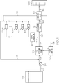
- FIG. 1 is a simplified schematic diagram of an exemplary embodiment of a fuel delivery and control system for a gas turbine engine
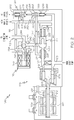
- FIG. 2 is a schematic representation of an exemplary embodiment of a portion of a fuel supply system that may be used to implement the system of FIG. 1 ;
- FIGS. 3 and 4 depict schematic representations of the servo flow regulator valve depicted in FIG. 2 in a first position and a second position, respectively.
- FIG. 1 A simplified schematic diagram of one embodiment of a direct metering fuel control system 100 for a gas turbine engine, such as a turbofan jet aircraft engine, is depicted in FIG. 1 .
- the system 100 includes a fuel source 102, one or more pumps 104, 106, and an engine control 150.
- the fuel source 102 which is preferably implemented as one or more tanks, stores fuel that is to be supplied to a plurality of fuel loads 108 (e.g. 108-1, 108-2, 108-3, ... 108-N). It will be appreciated that the number and type of fuel loads may vary, and may include a gas turbine engine combustor zone and associated nozzles 108-1, and a plurality of other remote devices 108-2, 108-3, 108-4, ...
- the number and type of remote devices may vary. In the depicted embodiment, however, these include a motive flow valve and regulator 108-2, one or more variable geometry actuators 108-3, and one or more bleed valves 108-4, just to name a few.
- the fuel loads 108 may, in some instances, be referred to as primary (or burn flow) fuel loads and secondary (or servo flow) fuel loads based, for example, on functionality. Though the classifications may vary, the gas turbine engine combustor zone and associated nozzles 108-1 are typically classified as primary (or burn flow) fuel loads, and the remote devices 108-2, 108-3, 108-4, ... 108-N, such as the motive flow valve and regulator 108-2, the one or more variable geometry actuators 108-3, and the one or more bleed valves 108-4, are typically classified as secondary (or servo flow) fuel loads.
- the one or more pumps 104, 106 are positioned in flow-series in a supply line 112 and take a suction on the fuel source 102.
- a boost pump 104 such as a relatively low horsepower centrifugal pump, and a high-pressure fuel metering pump 106 are used.
- the boost pump 104 draws fuel directly from the fuel source 102 and provides sufficient suction head for the fuel metering pump 106.
- the boost pump 104 may be either mechanically driven by the engine, or electrically driven by a non-illustrated motor.
- the system 100 may additionally include a low pressure pump within the fuel tank(s) 102 to supply fuel to the boost pump 104.
- the boost pump 104 may, in some embodiments, not be included.
- the fuel metering pump 106 includes a pump inlet 105 and a pump outlet 107, and is coupled to receive pump commands representative of a commanded fuel flow rate from the engine control 150.
- the fuel metering pump 106 is configured, in response to the pump commands, to draw fuel into the pump inlet 105 and discharge fuel, at the commanded fuel flow rate and at a relatively high pump discharge pressure, out the pump outlet 107.
- the fuel metering pump 106 may be variously configured and implemented.
- the fuel metering pump 106 may be a positive displacement piston, gear, or vane pump.
- the positive displacement pump may be either a variable displacement pump or a fixed displacement pump.
- the fuel metering pump 106 is implemented as an electric motor driven fixed displacement pump.
- the engine control 150 which may be implemented within an engine controller, such as a Full Authority Digital Engine Controller (FADEC) or other electronic engine controller (EEC), controls the flow rate of fuel to the fuel loads 108. To do so, the engine control 150 receives various input signals and controls the operation of the fuel metering pump 106, and thus the fuel flow rate, accordingly. In the depicted embodiment, the engine control 150 receives an engine speed command signal 152, which is representative of a desired engine speed, from non-illustrated throttle control equipment in, for example, a non-illustrated cockpit. The engine control 150 is configured, in response to the engine speed command signal 152, to determine the fuel flow rate needed by the fuel loads 108.
- FADEC Full Authority Digital Engine Controller
- EEC electronic engine controller
- the engine control 150 based on this determination, supplies the pump commands to the fuel metering pump 106 to supply the combined fuel flow rate needed by fuel loads 108.
- the engine control 150 is configured as a multichannel device, in which one channel is operable and the remaining channels are in a standby mode. Although the number of channels may vary, in a particular preferred embodiment, the engine control 150 includes two independent channels.
- the supply line 112 is coupled to the fuel source 102 and, via the one or more pumps 104, 106, delivers the fuel to the fuel loads 108. It is noted that the supply line 112 is, for convenience, depicted and described as including a burn flow fuel line 112-1 and a servo flow fuel line 112-2.
- the burn flow fuel line 112-1 is in fluid communication with, and receives a first portion of the fuel discharged from, the pump outlet 107, and delivers the first portion of the fuel to the primary (or burn flow) fuel loads (e.g., 108-1).
- the servo flow fuel line 112-2 is in fluid communication with, and receives a second portion of the fuel discharged from, the pump outlet 107, and delivers at least part of the second portion of fuel to the secondary (or servo flow) fuel loads (e.g., 108-2, 108-3, 108-4 ... 108-N).
- the system 100 includes a servo flow return line 113.
- the servo flow return line 113 is in fluid communication with the remote devices 108-2, 108-3, 108-4 ... 108-N and the pump inlet 105, and returns an equivalent amount of fuel that is supplied to the remote devices 108-2, 108-3, 108-4 ... 108-N back to the pump inlet 105.
- the depicted direct metering fuel control system 100 additionally includes a pressurizing valve 114, a shut-off valve 116, and a servo regulator 120.
- the pressurizing valve 114 and the shut-off valve 116 are mounted on the burn flow line 112-1.
- the pressurizing valve 114 functions to ensure there is a minimum system pressure magnitude in the burn flow line 112-1.
- the shut-off valve 116 which is preferably an electrically actuated valve, is commanded by the engine control 150.
- the shut-off valve 116 in response to commands supplied from the engine control 150, either allows fuel to flow to the engine via the burn flow fuel line 112-1, or directs fuel flow back to the pump inlet 105 via the burn flow return line 118 and the servo return line 113.
- the servo regulator 120 is mounted on the servo flow line 112-2 and is configured to maintain fuel flow rate in the servo flow fuel line 112-2 at a substantially constant fuel flow rate, regardless of the fuel flow rate in the burn flow fuel line 112-1.
- the servo regulator 120 may be variously configured to implement this functionality, one particular implementation is illustrated in FIG. 2 , and with reference thereto it, and other system components, will be described.
- the fuel metering pump 106 includes a pump 202 and a motor 204.
- the pump 202 is coupled to the motor 204 and, in response to a drive torque supplied thereto from the motor 204, draws fuel into the pump inlet 105 and discharges fuel, at the commanded fuel flow rate and at a relatively high pump discharge pressure, out the pump outlet 107.
- the depicted pump 202 is a fixed displacement, variable speed positive displacement piston pump, and includes a pump rotor (or shaft) 206 that is coupled to the motor 204.
- a fixed displacement, variable speed positive displacement piston pump exhibits generally linear flow versus drive speed characteristics.
- the flow rate at which the pump 202 supplies fuel is controlled based on the drive speed of the motor 204 that is supplying the drive torque.
- the depicted motor 204 is implemented as brushless DC motor that includes a stator 208 and a permanent magnet rotor 212.
- the stator 208 surrounds the permanent magnet rotor 212, which is rotationally mounted via a bearing assembly 213 and is coupled to the pump shaft 206.
- the permanent magnet rotor 212 and pump shaft 206 thus share the bearing assembly 213.
- the stator 208 associated may be selectively energized, using known brushless DC motor commutation techniques, to generate a rotating magnetic field.
- the rotor 212 will in turn rotate, and supply a drive torque to the pump 202.
- the engine control 150 is coupled to the stator 208 and implements, among other functions, appropriate brushless DC motor commutation. It will be appreciated that the motor 204 and the engine control 150 may be configured to implement either sensorless or position feedback motor commutation techniques. No matter the particular commutation technique that is employed, the speed of the motor 204, and the concomitant drive torque supplied by the motor 204 to the pump 202, is controlled such that the pump 202 supplies fuel at the fuel flow rate determined by the engine control 150. It will be appreciated that the motor 204 may be implemented using any one of numerous types of AC or DC motors, and that a brushless DC motor is merely exemplary of one particular embodiment.
- the fuel that is discharged from the pump outlet 107 flows into the burn flow fuel line 112-1 and, via a wash filter 214, into the servo flow fuel line 112-2.
- a pump relief valve 216 may be disposed between the pump outlet 107 and the pump inlet 105.
- the pump relief valve 216 if included, is normally closed, which is the position depicted in FIG. 2 . However, if a preset fluid pressure is reached at the pump outlet 107, the pump relief valve 216 will open, and relieve the pressure by fluidly communicating the pump outlet 107 to the pump inlet 105.
- the fuel in the burn flow fuel line 112-1 will also flow through the pressurizing valve 114, when fuel pressure in the burn flow line 112-1 attains a predetermined minimum fluid pressure.
- the fuel then flows through the shut-off valve 116, when the shut-off valve 116 is in the position depicted in FIG. 2 , and then through burn flow fuel line 112-1 to the gas turbine engine combustor zone and associated nozzles 108-1 (non depicted in FIG. 2 ).
- the pressurizing valve 114 and the shut-off valve 116 may be variously configured and implemented. For completeness, however, descriptions of the depicted implementations will now be provided.
- the pressurizing valve 114 includes a valve body 222, a valve element 224, and a spring 226.
- the valve body 222 includes an inlet port 228, an outlet port 232, and a sense port 234.
- the inlet port 228 is in fluid communication with the pump outlet 107, and the sense port 234 is in fluid communication with the pump inlet 105.
- the valve element 224 and the spring 226 are disposed within the valve body 222.
- the valve element 224 is configured to move between a closed position, in which the inlet port 228 is fluidly isolated from the outlet port 232, and an open position (which is depicted in FIG. 2 ), in which the inlet port 228 is in fluid communication with the outlet port 232.
- the spring 226 is configured to supply a bias force to the valve element 224 that, together with the fluid pressure at the sense port 234, urges the valve element 224 toward the closed position.
- the pressurizing valve 114 will remain in the closed position until fluid pressure at the inlet port 228 attains a predetermined minimum opening fluid pressure, at which point it will move to an open flowing position.
- the position of pressurizing valve element 224 varies the area of discharge outlet port 232, maintaining the fuel pressure in burn flow line 112-1 to the predetermined minimum pressure above pump inlet 105.
- the pressurizing valve 114 remains open until the fluid pressure at the inlet port 228 falls below a predetermined closing fluid pressure.
- the shut-off valve 116 is mounted on the burn flow fuel line 112-1 downstream of the pressurizing valve 114, and includes a valve body 236 and a valve element 238.
- the valve body 236 includes an inlet port 242, a burn flow outlet port 244, and a bypass outlet port 246.
- the inlet port 242 in fluid communication with the pressurizing valve outlet port 232, and the bypass outlet port 246 is in fluid communication with the pump inlet 105.
- the valve element 238 is disposed within the valve body 236 and is coupled to a valve actuator 248.
- the valve actuator 248 is implemented using a spring-loaded solenoid. It will be appreciated, however, that the valve actuator 248 could be implemented using any one of numerous suitable actuation devices.
- valve actuator 248 it is used to move the valve element 238 between a first position and a second position.
- first position which is the position depicted in FIG. 2
- the inlet port 242 is in fluid communication with the burn flow outlet port 244 and is fluidly isolated from the bypass outlet port 246.
- second position the inlet port 242 is fluidly isolated from the burn flow outlet port 244 and is in fluid communication with the bypass outlet port 246.
- the depicted servo regulator 120 includes a servo pressure regulator 252 and a servo flow regulator 254.
- the depicted servo pressure regulator 252 includes a pressure regulator valve body 256 and a pressure regulator valve element 258.
- the pressure regulator valve body 256 includes a pressure regulator inlet port 262, a pressure regulator outlet port 264, and a return pressure sense port 266.
- the pressure regulator inlet port 262 is coupled to receive the second portion of the fuel from the pump outlet 107, and the return pressure sense port 266 is in fluid communication with the pump inlet 105.
- the servo pressure regulator 252 is configured to discharge fuel from the pressure regulator outlet port 264 at a substantially constant servo fuel pressure above pump inlet / servo return pressure.
- the pressure regulator valve element 258 is movably disposed within the pressure regulator valve body 256, and is configured to control fuel flow between the pressure regulator inlet port 262 and the pressure regulator outlet port 264 so that fuel is discharged from the pressure regulator outlet port 264 at a substantially constant servo fuel supply pressure above servo return pressure.
- a pressure regulator spring element 268 is disposed within the pressure regulator valve body 256 between the return pressure sense port 266 and the pressure regulator valve element 258. The pressure regulator spring element 268 is configured to supply a bias force to the pressure regulator valve element 258 that, together with the fluid pressures at the pressure regulator outlet port 264 and the return pressure sense port 266, controls the position of the pressure regulator valve element 258, and thus the pressure of the fuel discharged from the pressure regulator outlet port 264.
- the servo flow regulator 254 also includes a flow regulator valve body 272 and a flow regulator valve element 274.
- the flow regulator valve body 272 includes a flow regulator inlet port 276, a flow regulator return outlet port 278, and a flow regulator supply outlet port 282.
- the flow regulator inlet port 276 is in fluid communication with the pressure regulator outlet port 264
- the flow regulator return outlet port 278 is in fluid communication with the pump inlet 105 (via the servo flow return line 113)
- the flow regulator supply outlet port 282 is in fluid communication with each of the remote devices 108-2, 108-3, 108-4 ... 108-N.
- the flow regulator valve element 274 is movably disposed within the flow regulator valve body 272, and is configured to selectively place the flow regulator inlet port 276 in fluid communication with the flow regulator return outlet port 278, or both the flow regulator return outlet port 278 and the flow regulator supply outlet port 282. As shown more clearly in FIGS. 3 and 4 , the flow regulator valve element 274 includes an inner surface 302 that defines a flow passage 304 through the flow regulator valve element 274. The flow passage 304 provides constant fluid communication between the flow regulator inlet port 276 and the flow regulator supply outlet port 282. The flow regulator valve element 274 additionally defines a first flow orifice 306 and a second flow orifice 308. The first flow orifice 306 is configured to restrict flow through the flow passage 304. The second flow orifice 308 extends through flow regulator valve element 274. It is via the second flow orifice 308 that the flow regulator inlet port 276 may be in fluid communication with both the flow regulator return outlet port 278 and the flow regulator supply outlet port 282.
- a flow regulator spring element 312 is also disposed within the flow regulator valve body 272 and supplies a bias force that urges the flow regulator valve element 274 to a position in which the flow regulator inlet port 276 is in fluid communication with both the flow regulator return outlet port 278 and the flow regulator supply outlet port 282.
- the variation in position of the flow regulator valve element 274 maintains the fuel flow rate in the servo flow fuel line 112-2 at the substantially constant fuel flow rate, regardless of fuel flow rate in the burn flow fuel line 112-1.
- the servo regulator 120 described above provides, in conjunction with the servo flow fuel line 112-2 and the servo flow return line 113, a servo flow fuel loop that is in parallel with the metered burn flow being supplied to the gas turbine engine combustor zone and associated nozzles 108-1 via the burn flow fuel line 112-1.
- the servo regulator 120 supplies a substantially constant fuel flow rate to the remote devices 108-2, 108-3, 108-4 ... 108-N, or back to pump inlet 105, or both. This substantially constant fuel flow rate can be related to a specific pump speed.
- the minimum pump speed (or other pump variable is being controlled) associated with the substantially constant fuel flow rate in the servo fuel flow line 112-2 is 100 RPM
- fuel flow rate in the burn flow fuel line 112-1 would be 0.0 PPH (pounds per hour).
- the pump speed needed to supply a given fuel flow rate in the burn flow fuel line 112-1 would be increased by 100 RPM to account for the parallel servo flow fuel loop.
- the servo regulator 120 will not totally eliminate open loop direct metered flow variation. This is why this description states that the servo regulator maintains the fuel flow rate in the servo flow fuel line 112-2 at a substantially constant fuel flow rate.
- the word "substantially” is used as a term of approximation, in that some variation (e.g., droop) of the fuel flow rate in the servo flow fuel line 112-2 may occur during system operation.
- the fuel flow rate in the servo flow fuel line 112-1 may vary from the desired constant fuel flow rate in the range of about 5-10 percent.
- the specific amount of variation may depend, at least in part, on the sizing of the valve elements 258, 274 and the spring elements 268, 312 (primarily the spring rates), and on regulated pressure fluctuations.
Landscapes
- Engineering & Computer Science (AREA)
- Mechanical Engineering (AREA)
- General Engineering & Computer Science (AREA)
- Chemical & Material Sciences (AREA)
- Combustion & Propulsion (AREA)
- Computer Hardware Design (AREA)
- Feeding And Controlling Fuel (AREA)
Applications Claiming Priority (1)
| Application Number | Priority Date | Filing Date | Title |
|---|---|---|---|
| US13/022,296 US8739811B2 (en) | 2011-02-07 | 2011-02-07 | Direct metering fuel system with constant servo flow |
Publications (3)
| Publication Number | Publication Date |
|---|---|
| EP2485109A2 true EP2485109A2 (fr) | 2012-08-08 |
| EP2485109A3 EP2485109A3 (fr) | 2013-07-31 |
| EP2485109B1 EP2485109B1 (fr) | 2014-11-26 |
Family
ID=45606982
Family Applications (1)
| Application Number | Title | Priority Date | Filing Date |
|---|---|---|---|
| EP20120153951 Not-in-force EP2485109B1 (fr) | 2011-02-07 | 2012-02-03 | Système de carburant de mesure directe avec débit de servo constant |
Country Status (2)
| Country | Link |
|---|---|
| US (1) | US8739811B2 (fr) |
| EP (1) | EP2485109B1 (fr) |
Cited By (4)
| Publication number | Priority date | Publication date | Assignee | Title |
|---|---|---|---|---|
| US9574500B2 (en) | 2014-02-28 | 2017-02-21 | General Electric Company | Direct metering using a variable displacement vane pump |
| EP3022425A4 (fr) * | 2013-07-19 | 2017-03-22 | Woodward, Inc. | Recirculation d'écoulement asservie pour système de combustible de moteur d'avion à rendement thermique perfectionné |
| EP3236050A1 (fr) * | 2016-04-20 | 2017-10-25 | Rolls-Royce PLC | Système de commande de carburant d'un moteur |
| EP3406903A1 (fr) * | 2017-05-23 | 2018-11-28 | Hamilton Sundstrand Corporation | Pompe à carburant à déplacement variable avec capteur de position |
Families Citing this family (7)
| Publication number | Priority date | Publication date | Assignee | Title |
|---|---|---|---|---|
| CA2820013C (fr) * | 2013-06-28 | 2014-12-02 | Westport Power Inc. | Module de commande de la pression du carburant dans un moteur a combustion interne |
| US10294866B2 (en) * | 2013-11-20 | 2019-05-21 | Woodward, Inc. | Parallel metering pressure regulation system with integrated flow meter placement |
| US10465612B2 (en) | 2017-04-03 | 2019-11-05 | Hamilton Sundstrand Corporation | Aircraft fluid control system having a pressure sensor |
| US11517642B2 (en) | 2017-12-21 | 2022-12-06 | S. C. Johnson & Son, Inc. | Piezoelectric active emitting device with improved air flow output |
| US11619560B2 (en) | 2019-10-18 | 2023-04-04 | Hamilton Sundstrand Corporation | Pressure ripple mitigation in pressure sensors |
| US11808287B2 (en) | 2021-10-04 | 2023-11-07 | Woodward, Inc. | Constant flow regulator |
| US12055103B2 (en) | 2022-09-06 | 2024-08-06 | Woodward, Inc. | Fuel system with reduced bypass flow |
Family Cites Families (15)
| Publication number | Priority date | Publication date | Assignee | Title |
|---|---|---|---|---|
| US3033221A (en) | 1960-04-29 | 1962-05-08 | Hough Co Frank | Priority valve |
| AT292901B (de) | 1968-08-03 | 1971-09-10 | Danfoss As | Druckregelventil, insbesondere für Brennölpumpen |
| US5463863A (en) * | 1983-10-06 | 1995-11-07 | Rolls-Royce Plc | Fuel control system |
| GB2180005B (en) | 1985-09-04 | 1989-03-01 | Rolls Royce | Fuel systems for gas turbine engines |
| US5845484A (en) | 1996-02-21 | 1998-12-08 | Lucas Industries Inc. | Fuel control system for a gas turbine engine |
| EP1045964B1 (fr) | 1998-01-08 | 2012-08-08 | United Technologies Corporation | Systeme de pressurisation hydraulique a deux niveaux |
| US6314998B1 (en) * | 1999-07-27 | 2001-11-13 | Alliedsignal Inc. | Fuel divider and ecology system for a gas turbine engine |
| US6666015B2 (en) | 2002-01-28 | 2003-12-23 | Hamilton Sundstrand | Simplified fuel control for use with a positive displacement pump |
| US6810674B2 (en) | 2002-07-18 | 2004-11-02 | Argo-Tech Corporation | Fuel delivery system |
| JP2004150535A (ja) | 2002-10-30 | 2004-05-27 | Jatco Ltd | 油圧調整弁 |
| GB0329626D0 (en) * | 2003-12-23 | 2004-01-28 | Goodrich Control Sys Ltd | Fuel system |
| US8291886B2 (en) | 2007-02-12 | 2012-10-23 | Honeywell International Inc. | Actuator flow compensated direct metering fuel control system and method |
| FR2925594B1 (fr) * | 2007-12-20 | 2014-05-16 | Hispano Suiza Sa | Systeme de regulation d'une turbomachine |
| US8256445B2 (en) | 2008-05-22 | 2012-09-04 | Honeywell International Inc. | Pressurizing and pressure regulating valve and fuel supply system employing the same |
| US8408233B2 (en) | 2011-03-18 | 2013-04-02 | Hamilton Sundstrand Corporation | Flow control system and method for controlling two positive displacement pumps |
-
2011
- 2011-02-07 US US13/022,296 patent/US8739811B2/en active Active
-
2012
- 2012-02-03 EP EP20120153951 patent/EP2485109B1/fr not_active Not-in-force
Non-Patent Citations (1)
| Title |
|---|
| None |
Cited By (4)
| Publication number | Priority date | Publication date | Assignee | Title |
|---|---|---|---|---|
| EP3022425A4 (fr) * | 2013-07-19 | 2017-03-22 | Woodward, Inc. | Recirculation d'écoulement asservie pour système de combustible de moteur d'avion à rendement thermique perfectionné |
| US9574500B2 (en) | 2014-02-28 | 2017-02-21 | General Electric Company | Direct metering using a variable displacement vane pump |
| EP3236050A1 (fr) * | 2016-04-20 | 2017-10-25 | Rolls-Royce PLC | Système de commande de carburant d'un moteur |
| EP3406903A1 (fr) * | 2017-05-23 | 2018-11-28 | Hamilton Sundstrand Corporation | Pompe à carburant à déplacement variable avec capteur de position |
Also Published As
| Publication number | Publication date |
|---|---|
| EP2485109A3 (fr) | 2013-07-31 |
| US8739811B2 (en) | 2014-06-03 |
| EP2485109B1 (fr) | 2014-11-26 |
| US20120199206A1 (en) | 2012-08-09 |
Similar Documents
| Publication | Publication Date | Title |
|---|---|---|
| EP2485109B1 (fr) | Système de carburant de mesure directe avec débit de servo constant | |
| US8256222B2 (en) | Direct metering fuel control with integral electrical metering pump and actuator servo pump | |
| US8127548B2 (en) | Hybrid electrical/mechanical turbine engine fuel supply system | |
| US8286432B2 (en) | Electric power generating turbine engine fuel supply system | |
| EP2511499B1 (fr) | Diviseur de débit de carburant et système écologique pour système de commande d'écoulement de combustible de moteur de turbine à gaz | |
| US7966995B2 (en) | Dual level pressurization control based on fuel flow to one or more gas turbine engine secondary fuel loads | |
| US8291886B2 (en) | Actuator flow compensated direct metering fuel control system and method | |
| US7836676B2 (en) | Fuel metering valve back-up position control system | |
| US7841164B2 (en) | Direct metering fuel system with an integral redundant motor pump | |
| US9353688B2 (en) | High pressure, multiple metering zone gas turbine engine fuel supply system | |
| EP2339147B1 (fr) | Système de commande d'alimentation en carburant d'un moteur d'aéronef | |
| US9068509B2 (en) | Gas turbine engine fuel control thrust control override system | |
| US8584441B2 (en) | Fuel metering system electrically servoed metering pump | |
| EP2762711B1 (fr) | Système de commande de carburant d'un moteur | |
| US7560881B2 (en) | Electric drive fuel control system and method | |
| US9140190B2 (en) | Gas turbine engine fuel metering valve adapted to selectively receive fuel flow increase/decrease commands from the engine control and from the back-up fuel control | |
| US7950232B2 (en) | Fuel feed circuit for an aircraft engine | |
| KR20070012393A (ko) | 연료 시스템 열 이득을 가지는 엔진 오버-트러스트 보호에사용되는 2가지-배기량 설정의 가변 배기량 펌프 |
Legal Events
| Date | Code | Title | Description |
|---|---|---|---|
| PUAI | Public reference made under article 153(3) epc to a published international application that has entered the european phase |
Free format text: ORIGINAL CODE: 0009012 |
|
| 17P | Request for examination filed |
Effective date: 20120203 |
|
| AK | Designated contracting states |
Kind code of ref document: A2 Designated state(s): AL AT BE BG CH CY CZ DE DK EE ES FI FR GB GR HR HU IE IS IT LI LT LU LV MC MK MT NL NO PL PT RO RS SE SI SK SM TR |
|
| AX | Request for extension of the european patent |
Extension state: BA ME |
|
| PUAL | Search report despatched |
Free format text: ORIGINAL CODE: 0009013 |
|
| AK | Designated contracting states |
Kind code of ref document: A3 Designated state(s): AL AT BE BG CH CY CZ DE DK EE ES FI FR GB GR HR HU IE IS IT LI LT LU LV MC MK MT NL NO PL PT RO RS SE SI SK SM TR |
|
| AX | Request for extension of the european patent |
Extension state: BA ME |
|
| RIC1 | Information provided on ipc code assigned before grant |
Ipc: F02C 9/30 20060101ALI20130625BHEP Ipc: F02C 9/26 20060101ALI20130625BHEP Ipc: G05D 7/06 20060101AFI20130625BHEP |
|
| 17Q | First examination report despatched |
Effective date: 20130716 |
|
| GRAJ | Information related to disapproval of communication of intention to grant by the applicant or resumption of examination proceedings by the epo deleted |
Free format text: ORIGINAL CODE: EPIDOSDIGR1 |
|
| GRAP | Despatch of communication of intention to grant a patent |
Free format text: ORIGINAL CODE: EPIDOSNIGR1 |
|
| RIC1 | Information provided on ipc code assigned before grant |
Ipc: F02C 9/26 20060101ALI20140519BHEP Ipc: G05D 7/06 20060101AFI20140519BHEP Ipc: F02C 9/30 20060101ALI20140519BHEP |
|
| GRAP | Despatch of communication of intention to grant a patent |
Free format text: ORIGINAL CODE: EPIDOSNIGR1 |
|
| INTG | Intention to grant announced |
Effective date: 20140718 |
|
| GRAS | Grant fee paid |
Free format text: ORIGINAL CODE: EPIDOSNIGR3 |
|
| GRAA | (expected) grant |
Free format text: ORIGINAL CODE: 0009210 |
|
| AK | Designated contracting states |
Kind code of ref document: B1 Designated state(s): AL AT BE BG CH CY CZ DE DK EE ES FI FR GB GR HR HU IE IS IT LI LT LU LV MC MK MT NL NO PL PT RO RS SE SI SK SM TR |
|
| REG | Reference to a national code |
Ref country code: GB Ref legal event code: FG4D |
|
| REG | Reference to a national code |
Ref country code: CH Ref legal event code: EP |
|
| REG | Reference to a national code |
Ref country code: AT Ref legal event code: REF Ref document number: 698539 Country of ref document: AT Kind code of ref document: T Effective date: 20141215 |
|
| REG | Reference to a national code |
Ref country code: IE Ref legal event code: FG4D |
|
| REG | Reference to a national code |
Ref country code: DE Ref legal event code: R096 Ref document number: 602012003927 Country of ref document: DE Effective date: 20150108 |
|
| REG | Reference to a national code |
Ref country code: NL Ref legal event code: VDEP Effective date: 20141126 |
|
| REG | Reference to a national code |
Ref country code: AT Ref legal event code: MK05 Ref document number: 698539 Country of ref document: AT Kind code of ref document: T Effective date: 20141126 |
|
| REG | Reference to a national code |
Ref country code: LT Ref legal event code: MG4D |
|
| PG25 | Lapsed in a contracting state [announced via postgrant information from national office to epo] |
Ref country code: NO Free format text: LAPSE BECAUSE OF FAILURE TO SUBMIT A TRANSLATION OF THE DESCRIPTION OR TO PAY THE FEE WITHIN THE PRESCRIBED TIME-LIMIT Effective date: 20150226 Ref country code: ES Free format text: LAPSE BECAUSE OF FAILURE TO SUBMIT A TRANSLATION OF THE DESCRIPTION OR TO PAY THE FEE WITHIN THE PRESCRIBED TIME-LIMIT Effective date: 20141126 Ref country code: LT Free format text: LAPSE BECAUSE OF FAILURE TO SUBMIT A TRANSLATION OF THE DESCRIPTION OR TO PAY THE FEE WITHIN THE PRESCRIBED TIME-LIMIT Effective date: 20141126 Ref country code: IS Free format text: LAPSE BECAUSE OF FAILURE TO SUBMIT A TRANSLATION OF THE DESCRIPTION OR TO PAY THE FEE WITHIN THE PRESCRIBED TIME-LIMIT Effective date: 20150326 Ref country code: FI Free format text: LAPSE BECAUSE OF FAILURE TO SUBMIT A TRANSLATION OF THE DESCRIPTION OR TO PAY THE FEE WITHIN THE PRESCRIBED TIME-LIMIT Effective date: 20141126 Ref country code: PT Free format text: LAPSE BECAUSE OF FAILURE TO SUBMIT A TRANSLATION OF THE DESCRIPTION OR TO PAY THE FEE WITHIN THE PRESCRIBED TIME-LIMIT Effective date: 20150326 Ref country code: NL Free format text: LAPSE BECAUSE OF FAILURE TO SUBMIT A TRANSLATION OF THE DESCRIPTION OR TO PAY THE FEE WITHIN THE PRESCRIBED TIME-LIMIT Effective date: 20141126 |
|
| PG25 | Lapsed in a contracting state [announced via postgrant information from national office to epo] |
Ref country code: SE Free format text: LAPSE BECAUSE OF FAILURE TO SUBMIT A TRANSLATION OF THE DESCRIPTION OR TO PAY THE FEE WITHIN THE PRESCRIBED TIME-LIMIT Effective date: 20141126 Ref country code: AT Free format text: LAPSE BECAUSE OF FAILURE TO SUBMIT A TRANSLATION OF THE DESCRIPTION OR TO PAY THE FEE WITHIN THE PRESCRIBED TIME-LIMIT Effective date: 20141126 Ref country code: CY Free format text: LAPSE BECAUSE OF FAILURE TO SUBMIT A TRANSLATION OF THE DESCRIPTION OR TO PAY THE FEE WITHIN THE PRESCRIBED TIME-LIMIT Effective date: 20141126 Ref country code: HR Free format text: LAPSE BECAUSE OF FAILURE TO SUBMIT A TRANSLATION OF THE DESCRIPTION OR TO PAY THE FEE WITHIN THE PRESCRIBED TIME-LIMIT Effective date: 20141126 Ref country code: GR Free format text: LAPSE BECAUSE OF FAILURE TO SUBMIT A TRANSLATION OF THE DESCRIPTION OR TO PAY THE FEE WITHIN THE PRESCRIBED TIME-LIMIT Effective date: 20150227 Ref country code: LV Free format text: LAPSE BECAUSE OF FAILURE TO SUBMIT A TRANSLATION OF THE DESCRIPTION OR TO PAY THE FEE WITHIN THE PRESCRIBED TIME-LIMIT Effective date: 20141126 Ref country code: RS Free format text: LAPSE BECAUSE OF FAILURE TO SUBMIT A TRANSLATION OF THE DESCRIPTION OR TO PAY THE FEE WITHIN THE PRESCRIBED TIME-LIMIT Effective date: 20141126 |
|
| PG25 | Lapsed in a contracting state [announced via postgrant information from national office to epo] |
Ref country code: EE Free format text: LAPSE BECAUSE OF FAILURE TO SUBMIT A TRANSLATION OF THE DESCRIPTION OR TO PAY THE FEE WITHIN THE PRESCRIBED TIME-LIMIT Effective date: 20141126 Ref country code: SK Free format text: LAPSE BECAUSE OF FAILURE TO SUBMIT A TRANSLATION OF THE DESCRIPTION OR TO PAY THE FEE WITHIN THE PRESCRIBED TIME-LIMIT Effective date: 20141126 Ref country code: DK Free format text: LAPSE BECAUSE OF FAILURE TO SUBMIT A TRANSLATION OF THE DESCRIPTION OR TO PAY THE FEE WITHIN THE PRESCRIBED TIME-LIMIT Effective date: 20141126 Ref country code: CZ Free format text: LAPSE BECAUSE OF FAILURE TO SUBMIT A TRANSLATION OF THE DESCRIPTION OR TO PAY THE FEE WITHIN THE PRESCRIBED TIME-LIMIT Effective date: 20141126 Ref country code: RO Free format text: LAPSE BECAUSE OF FAILURE TO SUBMIT A TRANSLATION OF THE DESCRIPTION OR TO PAY THE FEE WITHIN THE PRESCRIBED TIME-LIMIT Effective date: 20141126 |
|
| REG | Reference to a national code |
Ref country code: DE Ref legal event code: R097 Ref document number: 602012003927 Country of ref document: DE |
|
| PG25 | Lapsed in a contracting state [announced via postgrant information from national office to epo] |
Ref country code: PL Free format text: LAPSE BECAUSE OF FAILURE TO SUBMIT A TRANSLATION OF THE DESCRIPTION OR TO PAY THE FEE WITHIN THE PRESCRIBED TIME-LIMIT Effective date: 20141126 |
|
| PG25 | Lapsed in a contracting state [announced via postgrant information from national office to epo] |
Ref country code: LU Free format text: LAPSE BECAUSE OF FAILURE TO SUBMIT A TRANSLATION OF THE DESCRIPTION OR TO PAY THE FEE WITHIN THE PRESCRIBED TIME-LIMIT Effective date: 20150203 |
|
| REG | Reference to a national code |
Ref country code: CH Ref legal event code: PL |
|
| PLBE | No opposition filed within time limit |
Free format text: ORIGINAL CODE: 0009261 |
|
| STAA | Information on the status of an ep patent application or granted ep patent |
Free format text: STATUS: NO OPPOSITION FILED WITHIN TIME LIMIT |
|
| PG25 | Lapsed in a contracting state [announced via postgrant information from national office to epo] |
Ref country code: MC Free format text: LAPSE BECAUSE OF FAILURE TO SUBMIT A TRANSLATION OF THE DESCRIPTION OR TO PAY THE FEE WITHIN THE PRESCRIBED TIME-LIMIT Effective date: 20141126 Ref country code: CH Free format text: LAPSE BECAUSE OF NON-PAYMENT OF DUE FEES Effective date: 20150228 Ref country code: LI Free format text: LAPSE BECAUSE OF NON-PAYMENT OF DUE FEES Effective date: 20150228 |
|
| 26N | No opposition filed |
Effective date: 20150827 |
|
| REG | Reference to a national code |
Ref country code: IE Ref legal event code: MM4A |
|
| REG | Reference to a national code |
Ref country code: FR Ref legal event code: ST Effective date: 20151030 |
|
| PG25 | Lapsed in a contracting state [announced via postgrant information from national office to epo] |
Ref country code: IT Free format text: LAPSE BECAUSE OF FAILURE TO SUBMIT A TRANSLATION OF THE DESCRIPTION OR TO PAY THE FEE WITHIN THE PRESCRIBED TIME-LIMIT Effective date: 20141126 |
|
| PG25 | Lapsed in a contracting state [announced via postgrant information from national office to epo] |
Ref country code: IE Free format text: LAPSE BECAUSE OF NON-PAYMENT OF DUE FEES Effective date: 20150203 |
|
| PG25 | Lapsed in a contracting state [announced via postgrant information from national office to epo] |
Ref country code: SI Free format text: LAPSE BECAUSE OF FAILURE TO SUBMIT A TRANSLATION OF THE DESCRIPTION OR TO PAY THE FEE WITHIN THE PRESCRIBED TIME-LIMIT Effective date: 20141126 Ref country code: FR Free format text: LAPSE BECAUSE OF NON-PAYMENT OF DUE FEES Effective date: 20150302 |
|
| GBPC | Gb: european patent ceased through non-payment of renewal fee |
Effective date: 20160203 |
|
| PG25 | Lapsed in a contracting state [announced via postgrant information from national office to epo] |
Ref country code: MT Free format text: LAPSE BECAUSE OF FAILURE TO SUBMIT A TRANSLATION OF THE DESCRIPTION OR TO PAY THE FEE WITHIN THE PRESCRIBED TIME-LIMIT Effective date: 20141126 |
|
| PG25 | Lapsed in a contracting state [announced via postgrant information from national office to epo] |
Ref country code: GB Free format text: LAPSE BECAUSE OF NON-PAYMENT OF DUE FEES Effective date: 20160203 |
|
| PG25 | Lapsed in a contracting state [announced via postgrant information from national office to epo] |
Ref country code: HU Free format text: LAPSE BECAUSE OF FAILURE TO SUBMIT A TRANSLATION OF THE DESCRIPTION OR TO PAY THE FEE WITHIN THE PRESCRIBED TIME-LIMIT; INVALID AB INITIO Effective date: 20120203 Ref country code: SM Free format text: LAPSE BECAUSE OF FAILURE TO SUBMIT A TRANSLATION OF THE DESCRIPTION OR TO PAY THE FEE WITHIN THE PRESCRIBED TIME-LIMIT Effective date: 20141126 Ref country code: BG Free format text: LAPSE BECAUSE OF FAILURE TO SUBMIT A TRANSLATION OF THE DESCRIPTION OR TO PAY THE FEE WITHIN THE PRESCRIBED TIME-LIMIT Effective date: 20141126 |
|
| PG25 | Lapsed in a contracting state [announced via postgrant information from national office to epo] |
Ref country code: TR Free format text: LAPSE BECAUSE OF FAILURE TO SUBMIT A TRANSLATION OF THE DESCRIPTION OR TO PAY THE FEE WITHIN THE PRESCRIBED TIME-LIMIT Effective date: 20141126 |
|
| PG25 | Lapsed in a contracting state [announced via postgrant information from national office to epo] |
Ref country code: BE Free format text: LAPSE BECAUSE OF FAILURE TO SUBMIT A TRANSLATION OF THE DESCRIPTION OR TO PAY THE FEE WITHIN THE PRESCRIBED TIME-LIMIT Effective date: 20141126 |
|
| PG25 | Lapsed in a contracting state [announced via postgrant information from national office to epo] |
Ref country code: MK Free format text: LAPSE BECAUSE OF FAILURE TO SUBMIT A TRANSLATION OF THE DESCRIPTION OR TO PAY THE FEE WITHIN THE PRESCRIBED TIME-LIMIT Effective date: 20141126 |
|
| PG25 | Lapsed in a contracting state [announced via postgrant information from national office to epo] |
Ref country code: AL Free format text: LAPSE BECAUSE OF FAILURE TO SUBMIT A TRANSLATION OF THE DESCRIPTION OR TO PAY THE FEE WITHIN THE PRESCRIBED TIME-LIMIT Effective date: 20141126 |
|
| PGFP | Annual fee paid to national office [announced via postgrant information from national office to epo] |
Ref country code: DE Payment date: 20190401 Year of fee payment: 8 |
|
| REG | Reference to a national code |
Ref country code: DE Ref legal event code: R119 Ref document number: 602012003927 Country of ref document: DE |
|
| PG25 | Lapsed in a contracting state [announced via postgrant information from national office to epo] |
Ref country code: DE Free format text: LAPSE BECAUSE OF NON-PAYMENT OF DUE FEES Effective date: 20200901 |
|
| P01 | Opt-out of the competence of the unified patent court (upc) registered |
Effective date: 20230525 |