EP2485346A2 - Technique de pincement pour montage horizontal de barres de diodes laser - Google Patents
Technique de pincement pour montage horizontal de barres de diodes laser Download PDFInfo
- Publication number
- EP2485346A2 EP2485346A2 EP12151677A EP12151677A EP2485346A2 EP 2485346 A2 EP2485346 A2 EP 2485346A2 EP 12151677 A EP12151677 A EP 12151677A EP 12151677 A EP12151677 A EP 12151677A EP 2485346 A2 EP2485346 A2 EP 2485346A2
- Authority
- EP
- European Patent Office
- Prior art keywords
- laser diode
- diode bars
- cooling
- bars
- jaw
- Prior art date
- Legal status (The legal status is an assumption and is not a legal conclusion. Google has not performed a legal analysis and makes no representation as to the accuracy of the status listed.)
- Withdrawn
Links
- 238000005516 engineering process Methods 0.000 title description 5
- 238000001816 cooling Methods 0.000 claims abstract description 157
- 239000012212 insulator Substances 0.000 claims abstract description 70
- 239000000463 material Substances 0.000 claims abstract description 35
- RYGMFSIKBFXOCR-UHFFFAOYSA-N Copper Chemical compound [Cu] RYGMFSIKBFXOCR-UHFFFAOYSA-N 0.000 claims abstract description 15
- 229910052802 copper Inorganic materials 0.000 claims abstract description 13
- 239000010949 copper Substances 0.000 claims abstract description 13
- 238000004519 manufacturing process Methods 0.000 claims abstract description 10
- 238000000034 method Methods 0.000 claims description 29
- 125000006850 spacer group Chemical group 0.000 claims description 19
- 238000003825 pressing Methods 0.000 claims description 15
- 229910052751 metal Inorganic materials 0.000 description 17
- 239000002184 metal Substances 0.000 description 17
- 238000005476 soldering Methods 0.000 description 12
- 239000000498 cooling water Substances 0.000 description 11
- 229910003460 diamond Inorganic materials 0.000 description 11
- 239000010432 diamond Substances 0.000 description 11
- 238000010276 construction Methods 0.000 description 10
- 239000002826 coolant Substances 0.000 description 9
- 230000008569 process Effects 0.000 description 9
- 229910000679 solder Inorganic materials 0.000 description 9
- 239000000919 ceramic Substances 0.000 description 7
- XLYOFNOQVPJJNP-UHFFFAOYSA-N water Substances O XLYOFNOQVPJJNP-UHFFFAOYSA-N 0.000 description 7
- 239000007788 liquid Substances 0.000 description 6
- 238000004026 adhesive bonding Methods 0.000 description 4
- 230000008901 benefit Effects 0.000 description 4
- 238000009429 electrical wiring Methods 0.000 description 4
- PCHJSUWPFVWCPO-UHFFFAOYSA-N gold Chemical compound [Au] PCHJSUWPFVWCPO-UHFFFAOYSA-N 0.000 description 4
- 239000010931 gold Substances 0.000 description 4
- 229910052737 gold Inorganic materials 0.000 description 4
- 238000003801 milling Methods 0.000 description 4
- 238000005266 casting Methods 0.000 description 3
- 239000008367 deionised water Substances 0.000 description 3
- 230000000694 effects Effects 0.000 description 3
- 238000010292 electrical insulation Methods 0.000 description 3
- 238000003754 machining Methods 0.000 description 3
- 230000007246 mechanism Effects 0.000 description 3
- 239000004065 semiconductor Substances 0.000 description 3
- 238000005245 sintering Methods 0.000 description 3
- 229910000881 Cu alloy Inorganic materials 0.000 description 2
- 239000004677 Nylon Substances 0.000 description 2
- 239000000853 adhesive Substances 0.000 description 2
- 230000001070 adhesive effect Effects 0.000 description 2
- 229910052782 aluminium Inorganic materials 0.000 description 2
- XAGFODPZIPBFFR-UHFFFAOYSA-N aluminium Chemical compound [Al] XAGFODPZIPBFFR-UHFFFAOYSA-N 0.000 description 2
- 238000000149 argon plasma sintering Methods 0.000 description 2
- 239000011248 coating agent Substances 0.000 description 2
- 238000000576 coating method Methods 0.000 description 2
- 230000006835 compression Effects 0.000 description 2
- 238000007906 compression Methods 0.000 description 2
- 239000012809 cooling fluid Substances 0.000 description 2
- 239000011889 copper foil Substances 0.000 description 2
- 230000007797 corrosion Effects 0.000 description 2
- 238000005260 corrosion Methods 0.000 description 2
- 229910021641 deionized water Inorganic materials 0.000 description 2
- 238000009826 distribution Methods 0.000 description 2
- 238000005553 drilling Methods 0.000 description 2
- 238000004049 embossing Methods 0.000 description 2
- 239000012530 fluid Substances 0.000 description 2
- 239000011521 glass Substances 0.000 description 2
- 230000017525 heat dissipation Effects 0.000 description 2
- 230000006872 improvement Effects 0.000 description 2
- 238000005304 joining Methods 0.000 description 2
- 238000005058 metal casting Methods 0.000 description 2
- 239000007769 metal material Substances 0.000 description 2
- 238000001465 metallisation Methods 0.000 description 2
- 229920001778 nylon Polymers 0.000 description 2
- 239000004033 plastic Substances 0.000 description 2
- 238000007747 plating Methods 0.000 description 2
- 229920001296 polysiloxane Polymers 0.000 description 2
- 238000005086 pumping Methods 0.000 description 2
- 230000005855 radiation Effects 0.000 description 2
- 238000004544 sputter deposition Methods 0.000 description 2
- 239000010935 stainless steel Substances 0.000 description 2
- 229910001220 stainless steel Inorganic materials 0.000 description 2
- 230000035882 stress Effects 0.000 description 2
- 239000000126 substance Substances 0.000 description 2
- 239000000758 substrate Substances 0.000 description 2
- 238000007514 turning Methods 0.000 description 2
- 230000032683 aging Effects 0.000 description 1
- 238000003491 array Methods 0.000 description 1
- 230000005540 biological transmission Effects 0.000 description 1
- 238000004891 communication Methods 0.000 description 1
- 239000004020 conductor Substances 0.000 description 1
- 230000008602 contraction Effects 0.000 description 1
- 239000000110 cooling liquid Substances 0.000 description 1
- 230000003247 decreasing effect Effects 0.000 description 1
- 230000007547 defect Effects 0.000 description 1
- 238000004870 electrical engineering Methods 0.000 description 1
- 239000012777 electrically insulating material Substances 0.000 description 1
- 238000009413 insulation Methods 0.000 description 1
- 230000003993 interaction Effects 0.000 description 1
- 238000002955 isolation Methods 0.000 description 1
- 230000003287 optical effect Effects 0.000 description 1
- 238000005057 refrigeration Methods 0.000 description 1
- 238000000926 separation method Methods 0.000 description 1
- 238000003892 spreading Methods 0.000 description 1
- 230000007480 spreading Effects 0.000 description 1
- 230000008646 thermal stress Effects 0.000 description 1
- 239000002918 waste heat Substances 0.000 description 1
Images
Classifications
-
- H—ELECTRICITY
- H01—ELECTRIC ELEMENTS
- H01S—DEVICES USING THE PROCESS OF LIGHT AMPLIFICATION BY STIMULATED EMISSION OF RADIATION [LASER] TO AMPLIFY OR GENERATE LIGHT; DEVICES USING STIMULATED EMISSION OF ELECTROMAGNETIC RADIATION IN WAVE RANGES OTHER THAN OPTICAL
- H01S5/00—Semiconductor lasers
- H01S5/40—Arrangement of two or more semiconductor lasers, not provided for in groups H01S5/02 - H01S5/30
- H01S5/4025—Array arrangements, e.g. constituted by discrete laser diodes or laser bar
- H01S5/4031—Edge-emitting structures
-
- H—ELECTRICITY
- H01—ELECTRIC ELEMENTS
- H01S—DEVICES USING THE PROCESS OF LIGHT AMPLIFICATION BY STIMULATED EMISSION OF RADIATION [LASER] TO AMPLIFY OR GENERATE LIGHT; DEVICES USING STIMULATED EMISSION OF ELECTROMAGNETIC RADIATION IN WAVE RANGES OTHER THAN OPTICAL
- H01S5/00—Semiconductor lasers
- H01S5/02—Structural details or components not essential to laser action
- H01S5/022—Mountings; Housings
- H01S5/0235—Method for mounting laser chips
- H01S5/02375—Positioning of the laser chips
-
- H—ELECTRICITY
- H01—ELECTRIC ELEMENTS
- H01S—DEVICES USING THE PROCESS OF LIGHT AMPLIFICATION BY STIMULATED EMISSION OF RADIATION [LASER] TO AMPLIFY OR GENERATE LIGHT; DEVICES USING STIMULATED EMISSION OF ELECTROMAGNETIC RADIATION IN WAVE RANGES OTHER THAN OPTICAL
- H01S5/00—Semiconductor lasers
- H01S5/02—Structural details or components not essential to laser action
- H01S5/022—Mountings; Housings
- H01S5/0235—Method for mounting laser chips
- H01S5/02355—Fixing laser chips on mounts
- H01S5/02365—Fixing laser chips on mounts by clamping
-
- H—ELECTRICITY
- H01—ELECTRIC ELEMENTS
- H01S—DEVICES USING THE PROCESS OF LIGHT AMPLIFICATION BY STIMULATED EMISSION OF RADIATION [LASER] TO AMPLIFY OR GENERATE LIGHT; DEVICES USING STIMULATED EMISSION OF ELECTROMAGNETIC RADIATION IN WAVE RANGES OTHER THAN OPTICAL
- H01S5/00—Semiconductor lasers
- H01S5/02—Structural details or components not essential to laser action
- H01S5/024—Arrangements for thermal management
- H01S5/02407—Active cooling, e.g. the laser temperature is controlled by a thermo-electric cooler or water cooling
- H01S5/02423—Liquid cooling, e.g. a liquid cools a mount of the laser
-
- H—ELECTRICITY
- H01—ELECTRIC ELEMENTS
- H01S—DEVICES USING THE PROCESS OF LIGHT AMPLIFICATION BY STIMULATED EMISSION OF RADIATION [LASER] TO AMPLIFY OR GENERATE LIGHT; DEVICES USING STIMULATED EMISSION OF ELECTROMAGNETIC RADIATION IN WAVE RANGES OTHER THAN OPTICAL
- H01S5/00—Semiconductor lasers
- H01S5/40—Arrangement of two or more semiconductor lasers, not provided for in groups H01S5/02 - H01S5/30
- H01S5/4018—Lasers electrically in series
Definitions
- the present invention relates to a holding device for the horizontal fixing of at least two laser diode bars arranged side by side in a line according to the preamble of patent claim 1. Furthermore, the invention relates to a fastening device for horizontally fixing at least two laser diode arrays arranged side by side in a line. Ingot according to the preamble of claim 5. Further, the present invention relates to a laser diode unit according to the preamble of claim 10, and a method of manufacturing a laser diode unit according to the preamble of claim 13.
- the achievable pulse powers of 600 W thus correspond to a mean output power of the laser diode bar of 1.8 W.
- This output power is not sufficient for the side-pumping of solid-state lasers.
- Higher output powers are not achievable with this arrangement, since even at low output power of 1.8 W, a temperature increase of 4 ° C occurs.
- Typical output powers for the side-pumping of solid-state lasers are in the range of 40-120 W per laser diode bar, that is about a factor of 20-60 higher.
- the individual laser diode bars are each arranged on a carrier element on which they, conventionally, are fixed by soldering.
- the soldering is used for mechanical fixation and heat bonding.
- the electrical contact is also carried out conventionally with bond wires.
- the individual drawers contain cooling channels for cooling the laser diodes and seals.
- the cooling circuit is sealed by stacking and pressing the support elements in a simple manner. Individual elements, for example laser diode bars on a support element, can be easily tested, replaced and repaired.
- a cooling device for the cooling of laser diode bars is presented.
- the device corresponds to the so-called micro-channel coolers which are often used today for cooling laser diodes.
- the laser diodes are also secured by soldering and the electrical contact also made by bonding.
- the individual identically prefabricated elements are compressed by means of pressure screws. The arrangement allows the additional attachment of a optical element for collimating the laser radiation, for example, a cylindrical lens array.
- At least two laser chips in the form of semiconductor laser diode bars are both mechanically positioned, as well as thermally connected, as well as electrically contacted by pure terminals. There are no solder joints and no bond wires between the laser diode bars and the carrier used.
- Two laser diode bars are clamped vertically between the two outer and one inner electrode. The two outer electrodes are flowed through with cooling liquid and thus represent, via the flat one-sided contact pressure, the heat dissipation from the laser diode bars.
- As an intermediate isolation insulating pieces are provided, on the one hand isolate the electrical contacts against each other and on the other as mechanical Pad for fixing serve. These vertical laser diodes are clamped by one or more pull screws.
- the structural design allows a horizontal arrangement of laser diode bars. Both the mechanical positioning and the electrical contacting come without soldering and / or without bonding.
- the disadvantage here is the combination of cooling and electrical contacting in one element. As a result, the cooling medium itself is in contact with the power supply. This has significant disadvantages in terms of the cooling system to be used, which must imperatively be operated with non-conductive cooling media, for example de-ionized water. This in turn leads to material incompatibilities with other components located in the cooling circuit.
- the illustrated construction is optimized for "vertical stacking" of laser diode bars. By design, almost any number of laser diode bars can be vertically stacked and connected by clamps. A horizontal arrangement of the laser diode bars is not provided.
- the present invention therefore has the object of enabling a structurally simple horizontal arrangement and fixation of laser diode bars, wherein on the one hand a plurality of laser diode bars are arranged horizontally in a line next to each other and permanently on the other hand, the arrangement and fixation of the laser diode bars can be solved if necessary.
- the disadvantages described above should be avoided.
- the basic feature of the present invention which is realized in the different aspects of the invention described in detail below, is in particular that a horizontal arrangement of at least two laser diode bars arranged in a row next to each other is realized by virtue of the fact that the laser diodes Bars are fixed and fixed by means of clamping.
- Previous horizontal arrangements of laser diode bars have been realized by soldering, which has led to the problems mentioned above. These disadvantages can be avoided by the clamp attachment.
- the required refrigeration cycle is electrically isolated and separated from the laser diode bars.
- the present invention it becomes possible, in particular, that a compensation of different thicknesses of the horizontally successively arranged laser diode bars can be realized.
- This is made possible by the horizontal clamping, as will be explained in more detail later in the description.
- it allows a uniform pressure, in particular a Clamping pressure to which individual laser diode bars can be applied.
- the individual laser diode bars can be electrically insulated by means of the clamping technique according to the invention, in particular of a cooling circuit to be used.
- a holding device for horizontally fixing at least two laser diode bars arranged side by side in a line which is characterized in that the holding device is designed for clamping the laser diode bars and at least one device for Clamping the laser diode bars has.
- the laser diode bars are held in a certain position.
- the holding device fulfills the purpose that the laser diode bars are held in this state of attachment in a defined position on this.
- This is inventively achieved in that the holding device has a device for clamping, so that it can be dispensed with the previously required for horizontal arrangements soldering. By clamping, as will be explained in more detail below, also the different thicknesses of the laser diode bars are taken into account.
- Holding within the meaning of the present invention can also be understood as fastening, tying, mounting, putting on, putting on or attaching.
- the present invention is not limited to particular types of holding. Rather, holding is understood in particular as meaning that a time-limited or indefinite fixation of something can or will be made. This fixation can be solved if necessary, so that the fixed or the held component is no longer held, but the holding device can be removed.
- a laser diode bar is an arrangement of several laser diodes.
- the term laser diode bars in laser technology is a common term. Several laser diodes are combined into a bar and are thus mechanically interconnected.
- the holding device With the holding device, a laser diode ingot or a plurality of laser diode bars can be held, wherein the holding is in particular a horizontal holding.
- the holding device serves to hold at least two laser diode bars arranged next to one another in a line.
- the invention is not limited to a particular number of laser diode bars.
- the holding should be horizontal, wherein the holding in the light of the invention can basically mean any holding a body, in particular the laser diode bars in the room.
- the present invention is not limited to particular embodiments of how the means for clamping the laser diode bars must be configured. Hereinafter, some advantageous, but not exclusive embodiments will be described.
- the device for clamping the laser diode bars can be designed as a device for the positive and / or non-positive clamping fastening of the laser diode bars.
- a positive connection arises in particular by the interaction of at least two connection partners. Due to the mechanical connection, the connection partners can not solve without or with interrupted power transmission. Positive connections arise, for example, through the application of forces, such as compressive forces, frictional forces and the like.
- the holding device may have at least two contact lugs for electrically contacting the laser diode bars. It is provided in particular that such contact lugs are also designed as a device for clamping the laser diode bars or have such devices.
- the holding device may also have a plurality of contact lugs. If the individual laser diode bars are connected in parallel, for example, it is sufficient for the holding device to have only two contact lugs. If the individual laser diode bars connected in series, multiple tabs must be used, the number of tabs then depends in particular on the number of laser diode bars. The present invention is not limited to a particular number of tabs.
- the contact lug (s) By means of the contact lug (s), on the one hand, a thickness compensation of the horizontally juxtaposed laser diode bars can be realized. At the same time, the laser diode bars can be held in a defined position. The laser diode bars are / are electrically connected via the contact lug (s).
- the contact lugs may preferably have a length of two laser diode bars, wherein in particular an addition for the assembly distances between the individual laser diode bars is added.
- an electrically conductive material in any form can be understood, which can be applied to a body and with which an electrical connection between two bodies can be made.
- the contact lug on a first body which may be, for example, the holding device, be applied or be such that a part of the contact lug with the body directly, ie directly into Touch stands.
- a second part of the contact lug is not in contact with the body but may, for example, protrude from it.
- an electrical contact can be understood in particular an electrical contact, which serves, for example, in electrical engineering and electronics to produce a conductive connection between components, between or within circuits or within components such as contactors, relays, buttons, switches or the like.
- the contact lugs can be mounted alternately offset on the two mounting jaws or the cooling jaws or the jaws of a fastening device, which will be explained in more detail below, so that preferably a serial electrical wiring of the laser diode bars can be achieved.
- the laser diode bars are mounted for the serial electrical wiring preferably with mutual polarity. With this arrangement, one P-side of the diode bar can be easily electrically connected to the N-side of the adjacent diode bar with one contact lug.
- the external electrical supply, or the external electrical connection can be formed mechanically in different forms, for example as a terminal lug, terminal lug, thread, bolt or the like.
- the external electrical supply can be located on one of the two or both attachment jaws.
- the two outer electrical leads are on a mounting jaw.
- an odd number of mounted laser diode bars for example, 1, 3, 5 and so on, the two outer electrical leads are on the opposite mounting jaw.
- At least one contact lug can at least partially consist of a ductile material.
- the contact lug can be completely or only partially made of ductile material. Area wise in the light of the present invention is understood in such a way that only a part of the contact lug consists of ductile material or material.
- the contact lug may consist of a material or else of a plurality of materials, that is to say of a combination of materials.
- the ductility of the material is achieved by a treatment of the contact lug, which consists of a material. The treatment can be carried out thermally, chemically or the like.
- a combination of the above possibilities is conceivable.
- the present invention is not limited to certain possibilities or methods with which or by which the contact lug at least partially receives and / or has the desired ductility.
- a ductile material is understood to mean a material which has the property of plastically deforming under external pressure before it fails.
- the ductile material deforms by applying a pressure or a force or a moment such that a plastic, ie a permanent deformation of the material or material occurs and / or is observed and / or results.
- one or more laser diode bars press in during the holding process in the ductile material of the contact lug and are mechanically positioned in this way.
- At least one contact lug may at least partially consist of copper material, in particular soft annealed copper material.
- the contact lugs serve on the one hand to hold, so the mechanical clamping of the laser diode bars with defined contact pressure and on the other hand, the power supply for the laser diode bars.
- the contact lug can or the contact lugs can preferably be designed as a soft annealed copper strip or copper foil.
- the contact lug may be formed as a soft annealed copper tape or copper foil with a gold coating on both sides.
- the holding device may comprise at least one cooling isolator element.
- a cooling insulator element is in particular an element which absorbs energy, in particular in the form of heat, from one body and delivers it to another body.
- a counterpart such as a cooling jaw, a jaw or a mounting jaw instead.
- another object of thedeisolator element is the counterpart, so for example, the cooling jaw and thus the water cycle electrically separated from the live part of the laser diode bars, such as the contact lug (s).
- the counterpart such as the contact lug (s).
- a cooling insulator element is at least as long as a laser diode bar.
- a cooling insulator element is as long as two laser diode bars, wherein preferably the mounting distances between the individual laser diode bars are considered and added.
- a laser diode bar may be 10mm long.
- a cooling insulator element can also have the same length as the sum of all mounted laser diode bars, preferably plus all mounting distances between the laser diode bars.
- An electrical insulation is understood as an insulation which prevents an electrical connection between two bodies or units such that, for example, a current can pass from one body to another body or be transported.
- a heat connection in the sense of the present invention is in particular a connection to at least one body, so that heat or energy from it Body can be transported away or transported to this way. But it is also provided in particular that the connection between two bodies, so that heat is transferred from one body to the other body or transmitted to the other body.
- a cooling sink is in particular a source that can be designed in such a way that, for example, heat is transported or transferred from a body to this cooling sink, so that the temperature of the body is reduced or decreased.
- the cooling sink can be designed such that the temperature of the cooling sink increases only very slightly by absorbing the heat. This can be achieved, for example, by a significantly larger volume of the cooling sink compared to the body whose temperature is to be reduced.
- the present invention is not limited to particular types of cooling sinks.
- the cooling insulator element is plate-shaped, in particular as a thin plate with a suitable dimension.
- a flap is in the light of the invention in particular a planar component, wherein the length and the width of larger, in particular much larger numerical values than the thickness of the component.
- the cooling isolator element is not limited to specific embodiments. The cooling isolator element can be designed in any conceivable form.
- the cooling insulator element has a thickness of 50 microns to 1000 microns, wherein the cooling insulator element is not limited to these thicknesses.
- the cooling insulator element may also have thicknesses less than 50 microns or greater than 1000 microns. Thickness is understood to mean the third orientation of the body in space, compared to the length and width of the cooling insulator element. The thickness can also be referred to as depth.
- the cooling isolator element can be made of any material.
- the cooling insulator element may preferably be formed of synthetic diamond.
- the cooling insulator element has a thermal conductivity of greater than 1000 W / mK. In particular, the cooling insulator element has a thermal conductivity of about 1800 W / mK.
- the cooling insulator element is considered as heat Formed spreading element.
- the cooling insulator element thus leads to a "heat spread", whereby the cooling efficiency of the cooling jaw or the mounting jaw is substantially increased.
- a "heat spread” is a well-known concept of thermodynamics and includes that a heat flow passes from one component to another component, wherein the heat flow is divided or spread, for example, from a small area of the first component to a larger area of the second component can be.
- At least one - in particular ductile metallic - contact lug can be applied or applied to at least one cooling insulator element, for example to the two cooling insulator elements.
- the at least one contact lug can be arranged or formed on the at least one cooling isolator element.
- a cooling technology and an electrical separation can be realized.
- a contact lug is arranged or formed on a plurality of cooling insulator elements or is.
- a plurality of tabs are arranged or formed on one or more cooling insulator element (s).
- the contact lug is or is applied directly to the cooling insulator element.
- the application is This is possible, for example, by chemical metallization, sputtering or the like.
- the application is not limited to particular methods of application.
- one or more intermediate layers are or are introduced between the contact lug and the cooling insulator element. In this case there is no direct contact between the contact lug and the cooling isolator element.
- a fixing device for horizontally mounting at least two laser diode bars arranged in a line juxtaposed, which is characterized in that it is designed for clamping the laser diode bars.
- clamping means is understood in particular to mean that a body, in particular one or more laser diode bars, can be temporarily or permanently clamped or fixed or fixed. can. It is thus in a clamp attachment in particular a solvable in case of need, i. optionally temporary or permanent attachment. Furthermore, reference is made in full to the above statements on the clamp fastening in connection with the holding device according to the invention and referenced.
- the fastening device may comprise at least one holding device according to the invention as described above, so that with respect to the features and details of the holding device to the above statements, reference is made in full and reference is made.
- the fastening device may have at least one, preferably two attachment jaws. It is preferably provided that each mounting jaw also has a holding device associated therewith.
- the fastening device is a fastening device for the horizontal fastening of a plurality of laser diode bars, in particular with one or more fastening jaws.
- the present invention is not limited to a specific number of laser diode bars and / or mounting jaws.
- the attachment can be done with one or more attachment jaws. In particular, the attachment is done with two mounting jaws.
- a fastening jaw in the sense of the present invention is in particular a fastening jaw which contains a holding device with the above-mentioned features.
- the attachment jaw can thus have, for example, at least one cooling isolator element and / or at least one contact lug.
- the attachment jaw can thus be in particular a jaw, with which a plurality of laser diode bars, which are arranged horizontally in a line next to one another, can be fastened.
- a fastening jaw can be designed in various ways, for example as a cooling jaw and / or clamping jaw. In such a case, a mounting jaw on the corresponding feature of the corresponding jaw, so a feature for cooling or clamping. But it is also possible that a mounting jaw is a combination of cooling jaw and jaw.
- the mounting jaw is at the same time a cooling jaw and a jaw.
- a cooling jaw is used in the present invention, wherein a mounting jaw is not excluded. Rather, it is clear by using the term cooling jaw that the feature of the cooling plays a further essential role. Since a mounting jaw can also comprise a cooling jaw, a fastening jaw is always read or meant when using the term cooling jaw. The same applies to the use of the term jaw, since a mounting jaw may also include the function of a jaw. Therefore, when using the term jaw also always a mounting jaw read or is meant.
- the fastening device has at least one fastening jaw, which has a cooling device. This is then a cooling jaw as described above.
- the cooling device can be liquid-cooled with a cooling medium.
- the cooling medium may be in particular water or a special cooling fluid, wherein the invention is not limited to certain cooling media.
- the cooling device preferably has at least one liquid inlet and at least one liquid outlet, wherein the cooling device is not limited to a certain number of inlets or outlets. There may also be multiple fluid inlets and / or drains.
- the cooling device has a body. The body serves in particular the defined cooling water flow.
- the material of the mounting jaw (s) can be both metallic and non-metallic.
- the mounting jaw made of copper, copper alloys or aluminum as a metallic material or AIN, BeO or diamond as a non-metallic material, or produced.
- the present invention is not limited to particular materials for the mounting jaw.
- the fastening jaw can be produced mechanically and / or in the sintering process and / or in the casting process.
- turning and / or milling and / or drilling and / or hoisting and / or lapping can be used as a mechanical production method.
- Laser sintering can be used in particular as a sintering method.
- Casting, in particular metal casting can be used.
- the present invention is not limited to these manufacturing methods for the mounting jaw.
- a fastening jaw has more than one cooling device.
- a cooling device can be realized in different designs.
- a cooling device as micro-channel cooler in metal construction, in particular of copper, and / or as a cooler in metal-sintered construction and / or micro-channel cooler in ceramic construction and / or as PIN-FIN cooler in metal or ceramic construction and / or be manufactured as conventionally manufactured radiator in metal or ceramic construction.
- At least one fastening jaw has a heat exchange surface.
- a heat exchange surface is in particular the outer contact to the component to be cooled.
- the heat exchange surface may be designed as a PIN-FIN cooler or micro-channel cooler.
- the cooling insulator element can be applied to the heat exchange surface, which may be part of the fastening jaw.
- the heat exchange surface can firstly receive a high precision machining, so that a very flat bearing surface is created.
- This high-precision machining can be in particular diamond milling and / or lapping.
- the heat exchange surface may be made according to one of the above manufacturing methods. But it is also possible that the heat exchange surface is produced by embossing, in particular by microembossing or is. The present invention is not limited to any particular manufacturing method.
- the fastening device is designed such that the heat exchange surface has a cooling device or is designed as a cooling device.
- the heat exchange surface has a cooling device or is designed as a cooling device.
- one or more cooling isolator element (s) can additionally be fixed on the heat exchange surface. This can be done for example by gluing.
- pockets for receiving the adhesive can be introduced onto a heat exchange surface.
- the cooling insulator elements can be fastened to the cooling jaws by means of soldering or another permanently or temporarily acting connection technique.
- Another way to improve the cooling performance of the cooling device is in particular not to press a cooling insulator element on a heat exchange surface, but to bring the cooling insulator element in direct contact with the cooling medium.
- the cooling insulator element could be introduced into a corresponding opening of the heat exchange surface or else directly into the cooling jaw and / or the cooling device.
- the cooling insulator element thereby closes the opening in the heat exchange surface or the cooling jaw or the cooling device.
- the edges of the cooling insulator element may be tightly connected to the heat exchange surface or the cooling jaw or the cooling device for this purpose or be. This connection can be realized in particular by gluing, soldering or a circumferential seal.
- a cooling insulator element of the holding device can be arranged on a fastening jaw. It is also provided that a cooling insulator element of the holding device can be arranged on a heat exchange surface. It is also possible that a cooling insulator element of the holding device can be arranged both on a mounting jaw and on a heat exchange surface. It is also provided that more than one mounting jaw is or is provided with a cooling insulator element of the holding device.
- the fastening device has a carrier element on which a fastening jaw is arranged.
- more than one mounting jaw can be arranged on the carrier element.
- two mounting jaws are mounted on the carrier element.
- a fastening jaw can comprise the function of a clamping jaw and / or a cooling jaw or a combination of these two jaws.
- This support element can thus serve for one of the mechanical attachment of the two outer mounting jaws and can allow the mechanical compression of the complete package.
- the support member so the mounting bracket can continue to serve the cooling water supply, cooling water discharge and cooling water distribution to the two mounting jaws.
- the mounting bracket on a pressing device for applying a defined pressing pressure on the at least one mounting jaw.
- the pressing pressure can also be applied to several, preferably two attachment jaws.
- a defined contact pressure on the multi-element package is made possible. This can be done with the additional pressing device and / or by an external pressing device, in particular temporarily.
- screws can be used in the form of pressure screws.
- the external pressure device can be used primarily during the assembly process and be removed after this from the fastening device.
- a laser diode assembly having at least two laser diode bars horizontally juxtaposed and a fixture or fixture.
- the holding device corresponds to a holding device as described above.
- the fastening device may correspond to a fastening device, as has already been described above. For this reason, reference is made to the contents and reference to the foregoing embodiments of the holding device according to the invention and the fastening device according to the invention in order to avoid repetition.
- the fastening device has two mounting jaws, on each of which a holding device is provided, wherein the laser diode bars between the holding devices of the two mounting jaws, in particular between the contact lugs of the holding devices, are clamped.
- the laser diode bars are arranged by means of clamping connection on / in the holding device or the fastening device
- At least one cooling insulator element and in each case at least one contact lug are provided on both sides of the laser diode bars.
- the laser diode bars can be electrically connected in series or in parallel via the at least two contact lugs of the holding device arranged on both sides.
- a plurality of laser diode bars are provided, which are arranged with mutual polarity in the laser diode unit.
- the external electrical leads may be located on either or both of the mounting jaws. With an even number of mounted laser diode bars, such as 2, 4, or 6, and so forth, both external electrical leads are on a mounting jaw. For an odd number of mounted laser diode bars, for example, 1, 3, or 5 and so on, are the external electrical leads on both mounting jaws.
- At least one spacer element can furthermore be provided between the holding devices of the two fastening jaws.
- the laser diode bars In order for the laser diode bars to be able to radiate the light in a defined manner, and thus optimum, uniform cooling of the laser diode bars to be achieved, it is particularly necessary for the laser diode bars to be flush at the upper end of the holding device and / or complete the fastening device. In particular, it must be prevented that the laser diode bars are pinched obliquely, or that the clamping effect causing components abut the laser diode bars.
- at least one spacer element which can also be referred to as a spacer element, it can be achieved that the laser diode bars are always flush and straight clamped.
- the at least one spacer element serves as a kind of counter bearing.
- the invention is not limited to a specific number or a specific embodiment of the at least one spacer element.
- Prefers is the spacer element or the spacer elements are formed in such a way that it (s) has the same height or thickness as the / the laser diode bars, so that they can be pressed straight.
- the spacer (s) are preferably made of electrically insulating material, preferably of plastic or ceramic.
- electrically insulating material preferably of plastic or ceramic.
- threads of suitable thickness such as nylon threads, may be used.
- strip and / or plate-shaped spacers can be used for example made of silicone.
- a method of manufacturing a laser diode unit in particular a laser diode unit according to the invention as described above, wherein the laser diode unit comprises at least two laser diodes arranged horizontally next to one another in a line -Barren, and wherein the laser diode bars are fastened by means of a fastening device, in particular with at least one, preferably two mounting jaws.
- the method is characterized in that the laser diode bars are fixed by clamping horizontally on / in the fastening device (2).
- the fastening device has two attachment jaws, wherein each attachment jaw has a holding device with at least one contact lug for electrical contacting of the laser diode bars, and wherein the at least one contact lug at least partially consists of a ductile material.
- the laser diode bars are pressed into the ductile material of the contact lug (s).
- the laser diode bars with their exit facets can be placed on a support plate and aligned horizontally on the support plate so that the one attachment jaw of the attachment device can be positioned over the laser diode bars, so that subsequently the laser Diode bars are fixed by clamping on / in the fastening device.
- the laser diode bars To mount the laser diode bars, these must be arranged horizontally with high precision relative to the mounting jaws, which may also be referred to as jaws. It is preferably provided the laser diode bars with their outlet facet on the support plate, which in particular is a suitable support plate, are placed, and the mounting jaws are positioned on the laser diode bars.
- the support plate should not cause any damage to the extremely sensitive exit facets.
- the platen may be, for example, a metal plate, for example, a polished stainless steel plate or a glass plate.
- the support plate may be provided with additional positioning elements. This can be in particular markings on the support plate or suitable stops.
- additional positioning elements can be used. These can be used manually or automatically.
- the laser diode bars may be fixed in position during assembly by means of a vacuum device which may be integrated into the platen.
- the exact relative and / or absolute orientation of the laser diode bars on the support plate is important.
- the horizontal orientation should be better than 5 ⁇ m.
- the distances of the individual laser diodes should be made with an accuracy better than 100 ⁇ m.
- the relative orientation of the facets takes place with an accuracy of better than 5 ⁇ m. This can be achieved for example by placing the facets on the support plate.
- the final horizontal alignment can be done with the help of the mounting jaws.
- the laser diode bars can be fixed by clamping between two mounting jaws.
- Each individual laser diode bar can be pressed into the easily deformable metal of the contact lugs.
- the outer shape of each individual laser diode bar is "stamped" into the metal of the contact lug.
- the laser diode bar In the case of a subsequent alternating current application of the laser diode bars, if the laser diode bar is supplied with current, or if the laser diode bar is not energized, it can expand if the laser diode bar Barrens are coming. This effect can be specifically exploited to produce an additional contact improvement between the gold plating of the laser diode bars and the metal surface of the contact lugs.
- connection technique Another advantage of this connection technique is that no solder connection needs to be used for mounting and cooling the laser diode bars. Solder joints are always problematic, since internal thermal stresses are frequently introduced into the semiconductor material of the laser diode bars by different thermal expansion coefficients of the joining partners involved, which leads to a reduced service life of the laser diode bars.
- a further advantage of the clamping technique according to the invention lies in the fact that the laser diode bars are electrically insulated from the water-cooled cooling jaw. This allows on the one hand the use of non-deionized water and thus the use of cheaper cooling systems.
- the clamping of the laser diodes for example, alone or by combination only via the attachment surfaces and / or by externally attached push-screws and / or by other pressure mechanisms and / or by the inside attached tension screws and / or by other pulling mechanisms.
- the present invention relates to a holding device for horizontally fixing at least two laser diode bars arranged side by side in a line, the holding device comprising at least one cooling isolator element for electrical insulation and for heat connection to a cooling sink in a first embodiment and / or at least one device for clamping, in particular a contact lug of ductile material, for electrically contacting the laser diode bar in a second embodiment.
- the present invention relates to a fastening device for fixing horizontally at least two laser diode bars arranged side by side in a line, wherein the fastening device comprises a corresponding holding device.
- the present invention comprises a laser diode assembly with correspondingly arranged laser diode bars having a corresponding holding device or a corresponding fastening device, and a method for producing such a laser diode unit.
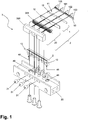
- FIG. 1 are on a support member 30, two mounting jaws 20, which may also be referred to as cooling jaws and / or jaws mounted.
- the fastening jaws 20 are part of a fastening device 2 for horizontal attachment of laser diode bars 100, 101, 102, 103 arranged side by side in a row.
- the fastening jaws 20 are liquid-cooled with a cooling medium and have at least one liquid inlet 40 and at least one liquid outlet 41 There may also be multiple fluid inlets and / or drains.
- a cooling medium water or a special cooling fluid can be used as a cooling medium.
- the mounting jaws 20 each consist of a body 200 and a heat exchange surface 201.
- the body 200 serves the defined cooling water flow and the heat exchange surface 201 represents the external contact to the component to be cooled.
- the heat exchange surface 201 may be designed as a PIN-FIN cooler or as a micro channel cooler.
- the material of the body 200 of the mounting jaws 20 can be made both metallic, for example, copper, copper alloys or aluminum and non-metallic, for example, AIN, BeO or diamond.
- the body 200 of the mounting jaw 20 can be produced mechanically by, for example, turning and / or milling and / or drilling and / or hoisting and / or lapping and / or in the sintering process by, for example, laser sintering and / or in the casting process by, for example, metal casting.
- the heat exchange surface 201 which may be a heat exchange plate, may be manufactured by the same processes and manufactured by forming processes such as embossing or microembossing, respectively.
- cooling insulator elements 10 are applied on the heat exchange surface 201 of the two mounting jaws 20 .
- the cooling insulator elements 10 are part of a holding device 1 for holding laser diode bars 100, 101, 102, 103.
- the heat exchange surface 201 receives first a high-precision machining, for example, diamond milling and / or lapping with the aim of a very flat bearing surface to obtain.
- the object of the cooling insulator elements 10 is to electrically separate the fastening jaw 20 and possibly also the water circuit from the current-carrying part of the laser diode bars 100, 101, 102, 103.
- the cooling insulator element 10 serves to ensure that a very efficient heat transport from the laser diode bars 100, 101, 102, 103 to the fastening jaw 20 takes place.
- a suitable embodiment of the cooling insulator element 10 is a thin diamond plate of suitable dimensions.
- the diamond plate is preferably formed as a synthetically produced diamond platelets.
- the thickness of the diamond plate should be in the range of 50 ⁇ m to 1000 ⁇ m lie. Due to the very good thermal conductivity of synthetic diamond, which is about 1800 W / mK, compared to copper, which is about 400 W / mK, the cooling insulator element 10 leads to a "heat spread" whereby the cooling efficiency of the mounting jaw 20 substantially is increased.
- Ductile metallic contact lugs 12 are applied to the two cooling insulator elements 10.
- the contact lugs 12 are part of a holding device 1 for holding the laser diode bars 100, 101, 102, 103.
- the contact lugs 12 is a preferred embodiment of a device 11 for clamping the laser diode bars 100, 101, 192, 103.
- the contact lugs 12 serve, on the one hand, for the mechanical clamping of the laser diode bars 100, 101, 102, 103 with a defined contact force and, on the other hand, for the power supply for the laser diode bars 100, 101, 102, 103.
- the contact lugs 12 may preferably be designed as a soft annealed copper strip - preferably with double-sided gold coating. Alternatively, the contact lug 12 may also be applied directly to the cooling insulator element 10. This can be done for example by chemical metallization and / or sputtering.
- the tabs 12 are in communication with external electrical leads 13 or may have
- the body 200, the heat exchange surface 201, the cooling insulator element 10 and the contact lug 12 together form a fastening device 2.
- the multi-element package For mounting the laser diode bars 100, 101, 102, 103, the multi-element package "mounting jaw 20 - cooling insulator element 10 - contact lug 12 - laser diode bars 100, 101, 102, 103 - contact lug 12 - Cooling insulator element 10-mounting jaw 20 "mounted on the support member 30.
- This support member 30 serves for a mechanical attachment of the two outer mounting jaws 20 and allows the mechanical compression of the complete package.
- Two fastening devices 2 the carrier element 30 and the laser diode bars 100, 101, 102, 103 form a laser diode unit 3.
- the laser diode bars 100, 101, 102, 103 press into the ductile material of the contact lug 12 and are mechanically positioned in this way.
- an additional pressing device 31 may be provided.
- the additional pressing device 31 may be provided in the form of screws, in particular in the form of pressure screws. But it is also possible that the pressing device is used temporarily, in particular during the assembly process as an external pressing device 31.
- the laser diode bars 100, 101, 102, 103 can emit the light in a defined manner, what in FIG. 1 is sketched by the corresponding triangles, which symbolize the radiation, and further optimal, uniform cooling of the laser diode bars 100, 101, 102, 103 can be achieved, it is particularly necessary that the laser diode bars 100, 101, 102, 103 flush with the upper end of the contact lugs 12. In particular, it must be prevented that the laser diode bars 100, 101, 102, 103 are skewed, or that the components causing the clamping lie obliquely against the laser diode bars 100, 101, 102, 103.
- the spacer element 50 may be in the form of a thread, such as a nylon thread.
- the required height which corresponds to the height of the laser diode bars 100, 101, 102, 103, can be set via the type of spacer elements 50 used, in particular their thickness.
- the spacer element may be in the form of a strip or a plate, for example made of silicone.
- the support member 30 further serves the cooling water supply, cooling water discharge and cooling water distribution on the two mounting jaws 20th
- the cooling insulator elements 10 should be at least as long as a laser diode ingot 100, 101, 102, 103. Preferably, they have the length of two laser diode bars 100, 101, 102, 103 plus an addition for the mounting distances between the individual laser diode bars 100, 101, 102, 103.
- the cooling insulator element 10 can also have the same length as the sum of all mounted laser diode bars 100, 101, 102, 103 plus all mounting distances between the laser diode bars 100, 101, 102, 103.
- the contact lugs 12 should preferably have the length of two laser diode bars 100, 101, 102, 103 plus an addition for the mounting distances between the individual laser diode bars 100, 101, 102, 103 have.
- the contact lugs 12 may be mounted alternately offset on the two mounting jaws 20, so that a serial electrical wiring of the laser diode bars 100, 101, 102, 103 is achieved.
- the laser diode bars 100, 101, 102, 103 are mounted for this purpose with mutual polarity. In this way, each one P-side of a laser diode bar is electrically connected to the N-side of the adjacent laser diode bar.
- the outer electrical lead 13 is located on one or both of the mounting jaws 20, as in FIG FIG. 1 is shown. With an even number of mounted laser diode bars 100, 101, 102, 103, such as 2, 4, or 6, and so on, the two outer electrical leads are on a mounting jaw 20. With an odd number of mounted laser diodes -Bars 100, 101, 102, 103, for example, 1, 3 or 5 and so on, are the electrical leads on both mounting jaws 20th
- the laser diode bars 100, 101, 102, 103 For mounting the laser diode bars 100, 101, 102, 103, these must be arranged relative to the mounting jaws 20 horizontally with high precision. For this purpose, it is provided to place the laser diode bars 100, 101, 102, 103 with their exit facet on a suitable support plate and to position the attachment jaws 20 via the laser diode bars 100, 101, 102, 103.
- the platen must not cause damage to the extremely delicate exit facets.
- the platen may therefore comprise a metal plate e.g. a polished stainless steel plate or a glass plate.
- the support plate may be provided with additional positioning elements. These may be markings on the platen or suitable stops.
- the laser diode bars 100, 101, 102, 103 may be fixed in position by means of a vacuum device integrated with the platen.
- the horizontal orientation should be better than 5 ⁇ m.
- the distances of the individual laser diodes should be made with an accuracy better than 100 ⁇ m.
- the relative alignment of the facets takes place with an accuracy of better than 5 ⁇ m.
- the final horizontal alignment takes place with the aid of the attachment jaws 20.
- the laser diode bars 100, 101, 102, 103 are fixed by clamping between the two mounting jaws 20. In this case, it is utilized that, depending on the pressurization by the two fastening jaws 20, a deformation of the two ductile contact lugs 12 occurs.
- the laser diode bars 100, 101, 102, 103 are hereby, each individually for themselves, pressed into the easily deformable metal of the contact lugs 12.
- the outer shape of the laser diode bars is impressed into the metal of the contact lug 12. This results in addition to a frictional engagement between the laser diode ingot and the metal of the contact lug 12 in addition to a positive connection between the two elements.
- solder connection technique is that no solder connection has to be used for fastening and cooling the laser diode bars 100, 101, 102, 103.
- Solder joints are always problematic because internal stress is often introduced into the semiconductor material of the laser diode bars 100 by different thermal expansion coefficients of the joining partners involved, which leads to a reduced service life of the laser diode bars 100, 101, 102, 103.
- the solder joint may become fatigued and subsequently fail.
- Another advantage of the clamping technique according to the invention lies in the fact that the laser diode bars 100, 101, 102, 103 of the water flowing through Mounting jaw 20 are electrically isolated. This allows on the one hand the use of non-deionized water and thus the use of cheaper cooling systems.
- the mounting jaws 20 can be realized in different designs, for example via microchannel in metal construction, especially in copper-metal construction, on radiator in metal-sintered construction, on micro-channel cooler in ceramic design, via PIN-FIN cooler in metal or ceramic or conventional manufactured coolers in metal or ceramic construction.
- the clamping of the laser diode bars may alternatively only via the mounting surfaces and / or by externally mounted push-in screws and / or by other pressure and / or Anpress-mechanisms and / or by internally attached tension screws and / or by others Train mechanisms take place.
- the cooling insulator elements 10 can preferably be fastened on the heat exchange surfaces 201 of the fastening jaws 20 exclusively by clamping by means of frictional and / or positive locking.
- one or more cooling insulator element (s) 10 can additionally be fixed on the heat exchange surface 201. This can be done for example by gluing.
- pockets 201 for receiving the adhesive can be introduced on the heat exchange surfaces 201.
- the cooling insulator elements 10 can be attached to the mounting jaws 20 by means of soldering or other permanently or temporarily acting connection technology.
- spacer elements 50 can be arranged parallel to the laser diode bars 100, 101, 102, 103 between the opposing cooling insulator elements 10 and / or contact lugs 12 are inserted.
- the thickness of these spacers must be matched to the thickness of the laser diode bars.
- Another way to improve the cooling performance is not to press the cooling insulator element 10 on the heat exchange surface 201, but to bring it into direct contact with the cooling medium.
- the back of the cooling insulator element 10 should be lapped by the cooling medium.
- the cooling insulator element 10 could be inserted into a corresponding opening of the heat exchange surface 201 or else directly into the fastening jaw 20.
- the cooling insulator element 10 closes the opening in the heat exchange surface 201 or the mounting jaw 20.
- the edges of the cooling insulator element 10 are for this purpose tightly connected to the heat exchange surface 201 or the mounting jaw 20. This connection can be realized by gluing, soldering or a circumferential seal.
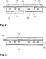
- FIG. 2 an embodiment with a serial interconnection of the individual laser diode bars 100, 101, 102, 103 is shown.
- the laser diode bars 100, 101, 102, 103 are connected in series via contact lugs 12a, 12b, 12c, 12d, 12e.
- two cooling insulator elements 10 are provided on each side of the laser diode bars 100, 101, 102, 103.
- FIG. 3 an embodiment with a parallel interconnection of the individual laser diode bars 100, 101, 102, 103 is shown.
- the laser diode bars 100, 101, 102, 103 are each connected in parallel via contact lugs 12a, 12b.
Landscapes
- Physics & Mathematics (AREA)
- Condensed Matter Physics & Semiconductors (AREA)
- General Physics & Mathematics (AREA)
- Electromagnetism (AREA)
- Optics & Photonics (AREA)
- Semiconductor Lasers (AREA)
Applications Claiming Priority (1)
| Application Number | Priority Date | Filing Date | Title |
|---|---|---|---|
| DE102011009018A DE102011009018A1 (de) | 2011-01-20 | 2011-01-20 | Klemmtechnik für horizontale Montage von Laser-Dioden-Barren |
Publications (2)
| Publication Number | Publication Date |
|---|---|
| EP2485346A2 true EP2485346A2 (fr) | 2012-08-08 |
| EP2485346A3 EP2485346A3 (fr) | 2013-07-31 |
Family
ID=45491461
Family Applications (1)
| Application Number | Title | Priority Date | Filing Date |
|---|---|---|---|
| EP12151677.7A Withdrawn EP2485346A3 (fr) | 2011-01-20 | 2012-01-19 | Technique de pincement pour montage horizontal de barres de diodes laser |
Country Status (2)
| Country | Link |
|---|---|
| EP (1) | EP2485346A3 (fr) |
| DE (1) | DE102011009018A1 (fr) |
Cited By (4)
| Publication number | Priority date | Publication date | Assignee | Title |
|---|---|---|---|---|
| CN112154580A (zh) * | 2018-05-21 | 2020-12-29 | 松下知识产权经营株式会社 | 半导体激光装置 |
| CN113540961A (zh) * | 2020-04-20 | 2021-10-22 | 山东华光光电子股份有限公司 | 一种用于C-mount激光器焊线的激光器固定装置及固定方法 |
| US11557874B2 (en) * | 2021-05-18 | 2023-01-17 | Trumpf Photonics, Inc. | Double-sided cooling of laser diodes |
| US11876343B2 (en) | 2021-05-18 | 2024-01-16 | Trumpf Photonics, Inc. | Laser diode packaging platforms |
Families Citing this family (1)
| Publication number | Priority date | Publication date | Assignee | Title |
|---|---|---|---|---|
| DE102018210139B4 (de) | 2018-06-21 | 2021-02-18 | Trumpf Photonics, Inc. | Diodenlaseranordnung und DWM-Modul mit einer solchen Diodenlaseranordnung |
Citations (5)
| Publication number | Priority date | Publication date | Assignee | Title |
|---|---|---|---|---|
| US5913108A (en) | 1998-04-30 | 1999-06-15 | Cutting Edge Optronics, Inc. | Laser diode packaging |
| US5978396A (en) | 1995-07-13 | 1999-11-02 | Thomson-Csf | Semiconductor laser source |
| US6151341A (en) | 1997-05-30 | 2000-11-21 | Excel/Quantronix, Inc. | Stackable integrated diode packaging |
| US6245589B1 (en) | 1996-11-22 | 2001-06-12 | Fujitsu Limited | Fabrication of cooling device of a planar light source |
| EP1341275B1 (fr) | 2002-02-18 | 2009-08-26 | Monocrom | Module laser |
Family Cites Families (10)
| Publication number | Priority date | Publication date | Assignee | Title |
|---|---|---|---|---|
| US20020110165A1 (en) * | 2001-02-14 | 2002-08-15 | Filgas David M. | Method and system for cooling at least one laser diode with a cooling fluid |
| US6650668B2 (en) * | 2001-10-02 | 2003-11-18 | Coherent, Inc. | Cylindrical two-dimensional diode-laser arrays and method for making same |
| JP2004186212A (ja) * | 2002-11-29 | 2004-07-02 | Sony Corp | 半導体レーザーアレイ装置 |
| JP4037815B2 (ja) * | 2003-09-29 | 2008-01-23 | オムロンレーザーフロント株式会社 | レーザダイオードモジュール、レーザ装置、及びレーザ加工装置 |
| US20080025361A1 (en) * | 2006-07-19 | 2008-01-31 | Jerman John H | Linear diode-laser array with series-connected emitters |
| US7686224B2 (en) * | 2006-08-30 | 2010-03-30 | Coherent, Inc. | Lensed dual diode-laser bar package |
| WO2009049799A1 (fr) * | 2007-10-09 | 2009-04-23 | Jenoptik Laserdiode Gmbh | Barreaux de diode laser raccordés électriquement en série sur un corps métallique de refroidissement |
| DE102008027468B4 (de) * | 2008-06-06 | 2012-10-18 | Jenoptik Laser Gmbh | Wärmeübertragungsvorrichtung mit einem Halbleiterbauelement sowie Anschlussvorrichtung für ihren Betrieb |
| AT508356B1 (de) * | 2009-06-29 | 2011-01-15 | Trumpf Maschinen Austria Gmbh | Vorrichtung und verfahren zum biegen eines werkstücks |
| DE102009040835A1 (de) * | 2009-09-09 | 2011-03-10 | Jenoptik Laserdiode Gmbh | Verfahren zum thermischen Kontaktieren einander gegenüberliegender elektrischer Anschlüsse einer Halbleiterbauelement-Anordnung |
-
2011
- 2011-01-20 DE DE102011009018A patent/DE102011009018A1/de not_active Ceased
-
2012
- 2012-01-19 EP EP12151677.7A patent/EP2485346A3/fr not_active Withdrawn
Patent Citations (5)
| Publication number | Priority date | Publication date | Assignee | Title |
|---|---|---|---|---|
| US5978396A (en) | 1995-07-13 | 1999-11-02 | Thomson-Csf | Semiconductor laser source |
| US6245589B1 (en) | 1996-11-22 | 2001-06-12 | Fujitsu Limited | Fabrication of cooling device of a planar light source |
| US6151341A (en) | 1997-05-30 | 2000-11-21 | Excel/Quantronix, Inc. | Stackable integrated diode packaging |
| US5913108A (en) | 1998-04-30 | 1999-06-15 | Cutting Edge Optronics, Inc. | Laser diode packaging |
| EP1341275B1 (fr) | 2002-02-18 | 2009-08-26 | Monocrom | Module laser |
Cited By (8)
| Publication number | Priority date | Publication date | Assignee | Title |
|---|---|---|---|---|
| CN112154580A (zh) * | 2018-05-21 | 2020-12-29 | 松下知识产权经营株式会社 | 半导体激光装置 |
| JPWO2019225128A1 (ja) * | 2018-05-21 | 2021-06-17 | パナソニックIpマネジメント株式会社 | 半導体レーザ装置 |
| EP3799229A4 (fr) * | 2018-05-21 | 2021-07-14 | Panasonic Intellectual Property Management Co., Ltd. | Dispositif laser à semi-conducteur |
| JP7186345B2 (ja) | 2018-05-21 | 2022-12-09 | パナソニックIpマネジメント株式会社 | 半導体レーザ装置 |
| CN113540961A (zh) * | 2020-04-20 | 2021-10-22 | 山东华光光电子股份有限公司 | 一种用于C-mount激光器焊线的激光器固定装置及固定方法 |
| CN113540961B (zh) * | 2020-04-20 | 2022-06-07 | 山东华光光电子股份有限公司 | 一种用于C-mount激光器焊线的激光器固定装置及固定方法 |
| US11557874B2 (en) * | 2021-05-18 | 2023-01-17 | Trumpf Photonics, Inc. | Double-sided cooling of laser diodes |
| US11876343B2 (en) | 2021-05-18 | 2024-01-16 | Trumpf Photonics, Inc. | Laser diode packaging platforms |
Also Published As
| Publication number | Publication date |
|---|---|
| EP2485346A3 (fr) | 2013-07-31 |
| DE102011009018A1 (de) | 2012-08-09 |
Similar Documents
| Publication | Publication Date | Title |
|---|---|---|
| EP1977486B1 (fr) | Support pour un dispositif vertical de diodes laser avec butée | |
| EP2143139B1 (fr) | Boîte de refroidissement pour composants ou circuits | |
| DE102008026801B4 (de) | Wärmeübertragungsvorrichtung zur doppelseitigen Kühlung eines Halbleiterbauelementes und Verfahren zu seiner Montage | |
| EP2701190B1 (fr) | Procédé de fabrication d'un corps de refroidissement pour au moins un élément à refroidir | |
| EP2324544B1 (fr) | Dispositif de transfert thermique permettant le refroidissement bilatéral d'un dispositif à semi-conducteur | |
| WO2010136017A1 (fr) | Unité modulaire électrique refroidie | |
| DE19506093A1 (de) | Diodenlaserbauelement | |
| DE102013207804A1 (de) | Leistungsmodul mit direkt verbundenen, wärmeleitenden strukturen | |
| EP2485346A2 (fr) | Technique de pincement pour montage horizontal de barres de diodes laser | |
| DE102008027468B4 (de) | Wärmeübertragungsvorrichtung mit einem Halbleiterbauelement sowie Anschlussvorrichtung für ihren Betrieb | |
| WO2022128340A1 (fr) | Procédé de fabrication d'un ensemble électronique, ensemble électronique et véhicule automobile | |
| DE102010041714A1 (de) | Leistungshalbleitermodul und Verfahren zur Herstellung eines Leistungshalbleitermoduls | |
| EP3555913B1 (fr) | Module à semi-conducteur avec tolérance de concavité | |
| DE19956565B4 (de) | Verfahren zum Herstellen einer Wärmesenke für elektrische Bauelemente | |
| DE102015122250A1 (de) | Multifunktionale Modulverbindungsstruktur | |
| EP1959528B1 (fr) | Système de laser à diodes ainsi que procédé de fabrication d'un tel système | |
| DE10229712A1 (de) | Halbleitermodul | |
| DE102012207470B3 (de) | Verfahren zur herstellung einer halbleitermodulanordnung | |
| DE102008061309A1 (de) | Diodenlaserbauelement | |
| WO2009049799A1 (fr) | Barreaux de diode laser raccordés électriquement en série sur un corps métallique de refroidissement | |
| WO2019243322A1 (fr) | Système laser à diode et procédé de fabrication d'un système laser à diode | |
| DE10229711A1 (de) | Halbleitermodul | |
| DE102019115573B4 (de) | Leistungselektronische Schalteinrichtung und Verfahren zur Herstellung | |
| EP0570392A1 (fr) | Configuration de composants degageant de la chaleur dans un dispositif refroidi par un liquide | |
| EP4636823A2 (fr) | Dispositif de refroidissement |
Legal Events
| Date | Code | Title | Description |
|---|---|---|---|
| PUAI | Public reference made under article 153(3) epc to a published international application that has entered the european phase |
Free format text: ORIGINAL CODE: 0009012 |
|
| AK | Designated contracting states |
Kind code of ref document: A2 Designated state(s): AL AT BE BG CH CY CZ DE DK EE ES FI FR GB GR HR HU IE IS IT LI LT LU LV MC MK MT NL NO PL PT RO RS SE SI SK SM TR |
|
| AX | Request for extension of the european patent |
Extension state: BA ME |
|
| PUAL | Search report despatched |
Free format text: ORIGINAL CODE: 0009013 |
|
| AK | Designated contracting states |
Kind code of ref document: A3 Designated state(s): AL AT BE BG CH CY CZ DE DK EE ES FI FR GB GR HR HU IE IS IT LI LT LU LV MC MK MT NL NO PL PT RO RS SE SI SK SM TR |
|
| AX | Request for extension of the european patent |
Extension state: BA ME |
|
| RIC1 | Information provided on ipc code assigned before grant |
Ipc: H01S 5/40 20060101AFI20130627BHEP Ipc: H01S 5/022 20060101ALI20130627BHEP |
|
| STAA | Information on the status of an ep patent application or granted ep patent |
Free format text: STATUS: THE APPLICATION IS DEEMED TO BE WITHDRAWN |
|
| 18D | Application deemed to be withdrawn |
Effective date: 20140201 |