EP2485362A1 - Système et procédé d'établissement d'une compatibilité entre rechargement par fil et rechargement sans fil - Google Patents
Système et procédé d'établissement d'une compatibilité entre rechargement par fil et rechargement sans fil Download PDFInfo
- Publication number
- EP2485362A1 EP2485362A1 EP10791173A EP10791173A EP2485362A1 EP 2485362 A1 EP2485362 A1 EP 2485362A1 EP 10791173 A EP10791173 A EP 10791173A EP 10791173 A EP10791173 A EP 10791173A EP 2485362 A1 EP2485362 A1 EP 2485362A1
- Authority
- EP
- European Patent Office
- Prior art keywords
- unit
- charging unit
- power management
- charging
- wired
- Prior art date
- Legal status (The legal status is an assumption and is not a legal conclusion. Google has not performed a legal analysis and makes no representation as to the accuracy of the status listed.)
- Withdrawn
Links
Images
Classifications
-
- H—ELECTRICITY
- H02—GENERATION; CONVERSION OR DISTRIBUTION OF ELECTRIC POWER
- H02J—ELECTRIC POWER NETWORKS; CIRCUIT ARRANGEMENTS OR SYSTEMS FOR SUPPLYING OR DISTRIBUTING ELECTRIC POWER; SYSTEMS FOR STORING ELECTRIC ENERGY
- H02J7/00—Circuit arrangements for charging or discharging batteries or for supplying loads from batteries
- H02J7/02—Circuit arrangements for charging or discharging batteries or for supplying loads from batteries for charging batteries from AC mains by converters
-
- H—ELECTRICITY
- H02—GENERATION; CONVERSION OR DISTRIBUTION OF ELECTRIC POWER
- H02J—ELECTRIC POWER NETWORKS; CIRCUIT ARRANGEMENTS OR SYSTEMS FOR SUPPLYING OR DISTRIBUTING ELECTRIC POWER; SYSTEMS FOR STORING ELECTRIC ENERGY
- H02J7/00—Circuit arrangements for charging or discharging batteries or for supplying loads from batteries
Definitions
- the disclosure relates to a technique for charging a terminal, and more particularly, to a system and method for enabling compatibility of wired charging with wireless charging.
- terminals have found an increasingly wide utilization in various aspects. Also, the terminals have become rich featured and various entertainments are involved.
- a terminal can be used to listen to music, watch TV or access to the Internet. Due to capacity limitation of a battery in a terminal, the terminal may run out of power after being used for a time period. As a result, the user of the terminal has to charge the battery frequently.
- a terminal may be charged in wired and wireless manners at the same time.
- a system currently used to charge a terminal includes a wired charging unit and a wireless charting unit, which charge a terminal using their respective charging circuits, such that the battery of the terminal may be charged in the wired and wireless manners at the same time within a allowable safe range of the battery.
- the existing system architecture has lead to the following two problems:
- a system for enabling compatibility of wired charging with wireless charging includes a wireless charging unit, a wired charging unit and a power management unit.
- the system further includes an interface circuit.
- the interface circuit is configured to connect both the wired charging unit and the wireless charging unit to the power management unit.
- the wired charging unit is connected to the power management unit via the interface circuit and is configured to charge the power management unit by using a charging circuit in the power management unit.
- the wireless charging unit is connected to the power management unit via the interface circuit and is configured to charge the power management unit by using the same charging circuit as that used by the wired charging unit.
- the wired charging unit may be further configured to charge the power management unit via the interface circuit so as to cause a charging state to be normally entered and to be displayed, where there is an output from the wired charging unit and no output from the wireless charging unit.
- the wireless charging unit may be further configured to charge the power management unit via the interface circuit so as to cause a charging state to be normally entered and to be displayed, where there is an output from the wireless charging unit and no output from the wired charging unit.
- the wireless charging unit may be further configured to autonomously turn off an output from the wireless charging unit in response to detection of an access signal of the wired charging unit from the interface circuit, where there are outputs from both the wireless charging unit and from the wired charging unit.
- the wired charging unit may be further configured to charge the power management unit via the interface circuit so as to cause a charging state to be normally entered and to be displayed, after the wireless charging unit enters a no output state.
- a method for enabling compatibility of wired charging with wireless charging includes that an interface circuit connects both a wired charging unit and a wireless charging unit to a power management unit; and the wireless charging unit and the wired charging unit use a same charging circuit in the power management unit to charge the power management unit.
- the interface circuit may be a path for charging the power management unit by the wired charging unit and the wireless charging unit.
- the charging the power management unit may include: where there is an output from the wired charging unit and no output from the wireless charging unit, the wired charging unit charges the power management unit via the interface circuit so as to cause a charging state to be normally entered and to be displayed.
- the charging the power management unit may include: where there is an output from the wireless charging unit and no output from the wired charging unit, the wireless charging unit charges the power management unit via the interface circuit so as to cause a charging state to be normally entered and to be displayed.
- the charging the power management unit may include: where there are outputs from both the wireless charging unit and the wired charging unit, the wireless charging unit autonomously turns off the output from the wireless charging unit in response to detection of an access signal of the wired charging unit from the interface circuit; and after the wireless charging unit enters a no output state, the wired charging unit charges the power management unit via the interface circuit so as to cause a charging state to be normally entered and to be displayed.
- the system according to the disclosure further includes an interface circuit configured to connect both a wired charging unit and a wireless charging unit to a power management unit, the wired charging unit connected to the power management unit via the interface circuit and configured to charge the power management unit by using a charging circuit in the power management unit, and the wireless charging unit connected to the power management unit via the interface circuit and configured to charge the power management unit by using the same charging circuit as that used by the wired charging unit.
- both the wireless charging unit and the wired charging unit can be connected to the power management unit to charge the power management unit, and thus no matter wired or wireless charging is employed, the charging state may be displayed in the terminal.
- the system according to the disclosure further includes an interface circuit, which is configured to connect a wired charging unit and a wireless charging unit to a power management unit, wherein the wired charging unit is connected to the power management unit via the interface circuit , and is configured to charge the power management unit by using a charging circuit in the power management unit; and the wireless charging unit is connected to the power management unit via the interface circuit, and is configured to charge the power management unit by using the same charging circuit as that used by the wired charging unit.
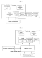
- a system for enabling compatibility of wired charging with wireless charging includes: a wireless charging unit, a wired charging unit and a power management unit.
- the system further includes an interface circuit.
- the power management unit may be arranged in a terminal such as a mobile phone terminal.
- the power management unit may include a charging circuit.
- the other components in the system except for the interface circuit are existing and will not be explained here in detail, and only the changes made herein on the existing components will be explained below.
- the interface circuit is configured to connect both the wired charging unit and the wireless charging unit to the power management unit.
- the wired charging unit is connected to the power management unit via the interface circuit, and is configured to charge the power management unit by using the charging circuit in the power management unit.
- the wireless charging unit is connected to the power management unit via the interface circuit and is configured to charge the power management unit by using the same charging circuit as that used by the wired charging unit.
- Case 1 there is an output from the wired charging unit and no output from the wireless charging unit.
- the wired charging unit is further configured to charge the power management unit via the interface circuit so as to cause a charging state to be normally entered and to be displayed, where there is an output from the wired charging unit and no output from the wireless charging unit.
- Case 2 there is an output from the wireless charging unit and no output from the wired charging unit.
- the wireless charging unit is further configured to charge the power management unit via the interface circuit so as to cause a charging state to be normally entered and to be displayed, where there is an output from the wireless charging unit and no output from the wired charging unit.
- Case 3 there are outputs from both the wireless charging unit and the wired charging unit.
- the wireless charging unit is further configured to autonomously turn off an output from the wireless charging unit in response to detection of an access signal of the wired charging unit from the interface circuit, where there are outputs from both the wireless charging unit and from the wired charging unit. Accordingly, there is no output from the wireless charging unit.
- the wireless charging unit can be switched from an outputting state to a no output state and thus enters the no output state.
- the wired charging unit is further configured to charge the power management unit via the interface circuit so as to cause a charging state to be normally entered and to be displayed, after the wireless charging unit enters the no output state.
- a method for enabling compatibility of wired charging with wireless charging includes the following steps:
- Step 102 The specific processes carried out in Step 102 in different cases are described below:
- Step 102 the specific processes carried out in Step 102 include: the wired charging unit charges the power management unit via the interface circuit so as to cause a charging state to be normally entered and to be displayed.
- Case 2 there is an output from the wireless charging unit and no output from the wired charging unit.
- Step 102 the specific processes carried out in Step 102 include: the wireless charging unit charges the power management unit via the interface circuit so as to cause a charging state to be normally entered and to be displayed.
- Case 3 there are outputs from both the wireless charging unit and the wired charging unit.
- Step 102 the specific processes carried out in Step 102 include the following steps:
- the technical scheme of the disclosure provides a method for enabling compatibility of a wireless charging function with an existing terminal circuit, which may charge the terminal conveniently using the wireless charging function without affecting the wired charging function.
- the disclosure mainly includes the following contents.
- the systemic architecture includes: a wired charging unit, a wireless charging unit, a power management unit and an interface circuit.
- the power management unit may be arranged in a terminal, which may also include a base band circuit, a radio frequency unit and a battery.
- the power management unit includes a charging circuit; the wired charging unit transfers power to the power management unit in a wired transmission manner; the wireless charging unit transfers power to the power management unit in a wireless transmission manner; and the interface circuit is a path for powering the power management unit by the wired charging unit and the wireless charging unit.
- the disclosure mainly includes the following contents.
- the method provided herein enables compatibility of a wireless charging function with an existing terminal circuit can implement both wired and wireless charging functions in a terminal, avoids a conflict that may otherwise exist between a wired charging unit for performing the wired charging function and a wireless charging unit for performing the wireless charging function, and enables the display of a charging state for either a wired charging process or a wireless charging process.
- the wired charging unit charges the power management unit in the terminal via the interface circuit so that the terminal may be normally charged and display a charging state.
- the wireless charging unit charges the power management unit in the terminal via the interface circuit so that the terminal may be normally charged and display the charging state.
- the wireless charging unit detects a signal indicating that the wired charging unit is accessing from the interface circuit, the wireless charging unit autonomously turns off the wireless charging unit, such that no output would issue from the wireless charging unit.
- the wired charging unit powers the power management unit in the terminal via the interface circuit. That is, only the wired charging unit in the interface circuit supplies power to the power management unit in the terminal, such that the terminal may be normally charged and display the charging state.
- the charging process of inputting outputs from both the wired charging unit and the wireless charging unit to the interface circuit includes the following contents:
- the system and method provided herein effectively enable the circuit compatibility of wired charging with wireless charging, such that no conflict occurs between the wired charging unit and the wireless charging unit, for a terminal having both functions of wired charging and wireless charging.
- both the wired charging unit and the wireless charging unit use the same charging circuit to charge a terminal, it is guaranteed that only one circuit is used during a charging process, thus avoiding hidden dangers and prolonging the service life of the battery in the terminal; on the other hand, both the wired charging unit and the wireless charging unit are connected to the power management unit via the same interface circuit. Therefore, no matter which charging manner is employed, wireless charging or wired charging, the charging state may be displayed on the terminal, such that it is convenient for a user to use the terminal and the user experience may be improved.
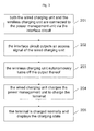
- FIG. 3 An embodiment for the method As shown in Fig. 3 , this embodiment illustrates a charging flow carried out when both a wired charging unit and a wireless charging unit output access signals. This flow includes the following steps:
- the power management unit described above can be represented as PMU.
- the wired charging unit is superior in priority to the wireless charging unit, that is, the wired charging unit is a preferred choice for charging the terminal, in the case where both the wired charging unit and the wireless charging unit output access signals, the wireless charging unit generally carries out a detection operation and then turns off the output thereof autonomously so as to enable the wired charging unit with a higher priority to charge the terminal.
Landscapes
- Engineering & Computer Science (AREA)
- Power Engineering (AREA)
- Charge And Discharge Circuits For Batteries Or The Like (AREA)
- Image Processing (AREA)
Applications Claiming Priority (2)
| Application Number | Priority Date | Filing Date | Title |
|---|---|---|---|
| CN200910224256A CN101707384A (zh) | 2009-11-25 | 2009-11-25 | 一种兼容有线充电和无线充电的系统及方法 |
| PCT/CN2010/071051 WO2010148667A1 (fr) | 2009-11-25 | 2010-03-15 | Système et procédé d'établissement d'une compatibilité entre rechargement par fil et rechargement sans fil |
Publications (2)
| Publication Number | Publication Date |
|---|---|
| EP2485362A1 true EP2485362A1 (fr) | 2012-08-08 |
| EP2485362A4 EP2485362A4 (fr) | 2013-12-18 |
Family
ID=42377585
Family Applications (1)
| Application Number | Title | Priority Date | Filing Date |
|---|---|---|---|
| EP10791173.7A Withdrawn EP2485362A4 (fr) | 2009-11-25 | 2010-03-15 | Système et procédé d'établissement d'une compatibilité entre rechargement par fil et rechargement sans fil |
Country Status (4)
| Country | Link |
|---|---|
| US (1) | US8957632B2 (fr) |
| EP (1) | EP2485362A4 (fr) |
| CN (1) | CN101707384A (fr) |
| WO (1) | WO2010148667A1 (fr) |
Cited By (3)
| Publication number | Priority date | Publication date | Assignee | Title |
|---|---|---|---|---|
| EP2752958A3 (fr) * | 2013-01-08 | 2017-02-08 | LG Electronics Inc. | Transmission d'energie sans file pour terminal mobile |
| WO2019009969A1 (fr) * | 2017-07-06 | 2019-01-10 | Qualcomm Incorporated | Détection de priorité intelligente pour une charge filaire et sans fil |
| CN111049206A (zh) * | 2018-10-15 | 2020-04-21 | 中兴通讯股份有限公司 | 一种充电控制方法及装置、设备、存储介质 |
Families Citing this family (46)
| Publication number | Priority date | Publication date | Assignee | Title |
|---|---|---|---|---|
| US8704484B2 (en) * | 2010-05-28 | 2014-04-22 | Qualcomm Incorporated | Temperature sensor interface for wireless and wired charging |
| JP5348183B2 (ja) * | 2010-08-18 | 2013-11-20 | 三洋電機株式会社 | 電池内蔵機器と充電装置 |
| KR101261338B1 (ko) * | 2011-06-10 | 2013-05-06 | 주식회사 한림포스텍 | 무접점 및 접점 겸용 충전 장치 및 그 제어 방법 |
| JP6039189B2 (ja) | 2012-02-10 | 2016-12-07 | キヤノン株式会社 | 電子機器 |
| KR101920236B1 (ko) * | 2012-06-19 | 2018-11-20 | 삼성전자주식회사 | 배터리를 충전하기 위한 방법 및 그 전자 장치 |
| KR102158288B1 (ko) * | 2012-07-09 | 2020-09-21 | 삼성전자주식회사 | 배터리를 충전하기 위한 방법 및 그 전자 장치 |
| JP5942688B2 (ja) * | 2012-08-08 | 2016-06-29 | 富士通株式会社 | 電子機器、充電制御方法、及び充電制御プログラム |
| US9434263B2 (en) * | 2012-09-05 | 2016-09-06 | Lear Corporation | Multi-mode battery charger |
| CN102983613A (zh) * | 2012-11-30 | 2013-03-20 | 邹小兰 | 一种无线充电装置 |
| CN103002158A (zh) * | 2012-12-21 | 2013-03-27 | 东莞宇龙通信科技有限公司 | 终端和终端充电的管理方法 |
| KR20140086000A (ko) * | 2012-12-28 | 2014-07-08 | 삼성전자주식회사 | 유무선 충전이 가능한 휴대 단말기 및 그의 충전 방법 |
| CN104065145B (zh) * | 2013-03-20 | 2018-06-19 | 深圳富泰宏精密工业有限公司 | 无线充电装置及其充电方法 |
| US9381821B2 (en) | 2013-05-15 | 2016-07-05 | Qualcomm Incorporated | Systems, methods, and apparatus related to electric vehicle wired and wireless charging |
| CN103259315B (zh) * | 2013-05-31 | 2015-04-22 | 苏州源辉电气有限公司 | 电动汽车充放电开关、其控制电路以及控制方法 |
| CN103532198B (zh) * | 2013-10-24 | 2017-01-18 | 小米科技有限责任公司 | 充电控制电路、芯片、充电电路、接收端和终端设备 |
| CN104704704B (zh) * | 2014-03-04 | 2017-09-19 | 华为终端有限公司 | 一种充电电路和终端 |
| CN103887571A (zh) * | 2014-03-28 | 2014-06-25 | 乐视致新电子科技(天津)有限公司 | 一种充电方式切换方法及装置 |
| CN103956784B (zh) * | 2014-04-15 | 2016-01-20 | 国家电网公司 | 一种电动汽车无线与有线充电切换装置 |
| US20150303704A1 (en) * | 2014-04-16 | 2015-10-22 | Mediatek Inc. | Charging system automatically switching between wired charging mode and wireless charging mode, and related charging control method and wireless power receiver circuit |
| CN103997101B (zh) * | 2014-06-12 | 2019-07-09 | 青岛海信移动通信技术股份有限公司 | 一种充电电路及一种电子设备 |
| KR101681376B1 (ko) * | 2014-10-10 | 2016-11-30 | 삼성전기주식회사 | 전력 공급 장치 |
| CN105790336A (zh) * | 2014-12-24 | 2016-07-20 | 比亚迪股份有限公司 | 车载终端充电系统及汽车 |
| JP6516491B2 (ja) * | 2015-01-30 | 2019-05-22 | キヤノン株式会社 | 通信装置、制御方法およびプログラム |
| US20170080817A1 (en) * | 2015-09-21 | 2017-03-23 | Ford Global Technologies, Llc | System and method for charging electrified vehicles |
| CN105656115B (zh) * | 2015-11-30 | 2019-05-14 | 东莞酷派软件技术有限公司 | 一种双通道充电方法、系统和终端 |
| CN105958563A (zh) * | 2016-04-27 | 2016-09-21 | 珠海格力电器股份有限公司 | 用于充电模式切换的系统以及充电模式切换方法 |
| CN106364355B (zh) * | 2016-10-12 | 2018-11-13 | 山东大学 | 一种电动汽车无线与交流联合充电系统及其方法 |
| WO2018072209A1 (fr) * | 2016-10-21 | 2018-04-26 | 北京小米移动软件有限公司 | Procédé de charge et dispositif électronique |
| CN106385077B (zh) * | 2016-10-28 | 2019-07-12 | 努比亚技术有限公司 | 充电控制方法及装置 |
| CN106684978A (zh) * | 2016-12-19 | 2017-05-17 | 宇龙计算机通信科技(深圳)有限公司 | 一种充电电路、充电电路的充电控制方法及终端 |
| CN106786907A (zh) * | 2016-12-26 | 2017-05-31 | 广东欧珀移动通信有限公司 | 一种充电电路、方法以及终端 |
| KR20180104381A (ko) * | 2017-03-13 | 2018-09-21 | 삼성전자주식회사 | 전원 공급 장치와 이를 포함하는 디스플레이 시스템 및 전원 공급 장치의 전원 선택 방법 |
| WO2019041089A1 (fr) * | 2017-08-28 | 2019-03-07 | 深圳传音通讯有限公司 | Adaptateur de charge sans fil et procédé de charge correspondant |
| CN108288878A (zh) * | 2017-12-29 | 2018-07-17 | 上海挚想科技有限公司 | 充电方法及充电装置 |
| CN108988440B (zh) * | 2018-09-03 | 2020-07-17 | Oppo广东移动通信有限公司 | 充电电路、电子设备及充电方法 |
| CN109066880A (zh) * | 2018-09-03 | 2018-12-21 | 楼夏春 | 触屏式移动电源 |
| CN113169575A (zh) * | 2018-12-21 | 2021-07-23 | Oppo广东移动通信有限公司 | 充电装置、待充电设备、充电方法及计算机存储介质 |
| KR102676498B1 (ko) * | 2019-02-19 | 2024-06-20 | 삼성전자 주식회사 | 무선 전력 공유에 따른 사용자 인터페이스 제공 방법 및 장치 |
| CN110525247B (zh) * | 2019-08-27 | 2021-11-23 | 中兴新能源汽车有限责任公司 | 一种充电电路、方法及设备 |
| CN110783984B (zh) * | 2019-10-30 | 2023-11-07 | 歌尔科技有限公司 | 充电盒及其充电控制方法、可读存储介质 |
| US20230198318A1 (en) * | 2020-01-20 | 2023-06-22 | Lg Electronics Inc. | Wireless power reception device, wireless power reception method, and wireless charging service providing method |
| CN112994164B (zh) * | 2021-03-16 | 2022-05-13 | 深圳爱科思达科技有限公司 | 一种车载充电器 |
| CN115117948A (zh) * | 2021-03-22 | 2022-09-27 | 北京小米移动软件有限公司 | 充电系统、充电控制方法、装置、电子设备及存储介质 |
| CN114243879B (zh) * | 2021-12-23 | 2022-10-21 | 深圳市鑫嘉恒科技有限公司 | 一种太阳能户外电源系统的充电控制方法、系统及计算机可读存储介质 |
| CN114834286A (zh) * | 2022-05-05 | 2022-08-02 | 蓓伟机器人科技(上海)有限公司 | 一种船用无线充电系统及无线充电方法 |
| CN116054350A (zh) * | 2023-02-27 | 2023-05-02 | 维沃移动通信有限公司 | 充电电路和电子设备 |
Family Cites Families (13)
| Publication number | Priority date | Publication date | Assignee | Title |
|---|---|---|---|---|
| US4686444A (en) | 1984-11-21 | 1987-08-11 | Samsung Electronics Co., Ltd. | Battery charging circuit |
| CN1571241A (zh) | 2004-04-28 | 2005-01-26 | 北京汉王科技有限公司 | 一种为电子设备提供能源的装置 |
| US7904113B2 (en) * | 2004-11-12 | 2011-03-08 | Interdigital Technology Corporation | Method and apparatus for detecting and selectively utilizing peripheral devices |
| US20060103355A1 (en) * | 2004-11-16 | 2006-05-18 | Joseph Patino | Method and system for selectively charging a battery |
| US8169185B2 (en) * | 2006-01-31 | 2012-05-01 | Mojo Mobility, Inc. | System and method for inductive charging of portable devices |
| JP4777155B2 (ja) * | 2006-06-15 | 2011-09-21 | パナソニック株式会社 | 電子機器、非接触型充電器及び非接触充電システム |
| CN200983137Y (zh) | 2006-08-10 | 2007-11-28 | 精模电子科技(深圳)有限公司 | 可充电键盘 |
| WO2008044297A1 (fr) * | 2006-10-11 | 2008-04-17 | Panasonic Corporation | Dispositif électronique et procédé de commande de charge |
| JP4891100B2 (ja) | 2007-01-17 | 2012-03-07 | セイコーエプソン株式会社 | 受電制御装置、受電装置及び電子機器 |
| KR101474421B1 (ko) * | 2007-11-23 | 2014-12-19 | 엘지전자 주식회사 | 충전메뉴 설정기능을 갖는 이동 단말기 및 이를 이용한상호 충전방법 |
| KR101432590B1 (ko) * | 2007-12-12 | 2014-08-21 | 엘지전자 주식회사 | 무선 충전용 메뉴 제공 기능을 갖는 이동 단말기 및 그충전방법 |
| US20110050164A1 (en) * | 2008-05-07 | 2011-03-03 | Afshin Partovi | System and methods for inductive charging, and improvements and uses thereof |
| CN201466761U (zh) | 2009-06-23 | 2010-05-12 | 天津三星光电子有限公司 | 具有无线充电功能的数码相机usb充电器 |
-
2009
- 2009-11-25 CN CN200910224256A patent/CN101707384A/zh active Pending
-
2010
- 2010-03-15 WO PCT/CN2010/071051 patent/WO2010148667A1/fr not_active Ceased
- 2010-03-15 EP EP10791173.7A patent/EP2485362A4/fr not_active Withdrawn
- 2010-03-15 US US13/509,961 patent/US8957632B2/en active Active
Cited By (4)
| Publication number | Priority date | Publication date | Assignee | Title |
|---|---|---|---|---|
| EP2752958A3 (fr) * | 2013-01-08 | 2017-02-08 | LG Electronics Inc. | Transmission d'energie sans file pour terminal mobile |
| WO2019009969A1 (fr) * | 2017-07-06 | 2019-01-10 | Qualcomm Incorporated | Détection de priorité intelligente pour une charge filaire et sans fil |
| US10686330B2 (en) | 2017-07-06 | 2020-06-16 | Qualcomm Incorporated | Smart priority detection for wired and wireless charging |
| CN111049206A (zh) * | 2018-10-15 | 2020-04-21 | 中兴通讯股份有限公司 | 一种充电控制方法及装置、设备、存储介质 |
Also Published As
| Publication number | Publication date |
|---|---|
| CN101707384A (zh) | 2010-05-12 |
| WO2010148667A1 (fr) | 2010-12-29 |
| EP2485362A4 (fr) | 2013-12-18 |
| US8957632B2 (en) | 2015-02-17 |
| US20120229084A1 (en) | 2012-09-13 |
Similar Documents
| Publication | Publication Date | Title |
|---|---|---|
| US8957632B2 (en) | System and method for compatible wired charging and wireless charging | |
| US11750963B2 (en) | Communication control method, device and system, charging box and wireless earpiece | |
| KR102215085B1 (ko) | 충전 기기 및 그 동작 방법 | |
| US9728989B2 (en) | Method for charging battery inside electronic device with a plurality of power supplies and a plurality of charging modules with USB OTG functionality | |
| US9774685B2 (en) | Electronic device, mobile terminal connection control method, and power control program | |
| KR20100072857A (ko) | 휴대 단말기의 인터럽트 제어 방법 및 제어 장치 | |
| JP2012205366A (ja) | 入出力回路 | |
| KR20140120699A (ko) | 충전을 위한 전자 장치 제어 방법 및 이를 지원하는 전자 장치와 충전 장치 | |
| US20140225557A1 (en) | System for performing recharging and data communication | |
| JP2012205007A (ja) | 入出力回路 | |
| WO2012077270A1 (fr) | Dispositif électronique | |
| CN106786961A (zh) | 充电处理方法、装置及终端 | |
| CN113241835B (zh) | 充电模组、电子设备及充电控制方法 | |
| US9502911B2 (en) | Battery charging device with charging profile data update facility | |
| KR20210064736A (ko) | 전자 장치 및 이의 충전 방법 | |
| KR20140122495A (ko) | 배터리 팩 및 배터리 팩의 충전 제어방법 | |
| CN105576753A (zh) | 一种信息处理方法及电子设备 | |
| KR101721202B1 (ko) | 충전시에 광고 콘텐츠가 표시되는 보조 배터리 상태 정보 알림 장치 | |
| JP6087080B2 (ja) | 車載システム | |
| JP2013223269A (ja) | 充電可能な携帯装置 | |
| JP2015144519A (ja) | 情報処理装置及び情報処理装置における処理方法 | |
| JP2015207155A (ja) | 電子装置 | |
| JP2014060861A (ja) | 二次電池の充電装置 | |
| CN111162572B (zh) | 一种电子设备及其充电电路和充电方法 | |
| EP2682872B1 (fr) | Interposeur et multiplexeur intelligent pour fournir plusieurs bus périphériques |
Legal Events
| Date | Code | Title | Description |
|---|---|---|---|
| PUAI | Public reference made under article 153(3) epc to a published international application that has entered the european phase |
Free format text: ORIGINAL CODE: 0009012 |
|
| 17P | Request for examination filed |
Effective date: 20120328 |
|
| AK | Designated contracting states |
Kind code of ref document: A1 Designated state(s): AT BE BG CH CY CZ DE DK EE ES FI FR GB GR HR HU IE IS IT LI LT LU LV MC MK MT NL NO PL PT RO SE SI SK SM TR |
|
| DAX | Request for extension of the european patent (deleted) | ||
| A4 | Supplementary search report drawn up and despatched |
Effective date: 20131115 |
|
| RIC1 | Information provided on ipc code assigned before grant |
Ipc: H02J 7/02 20060101AFI20131111BHEP |
|
| STAA | Information on the status of an ep patent application or granted ep patent |
Free format text: STATUS: THE APPLICATION IS DEEMED TO BE WITHDRAWN |
|
| 18D | Application deemed to be withdrawn |
Effective date: 20140614 |