EP2485887B1 - Presse à tête articulée - Google Patents
Presse à tête articulée Download PDFInfo
- Publication number
- EP2485887B1 EP2485887B1 EP10776771.7A EP10776771A EP2485887B1 EP 2485887 B1 EP2485887 B1 EP 2485887B1 EP 10776771 A EP10776771 A EP 10776771A EP 2485887 B1 EP2485887 B1 EP 2485887B1
- Authority
- EP
- European Patent Office
- Prior art keywords
- head
- press
- support
- spherical joint
- spherical
- Prior art date
- Legal status (The legal status is an assumption and is not a legal conclusion. Google has not performed a legal analysis and makes no representation as to the accuracy of the status listed.)
- Active
Links
Images

Classifications
-
- B—PERFORMING OPERATIONS; TRANSPORTING
- B30—PRESSES
- B30B—PRESSES IN GENERAL
- B30B15/00—Details of, or accessories for, presses; Auxiliary measures in connection with pressing
- B30B15/06—Platens or press rams
- B30B15/068—Drive connections, e.g. pivotal
Definitions
- the present invention relates to a press for the treatment of parts. It is particularly well suited, although not exclusively, to industrial applications for which high loads are necessary, such as for example the manufacture of microelectronic circuits.
- Such an annular spherical joint is formed of a female part which cooperates, with adjustment, with a male part.
- the female part is in the form of a concave spherical inner bearing ring which is mounted on the slider.
- the male part has the shape of a convex spherical outer span ring which is mounted on the press head.
- the annular spherical joint supports small loads, it is, on the other hand, not able to withstand high loads, the ring of the spherical joint deforming under pressure. In the latter case, the centering of the press head relative to the slider is no longer ensured.
- the present invention aims to overcome this disadvantage and, in particular, to provide a press capable of withstanding high loads without deformation.
- the central articulation avoids deformation of the annular hinge, when applying a high load predefined on one or more parts to be treated.
- the predefined load is distributed at the two annular and central spherical joints and not only at the single annular joint. The centering of the press head relative to the slider is thus ensured, whatever the load applied.
- the increase in mass and volume is reduced in comparison with that which would have accompanied the implementation of a single spherical joint formed from, for example, a half-sphere full bulky and heavy.
- said annular and central spherical joints are concentric.
- first planar reference face associated with said orientable head.
- first reference plane face may be a plane contact face of the orientable head opposite the support or even the face of a workpiece disposed on the contact face of the head.
- the press further comprises means for obtaining, without contact, a parallelism between a first reference face, associated with said orientable head, and a second reference face, associated with said support.
- Said means for obtaining a parallelism may comprise at least two controllable actuators, which are mounted on said slider and which are able to rotate said steerable head.
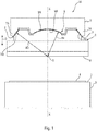
- the figure 1 schematically represents a cross-sectional view of a press according to an embodiment of the present invention.
- the figure 2 is a schematic cross section of a variant according to the invention of the press shown in FIG. figure 1 .
- the figure 3 is a schematic sectional view along the line III-III of the slide of the press illustrated on the figure 2 .
- FIG. 1 there is shown a press 1A for the treatment of parts according to an embodiment of the present invention.
- the press can be either a low-load press or a medium or heavy load press.
- the steerable head 6 may also include a workpiece (not shown) opposite that arranged on the support 2.
- a workpiece (not shown) opposite that arranged on the support 2.
- silicon discs As an illustrative but nonlimiting example, there may be mentioned, as parts to be treated, silicon discs.
- the annular spherical joint 7 makes it possible to obtain a parallelism between a first reference plane face (for example the contact face 8 or the face of a workpiece disposed on the contact face 8) and a second planar face of reference (for example the support face 3 or the face of a workpiece carried by the support face 3), during the contact of these two reference faces, prior to the application of a predetermined load.
- the parallelism of the two reference faces is thus obtained before a stiffening of the spherical joints 7 and 9.
- the annular spherical joint 7 is formed of a female portion 7A which cooperates, with adjustment, with a male portion 7B.
- the female part 7A is in the form of a concave spherical inner bearing ring which is mounted on the slider 5.
- the male part 7B has the shape of a convex spherical outer bearing ring which is mounted on the press head 6.
- the center O of the annular articulation 7 defines a pivot point around which the pivoting head 6 can pivot.
- the slider 5 and the press head 6 comprise respective complementary means 9A and 9B which cooperate directly with one another to form a central spherical articulation 9 which associates with the annular spherical articulation 7 to ensure the pivoting of said press head 6.
- the complementary means comprise a female part 9A and a male part 9B, which cooperate with each other with adjustment.
- the male part 9B is formed of a spherical nipple, mounted on the press head 6, and the female part 9A is in the form of a recess with a spherical bottom formed in the end of the slide 5 facing the support 2.
- the spherical nipple 9B engages in the recess 9A to form the central spherical joint 9.
- the two spherical joints 7 and 9 are concentric, the center O of the central spherical articulation 9 coinciding with that of the annular spherical articulation 7.
- the presence of the spherical nipple 9A increases the contact area between the slider 5 and the press head 6, which reduces the forces on the ring 7A. This prevents a deformation of the latter during the application of a heavy load.
- the radius R1 of the central spherical joint 9 is at most equal to the radius R2 of the spherical joint 7.
- the press 1B is similar to that described in connection with the figure 1 , except that it comprises means for obtaining a parallelism between a first reference face (the contact face 8, the face of a workpiece disposed on the contact face 8, etc.) and the second reference face (the support face 3, the face of a workpiece carried by the support face 3, etc.), prior to contacting the orientable head 6 and the support 2.
- a first reference face the contact face 8, the face of a workpiece disposed on the contact face 8, etc.
- the second reference face the support face 3, the face of a workpiece carried by the support face 3, etc.
- these means are in the form of two controllable actuators 10 coupled to two pusher elements 11, respectively mounted at the periphery of the slider 5.
- the pusher elements 11 are arranged vis-à-vis the actuators 10, diametrically opposite to the reference axis XX. They are also separated from each other by a 90 ° angle.
- Each actuator 10 comprises a finger 10A mounted axially movable in a tubular guide 10B.
- the movement of the finger 10A is controlled by control means (not shown in the figures).
- One of the ends of the finger 10A is in contact with the press head 6.
- the control means of the actuators 10 are independent and may optionally be associated with an optical alignment device by laser sensors (not shown in the figures).
- the pushing elements 11 respectively comprise a bearing finger 11A mounted to be elastically mobile in a tubular guide 11B.
- the ends of the support finger 11A are respectively in contact with the press head 6 and a compression spring 11C housed in the tubular guide 11B. This compression spring 11C exerts an action on the support finger 11A, so that it remains in contact with the press head 6.
Landscapes
- Engineering & Computer Science (AREA)
- Mechanical Engineering (AREA)
- Presses And Accessory Devices Thereof (AREA)
- Control Of Presses (AREA)
Description
- La présente invention concerne une presse destinée au traitement de pièces. Elle est particulièrement bien adaptée, quoique non exclusivement, aux applications industrielles pour lesquelles des fortes charges sont nécessaires, telles que par exemple la fabrication de circuits micro-électroniques.
- Le document
US 2001/0027727 , conforme au préambule de la revendication 1, et le documentUS 2007/0105491 décrivent de telles presses. - On connait déjà des presses à faible charge qui comportent :
- un support de pièces à traiter ;
- un coulisseau mobile transversalement audit support ; et
- une tête de presse orientable articulée audit coulisseau par l'intermédiaire d'une articulation sphérique annulaire, ladite tête étant destinée à être appliquée sur ledit support de pièces par déplacement dudit coulisseau.
- Une telle articulation sphérique annulaire est formée d'une partie femelle qui coopère, avec ajustement, avec une partie mâle. La partie femelle se présente sous la forme d'une bague à portée interne sphérique concave qui est montée sur le coulisseau. La partie mâle a la forme d'un anneau à portée externe sphérique convexe qui est monté sur la tête de presse.
- Bien que l'articulation sphérique annulaire supporte de faibles charges, elle se révèle, en revanche, incapable de résister à des charges élevées, la bague de l'articulation sphérique se déformant sous la pression. Dans ce dernier cas, le centrage de la tête de presse par rapport au coulisseau n'est plus assuré.
- La présente invention a pour objet de remédier à cet inconvénient et, notamment, de fournir une presse apte à résister à des fortes charges sans déformation.
- A cette fin, selon l'invention, la presse destinée au traitement de pièces du type comportant les caractéristiques de la revendication 1 est proposée.
- Ainsi, grâce à l'invention, l'articulation centrale permet d'éviter une déformation de l'articulation annulaire, lors de l'application d'une charge élevée prédéfinie sur une ou plusieurs pièces à traiter. En effet, la charge prédéfinie est répartie au niveau des deux articulations sphériques annulaire et centrale et non plus uniquement au niveau de la seule articulation annulaire. Le centrage de la tête de presse par rapport au coulisseau est ainsi assuré, quelle que soit la charge appliquée.
- En outre, grâce à l'invention, l'augmentation de masse et de volume est réduite en comparaison avec celle qui aurait accompagnée la mise en oeuvre d'une unique articulation sphérique formée à partir, par exemple, d'une demi-sphère pleine volumineuse et lourde.
- De préférence, lesdites articulations sphériques annulaire et centrale sont concentriques.
- En outre, le centre desdites articulations sphériques annulaire et centrale est localisé sur une première face plane de référence associée à ladite tête orientable. Par exemple, la première face plane de référence peut être une face plane de contact de la tête orientable en regard du support ou bien encore la face d'une pièce à traiter disposée sur la face de contact de la tête.
- Dans un mode de réalisation particulier de la présente invention, la presse comporte en outre des moyens pour obtenir, sans contact, un parallélisme entre une première face de référence, associée à ladite tête orientable, et une seconde face de référence, associée audit support.
- Ainsi, on peut réaliser le parallélisme entre les première et seconde faces de référence préalablement à l'application d'une charge déterminée par la presse.
- Lesdits moyens pour obtenir un parallélisme peuvent comporter au moins deux actionneurs commandables, qui sont montés sur ledit coulisseau et qui sont aptes à faire pivoter ladite tête orientable.
- Les figures du dessin annexé feront bien comprendre comment l'invention peut être réalisée. Sur ces figures, des références identiques désignent des éléments semblables.
- La
figure 1 représente, de façon schématique, une vue en coupe transversale d'une presse conforme à un mode de réalisation de la présente invention. - La
figure 2 est une coupe transversale schématique d'une variante conforme à l'invention de la presse représentée enfigure 1 . - La
figure 3 est une vue schématique en coupe, selon la ligne III-III, du coulisseau de la presse illustrée sur lafigure 2 . - Sur la
figure 1 , on a représenté une presse 1A destinée au traitement de pièces conforme à un mode de réalisation de la présente invention. - Dans le cadre de la présente invention, la presse peut aussi bien être une presse à faible charge qu'une presse à moyenne ou forte charge.
- De façon usuelle, la presse comporte :
- un support 2 de pièces à traiter qui peut être fixe ou, au contraire, mobile. Ce support 2 présente une face plane de support 3 apte à recevoir une pièce à traiter 4 ;
- un coulisseau 5 mobile transversalement au support 2. Le déplacement du coulisseau est symbolisé par la double flèche D ; et
- une tête de presse orientable 6 articulée au coulisseau 5 par l'intermédiaire d'une articulation sphérique annulaire 7. Elle présente une face plane de contact 8. Cette tête orientable 6 est destinée à être appliquée sur le support de pièces 2 par déplacement du coulisseau 5.
- La tête orientable 6 peut également comporter une pièce à traiter (non représentée) en regard de celle disposée sur le support 2. A titre d'exemple illustratif mais non limitatif, on peut citer, comme pièces à traiter, des disques de silicium.
- L'articulation sphérique annulaire 7 permet d'obtenir un parallélisme entre une première face plane de référence (par exemple la face de contact 8 ou la face d'une pièce à traiter disposée sur la face de contact 8) et une seconde face plane de référence (par exemple la face de support 3 ou la face d'une pièce à traiter portée par la face de support 3), lors du contact de ces deux faces de référence, préalablement à l'application d'une charge prédéterminée. Le parallélisme des deux faces de référence est ainsi obtenu avant une rigidification des articulations sphériques 7 et 9.
- Comme le montre la
figure 1 , l'articulation sphérique annulaire 7 est formée d'une partie femelle 7A qui coopère, avec ajustement, avec une partie mâle 7B. La partie femelle 7A se présente sous la forme d'une bague à portée interne sphérique concave qui est montée sur le coulisseau 5. La partie mâle 7B a la forme d'un anneau à portée externe sphérique convexe qui est monté sur la tête de presse 6. - Le centre O de l'articulation annulaire 7 définit un point de pivotement autour duquel peut pivoter la tête orientable 6.
- Selon l'invention, comme le montre la
figure 1 , le coulisseau 5 et la tête de presse 6 comportent des moyens complémentaires respectifs 9A et 9B qui coopèrent directement l'un avec l'autre pour former une articulation sphérique centrale 9 qui s'associe à l'articulation sphérique annulaire 7 pour assurer le pivotement de ladite tête de presse 6. - Les moyens complémentaires comportent une partie femelle 9A et une partie mâle 9B, qui coopèrent l'une avec l'autre avec ajustement. La partie mâle 9B est formée d'un téton sphérique, monté sur la tête de presse 6, et la partie femelle 9A se présente sous la forme d'un évidement à fond sphérique pratiqué dans le bout du coulisseau 5 orienté vers le support 2. Le téton sphérique 9B s'engage dans l'évidement 9A pour former l'articulation sphérique centrale 9.
- Dans le cadre de l'invention, les deux articulations sphériques 7 et 9 sont concentriques, le centre O de l'articulation sphérique centrale 9 coïncidant avec celui de l'articulation sphérique annulaire 7.
- La présence du téton sphérique 9A augmente la surface de contact entre le coulisseau 5 et la tête de presse 6, ce qui permet de réduire les efforts sur la bague 7A. On évite ainsi une déformation de cette dernière lors de l'application d'une forte charge.
- On notera que, dans ce mode de réalisation, le rayon R1 de l'articulation sphérique centrale 9 est au plus égal au rayon R2 de l'articulation sphérique 7.
- Dans une variante du mode de réalisation conforme à l'invention, illustrée sur la
figure 2 , la presse 1B est semblable à celle décrite en relation avec lafigure 1 , excepté qu'elle comporte des moyens pour obtenir un parallélisme entre une première face de référence (la face de contact 8, la face d'une pièce à traiter disposée sur la face de contact 8, etc.) et la seconde face de référence (la face de support 3, la face d'une pièce à traiter portée par la face de support 3, etc.), préalablement à la mise en contact de la tête orientable 6 et du support 2. - Comme le montrent les
figures 2 et 3 , ces moyens se présentent sous la forme de deux actionneurs commandables 10 couplés à deux éléments poussoirs 11, respectivement montés en périphérie du coulisseau 5. Les actionneurs 10, disposés à égale distance d'un axe de référence X-X passant par le centre O, sont écartés l'un de l'autre d'un angle de 90°. Les éléments poussoirs 11 sont agencés en vis-à-vis des actionneurs 10, de façon diamétralement opposée par rapport à l'axe de référence X-X. Ils sont donc également écartés l'un de l'autre d'un angle de 90°. - Chaque actionneur 10 comprend un doigt 10A monté axialement mobile dans un guide tubulaire 10B. Le déplacement du doigt 10A est contrôlé par des moyens de commande (non représentés sur les figures). Une des extrémités du doigt 10A est au contact de la tête de presse 6.
- Les moyens de commande des actionneurs 10 sont indépendants et peuvent éventuellement être associés à un dispositif d'alignement optique par capteurs laser (non représenté sur les figures).
- Par ailleurs, les éléments poussoirs 11 comportent respectivement un doigt d'appui 11A monté élastiquement mobile dans un guide tubulaire 11B. Les extrémités du doigt d'appui 11A sont en contact respectivement avec la tête de presse 6 et un ressort de compression 11C logé dans le guide tubulaire 11B. Ce ressort de compression 11C exerce une action sur le doigt d'appui 11A, de sorte que celui-ci reste en contact avec la tête de presse 6.
- En outre, l'action des doigts d'appui 11A sur la tête de presse 6 assure un contact permanent des doigts 10A avec ladite tête 6.
- Ainsi, en commandant le déplacement des doigts 10A des actionneurs 10 (et donc l'inclinaison de la première face de référence selon respectivement des axes d'inclinaison Y-Y et Z-Z, orthogonaux à l'axe de référence X-X), on peut ajuster, sans contact, le parallélisme entre la première face de référence et la seconde face de référence.
Claims (5)
- Presse destinée au traitement de pièces du type comportant :- un support (2) de pièces à traiter ;- un coulisseau (5) mobile transversalement audit support (2) ; et- une tête de presse orientable (6) articulée audit coulisseau (5) par l'intermédiaire d'au moins une articulation sphérique annulaire (7), ladite tête (6) étant destinée à être appliquée sur ledit support de pièces (2) par déplacement (D) dudit coulisseau (5),ledit coulisseau (5) et ladite tête de presse (6) comportant des moyens complémentaires respectifs (9A, 9B) qui coopèrent directement l'un avec l'autre, pour former une articulation sphérique centrale (9) qui s'associe à ladite articulation sphérique annulaire (7) pour assurer le pivotement de ladite tête de presse (6) ; caractérisée en ce que l'articulation sphérique annulaire (7) est formée d'une partie femelle (7A) qui coopère, avec ajustement avec une partie mâle (7B), la partie femelle (7A) se présentant sous la forme d'une bague à portée interne sphérique concave qui est montée sur le coulisseau (5), la partie mâle (7B) ayant la forme d'un anneau à portée externe sphérique convexe qui est monté sur la tête de presse (6) ;
les moyens complémentaires comportant une partie femelle (9A) et une partie mâle (9B) qui coopèrent l'une avec l'autre avec ajustement, la partie mâle (9B) étant formée d'un téton sphérique monté sur la tête de presse (6) et la partie femelle (9A) se présentant sous la forme d'un évidement à fond sphérique pratiqué dans un bout du coulisseau (5) orienté vers le support (2), le téton sphérique (9B) s'engageant dans l'évidement (9A) pour former l'articulation sphérique centrale (9). - Presse selon la revendication 1,
caractérisée en ce que lesdites articulations sphériques annulaire (7) et centrale (9) sont concentriques. - Presse selon la revendication 2,
caractérisée en ce que le centre (O) desdites articulations sphériques annulaire (7) et centrale (9) est localisé sur une première face plane de référence (8) associée à ladite tête orientable (6). - Presse selon l'une des revendications 1 à 3,
caractérisée en ce qu'elle comporte en outre des moyens (10) pour obtenir, sans contact, un parallélisme entre une première face de référence, associée à ladite tête orientable (6), et une seconde face de référence, associée audit support (2). - Presse selon la revendication 4,
caractérisée en ce que lesdits moyens pour obtenir un parallélisme comportent au moins deux actionneurs commandables (10), qui sont montés sur ledit coulisseau (5) et qui sont aptes à faire pivoter ladite tête orientable (6).
Applications Claiming Priority (2)
| Application Number | Priority Date | Filing Date | Title |
|---|---|---|---|
| FR0904804A FR2951106B1 (fr) | 2009-10-08 | 2009-10-08 | Presse a tete articulee |
| PCT/FR2010/052065 WO2011042643A1 (fr) | 2009-10-08 | 2010-09-30 | Presse à tête articulée |
Publications (2)
| Publication Number | Publication Date |
|---|---|
| EP2485887A1 EP2485887A1 (fr) | 2012-08-15 |
| EP2485887B1 true EP2485887B1 (fr) | 2019-08-14 |
Family
ID=42135976
Family Applications (1)
| Application Number | Title | Priority Date | Filing Date |
|---|---|---|---|
| EP10776771.7A Active EP2485887B1 (fr) | 2009-10-08 | 2010-09-30 | Presse à tête articulée |
Country Status (5)
| Country | Link |
|---|---|
| EP (1) | EP2485887B1 (fr) |
| JP (1) | JP2013507254A (fr) |
| DK (1) | DK2485887T3 (fr) |
| FR (1) | FR2951106B1 (fr) |
| WO (1) | WO2011042643A1 (fr) |
Families Citing this family (1)
| Publication number | Priority date | Publication date | Assignee | Title |
|---|---|---|---|---|
| CN105499967B (zh) * | 2015-12-29 | 2020-05-12 | 博众精工科技股份有限公司 | 一种衬套压合机构 |
Family Cites Families (7)
| Publication number | Priority date | Publication date | Assignee | Title |
|---|---|---|---|---|
| JP2841334B2 (ja) * | 1990-07-30 | 1998-12-24 | トーソク株式会社 | フリップチップボンディング装置 |
| JP3808924B2 (ja) * | 1996-01-16 | 2006-08-16 | オリンパス株式会社 | 心出し機構付き光学素子成形装置 |
| JP3400299B2 (ja) * | 1997-06-26 | 2003-04-28 | 株式会社新川 | ボンディング装置用ツール保持構造 |
| JP4547652B2 (ja) * | 2000-04-03 | 2010-09-22 | Smc株式会社 | 自動調芯押付け装置 |
| US7156946B2 (en) * | 2003-04-28 | 2007-01-02 | Strasbaugh | Wafer carrier pivot mechanism |
| JP4713102B2 (ja) * | 2004-07-29 | 2011-06-29 | Scivax株式会社 | 傾き調整機能付きプレス装置、傾き調整機能付きパターン形成装置、型の傾き調整方法 |
| JP4500183B2 (ja) * | 2005-02-25 | 2010-07-14 | 東芝機械株式会社 | 転写装置 |
-
2009
- 2009-10-08 FR FR0904804A patent/FR2951106B1/fr active Active
-
2010
- 2010-09-30 JP JP2012532648A patent/JP2013507254A/ja active Pending
- 2010-09-30 EP EP10776771.7A patent/EP2485887B1/fr active Active
- 2010-09-30 WO PCT/FR2010/052065 patent/WO2011042643A1/fr not_active Ceased
- 2010-09-30 DK DK10776771T patent/DK2485887T3/da active
Non-Patent Citations (1)
| Title |
|---|
| None * |
Also Published As
| Publication number | Publication date |
|---|---|
| FR2951106A1 (fr) | 2011-04-15 |
| JP2013507254A (ja) | 2013-03-04 |
| FR2951106B1 (fr) | 2012-01-06 |
| DK2485887T3 (da) | 2019-11-11 |
| WO2011042643A1 (fr) | 2011-04-14 |
| EP2485887A1 (fr) | 2012-08-15 |
Similar Documents
| Publication | Publication Date | Title |
|---|---|---|
| EP2261521B1 (fr) | Ensemble d'articulation mécanique et procédé pour assembler un tel ensemble | |
| EP0610124B1 (fr) | Système d'assemblage de deux constituants d'une prothèse | |
| EP2485887B1 (fr) | Presse à tête articulée | |
| EP1849032B1 (fr) | Dispositif d'actionnement a rondelles bilames | |
| EP3261801B1 (fr) | Système de montage rapide | |
| EP0949426B1 (fr) | Ensemble de deux objets articulés entre eux avec deux degrés de liberté en rotation | |
| FR3043801A3 (fr) | Balancier a reglage d'inertie | |
| FR2693712A1 (fr) | Dispositif de serrage, en particulier pour des piles de briques. | |
| EP3135971B1 (fr) | Système amélioré pour le freinage d'une vanne | |
| EP1431597B1 (fr) | Rotule metallique et son procédé de fabrication | |
| EP3682991A1 (fr) | Bague et douille de serrage a expansion radiale | |
| EP4298948B1 (fr) | Bracelet avec maillons en materiau dur | |
| EP3203299B1 (fr) | Miroir deformable | |
| CH711766A2 (fr) | Balancier à réglage d'inertie. | |
| EP3037893A1 (fr) | Composant micromécanique ou horloger à guidage flexible | |
| EP4236057A1 (fr) | Dispositif piézoélectrique de pointage | |
| EP2087247A1 (fr) | Liaison annulaire lineaire sans entretien et dispositif comportant au moins une telle liaison | |
| EP4392691B1 (fr) | Dispositif et procédé de positionnement pour instrument optique | |
| EP2365369B1 (fr) | Système d'actionnement pour éléments mobiles à mouvements relatifs compensés dynamiquement et opposés | |
| EP4058254B1 (fr) | Dispositif pour microactionneur et microactionneur equipe d'un tel dispositif | |
| CA3113499C (fr) | Procede de mise en poussee sans glissement d'un outil a l'extremite d'un bras articule contre une surface et dispositif pour sa mise en oeuvre | |
| FR3069335A3 (fr) | Miroir de changement de direction rapide ameliore | |
| WO2022233790A1 (fr) | Dispositif de maintien ou de limitation d'ebat d'un composant horloger | |
| WO2026052689A1 (fr) | Dispositif de jonction et procédé de jonction | |
| FR2914713A1 (fr) | Articulation mecanique presentant au moins deux degres de liberte |
Legal Events
| Date | Code | Title | Description |
|---|---|---|---|
| PUAI | Public reference made under article 153(3) epc to a published international application that has entered the european phase |
Free format text: ORIGINAL CODE: 0009012 |
|
| 17P | Request for examination filed |
Effective date: 20120329 |
|
| AK | Designated contracting states |
Kind code of ref document: A1 Designated state(s): AL AT BE BG CH CY CZ DE DK EE ES FI FR GB GR HR HU IE IS IT LI LT LU LV MC MK MT NL NO PL PT RO SE SI SK SM TR |
|
| DAX | Request for extension of the european patent (deleted) | ||
| STAA | Information on the status of an ep patent application or granted ep patent |
Free format text: STATUS: EXAMINATION IS IN PROGRESS |
|
| 17Q | First examination report despatched |
Effective date: 20180827 |
|
| GRAP | Despatch of communication of intention to grant a patent |
Free format text: ORIGINAL CODE: EPIDOSNIGR1 |
|
| STAA | Information on the status of an ep patent application or granted ep patent |
Free format text: STATUS: GRANT OF PATENT IS INTENDED |
|
| INTG | Intention to grant announced |
Effective date: 20190319 |
|
| GRAS | Grant fee paid |
Free format text: ORIGINAL CODE: EPIDOSNIGR3 |
|
| GRAA | (expected) grant |
Free format text: ORIGINAL CODE: 0009210 |
|
| STAA | Information on the status of an ep patent application or granted ep patent |
Free format text: STATUS: THE PATENT HAS BEEN GRANTED |
|
| AK | Designated contracting states |
Kind code of ref document: B1 Designated state(s): AL AT BE BG CH CY CZ DE DK EE ES FI FR GB GR HR HU IE IS IT LI LT LU LV MC MK MT NL NO PL PT RO SE SI SK SM TR |
|
| REG | Reference to a national code |
Ref country code: GB Ref legal event code: FG4D Free format text: NOT ENGLISH |
|
| REG | Reference to a national code |
Ref country code: AT Ref legal event code: REF Ref document number: 1166530 Country of ref document: AT Kind code of ref document: T Effective date: 20190815 Ref country code: CH Ref legal event code: EP |
|
| REG | Reference to a national code |
Ref country code: IE Ref legal event code: FG4D Free format text: LANGUAGE OF EP DOCUMENT: FRENCH |
|
| REG | Reference to a national code |
Ref country code: DE Ref legal event code: R096 Ref document number: 602010060572 Country of ref document: DE |
|
| REG | Reference to a national code |
Ref country code: DK Ref legal event code: T3 Effective date: 20191107 |
|
| REG | Reference to a national code |
Ref country code: NL Ref legal event code: FP |
|
| REG | Reference to a national code |
Ref country code: SE Ref legal event code: TRGR |
|
| REG | Reference to a national code |
Ref country code: LT Ref legal event code: MG4D |
|
| PG25 | Lapsed in a contracting state [announced via postgrant information from national office to epo] |
Ref country code: BG Free format text: LAPSE BECAUSE OF FAILURE TO SUBMIT A TRANSLATION OF THE DESCRIPTION OR TO PAY THE FEE WITHIN THE PRESCRIBED TIME-LIMIT Effective date: 20191114 Ref country code: LT Free format text: LAPSE BECAUSE OF FAILURE TO SUBMIT A TRANSLATION OF THE DESCRIPTION OR TO PAY THE FEE WITHIN THE PRESCRIBED TIME-LIMIT Effective date: 20190814 Ref country code: PT Free format text: LAPSE BECAUSE OF FAILURE TO SUBMIT A TRANSLATION OF THE DESCRIPTION OR TO PAY THE FEE WITHIN THE PRESCRIBED TIME-LIMIT Effective date: 20191216 Ref country code: HR Free format text: LAPSE BECAUSE OF FAILURE TO SUBMIT A TRANSLATION OF THE DESCRIPTION OR TO PAY THE FEE WITHIN THE PRESCRIBED TIME-LIMIT Effective date: 20190814 Ref country code: FI Free format text: LAPSE BECAUSE OF FAILURE TO SUBMIT A TRANSLATION OF THE DESCRIPTION OR TO PAY THE FEE WITHIN THE PRESCRIBED TIME-LIMIT Effective date: 20190814 |
|
| REG | Reference to a national code |
Ref country code: NO Ref legal event code: T2 Effective date: 20190814 |
|
| PG25 | Lapsed in a contracting state [announced via postgrant information from national office to epo] |
Ref country code: IS Free format text: LAPSE BECAUSE OF FAILURE TO SUBMIT A TRANSLATION OF THE DESCRIPTION OR TO PAY THE FEE WITHIN THE PRESCRIBED TIME-LIMIT Effective date: 20191214 Ref country code: AL Free format text: LAPSE BECAUSE OF FAILURE TO SUBMIT A TRANSLATION OF THE DESCRIPTION OR TO PAY THE FEE WITHIN THE PRESCRIBED TIME-LIMIT Effective date: 20190814 Ref country code: LV Free format text: LAPSE BECAUSE OF FAILURE TO SUBMIT A TRANSLATION OF THE DESCRIPTION OR TO PAY THE FEE WITHIN THE PRESCRIBED TIME-LIMIT Effective date: 20190814 Ref country code: ES Free format text: LAPSE BECAUSE OF FAILURE TO SUBMIT A TRANSLATION OF THE DESCRIPTION OR TO PAY THE FEE WITHIN THE PRESCRIBED TIME-LIMIT Effective date: 20190814 |
|
| PG25 | Lapsed in a contracting state [announced via postgrant information from national office to epo] |
Ref country code: TR Free format text: LAPSE BECAUSE OF FAILURE TO SUBMIT A TRANSLATION OF THE DESCRIPTION OR TO PAY THE FEE WITHIN THE PRESCRIBED TIME-LIMIT Effective date: 20190814 |
|
| PG25 | Lapsed in a contracting state [announced via postgrant information from national office to epo] |
Ref country code: PL Free format text: LAPSE BECAUSE OF FAILURE TO SUBMIT A TRANSLATION OF THE DESCRIPTION OR TO PAY THE FEE WITHIN THE PRESCRIBED TIME-LIMIT Effective date: 20190814 Ref country code: RO Free format text: LAPSE BECAUSE OF FAILURE TO SUBMIT A TRANSLATION OF THE DESCRIPTION OR TO PAY THE FEE WITHIN THE PRESCRIBED TIME-LIMIT Effective date: 20190814 Ref country code: EE Free format text: LAPSE BECAUSE OF FAILURE TO SUBMIT A TRANSLATION OF THE DESCRIPTION OR TO PAY THE FEE WITHIN THE PRESCRIBED TIME-LIMIT Effective date: 20190814 |
|
| PG25 | Lapsed in a contracting state [announced via postgrant information from national office to epo] |
Ref country code: IS Free format text: LAPSE BECAUSE OF FAILURE TO SUBMIT A TRANSLATION OF THE DESCRIPTION OR TO PAY THE FEE WITHIN THE PRESCRIBED TIME-LIMIT Effective date: 20200224 Ref country code: MC Free format text: LAPSE BECAUSE OF FAILURE TO SUBMIT A TRANSLATION OF THE DESCRIPTION OR TO PAY THE FEE WITHIN THE PRESCRIBED TIME-LIMIT Effective date: 20190814 Ref country code: SM Free format text: LAPSE BECAUSE OF FAILURE TO SUBMIT A TRANSLATION OF THE DESCRIPTION OR TO PAY THE FEE WITHIN THE PRESCRIBED TIME-LIMIT Effective date: 20190814 Ref country code: CZ Free format text: LAPSE BECAUSE OF FAILURE TO SUBMIT A TRANSLATION OF THE DESCRIPTION OR TO PAY THE FEE WITHIN THE PRESCRIBED TIME-LIMIT Effective date: 20190814 Ref country code: SK Free format text: LAPSE BECAUSE OF FAILURE TO SUBMIT A TRANSLATION OF THE DESCRIPTION OR TO PAY THE FEE WITHIN THE PRESCRIBED TIME-LIMIT Effective date: 20190814 |
|
| REG | Reference to a national code |
Ref country code: DE Ref legal event code: R097 Ref document number: 602010060572 Country of ref document: DE |
|
| PLBE | No opposition filed within time limit |
Free format text: ORIGINAL CODE: 0009261 |
|
| STAA | Information on the status of an ep patent application or granted ep patent |
Free format text: STATUS: NO OPPOSITION FILED WITHIN TIME LIMIT |
|
| PG2D | Information on lapse in contracting state deleted |
Ref country code: IS |
|
| PG25 | Lapsed in a contracting state [announced via postgrant information from national office to epo] |
Ref country code: LU Free format text: LAPSE BECAUSE OF NON-PAYMENT OF DUE FEES Effective date: 20190930 |
|
| 26N | No opposition filed |
Effective date: 20200603 |
|
| PG25 | Lapsed in a contracting state [announced via postgrant information from national office to epo] |
Ref country code: SI Free format text: LAPSE BECAUSE OF FAILURE TO SUBMIT A TRANSLATION OF THE DESCRIPTION OR TO PAY THE FEE WITHIN THE PRESCRIBED TIME-LIMIT Effective date: 20190814 |
|
| REG | Reference to a national code |
Ref country code: AT Ref legal event code: UEP Ref document number: 1166530 Country of ref document: AT Kind code of ref document: T Effective date: 20190814 |
|
| PG25 | Lapsed in a contracting state [announced via postgrant information from national office to epo] |
Ref country code: CY Free format text: LAPSE BECAUSE OF FAILURE TO SUBMIT A TRANSLATION OF THE DESCRIPTION OR TO PAY THE FEE WITHIN THE PRESCRIBED TIME-LIMIT Effective date: 20190814 |
|
| PG25 | Lapsed in a contracting state [announced via postgrant information from national office to epo] |
Ref country code: GR Free format text: LAPSE BECAUSE OF FAILURE TO SUBMIT A TRANSLATION OF THE DESCRIPTION OR TO PAY THE FEE WITHIN THE PRESCRIBED TIME-LIMIT Effective date: 20190814 |
|
| PG25 | Lapsed in a contracting state [announced via postgrant information from national office to epo] |
Ref country code: HU Free format text: LAPSE BECAUSE OF FAILURE TO SUBMIT A TRANSLATION OF THE DESCRIPTION OR TO PAY THE FEE WITHIN THE PRESCRIBED TIME-LIMIT; INVALID AB INITIO Effective date: 20100930 Ref country code: MT Free format text: LAPSE BECAUSE OF FAILURE TO SUBMIT A TRANSLATION OF THE DESCRIPTION OR TO PAY THE FEE WITHIN THE PRESCRIBED TIME-LIMIT Effective date: 20190814 |
|
| PG25 | Lapsed in a contracting state [announced via postgrant information from national office to epo] |
Ref country code: MK Free format text: LAPSE BECAUSE OF FAILURE TO SUBMIT A TRANSLATION OF THE DESCRIPTION OR TO PAY THE FEE WITHIN THE PRESCRIBED TIME-LIMIT Effective date: 20190814 |
|
| REG | Reference to a national code |
Ref country code: CH Ref legal event code: U11 Free format text: ST27 STATUS EVENT CODE: U-0-0-U10-U11 (AS PROVIDED BY THE NATIONAL OFFICE) Effective date: 20251001 |
|
| PGFP | Annual fee paid to national office [announced via postgrant information from national office to epo] |
Ref country code: DK Payment date: 20250923 Year of fee payment: 16 Ref country code: DE Payment date: 20250919 Year of fee payment: 16 |
|
| PGFP | Annual fee paid to national office [announced via postgrant information from national office to epo] |
Ref country code: NO Payment date: 20250923 Year of fee payment: 16 |
|
| PGFP | Annual fee paid to national office [announced via postgrant information from national office to epo] |
Ref country code: NL Payment date: 20250918 Year of fee payment: 16 Ref country code: IT Payment date: 20250923 Year of fee payment: 16 |
|
| PGFP | Annual fee paid to national office [announced via postgrant information from national office to epo] |
Ref country code: BE Payment date: 20250918 Year of fee payment: 16 Ref country code: GB Payment date: 20250918 Year of fee payment: 16 |
|
| PGFP | Annual fee paid to national office [announced via postgrant information from national office to epo] |
Ref country code: FR Payment date: 20250813 Year of fee payment: 16 Ref country code: AT Payment date: 20250919 Year of fee payment: 16 |
|
| PGFP | Annual fee paid to national office [announced via postgrant information from national office to epo] |
Ref country code: SE Payment date: 20250918 Year of fee payment: 16 |
|
| PGFP | Annual fee paid to national office [announced via postgrant information from national office to epo] |
Ref country code: IE Payment date: 20250918 Year of fee payment: 16 |
|
| PGFP | Annual fee paid to national office [announced via postgrant information from national office to epo] |
Ref country code: CH Payment date: 20251001 Year of fee payment: 16 |