EP2486314B1 - Dispositif de préhension pour éléments continus de forme allongée, véhicule mobile le long d'un élément continu de forme allongée, et procédé de déplacement vers l'avant du véhicule - Google Patents
Dispositif de préhension pour éléments continus de forme allongée, véhicule mobile le long d'un élément continu de forme allongée, et procédé de déplacement vers l'avant du véhicule Download PDFInfo
- Publication number
- EP2486314B1 EP2486314B1 EP10782370.0A EP10782370A EP2486314B1 EP 2486314 B1 EP2486314 B1 EP 2486314B1 EP 10782370 A EP10782370 A EP 10782370A EP 2486314 B1 EP2486314 B1 EP 2486314B1
- Authority
- EP
- European Patent Office
- Prior art keywords
- gripper
- continuous elongated
- elongated member
- vehicle
- tubular
- Prior art date
- Legal status (The legal status is an assumption and is not a legal conclusion. Google has not performed a legal analysis and makes no representation as to the accuracy of the status listed.)
- Not-in-force
Links
- XLYOFNOQVPJJNP-UHFFFAOYSA-N water Substances O XLYOFNOQVPJJNP-UHFFFAOYSA-N 0.000 claims description 9
- 230000000295 complement effect Effects 0.000 claims description 4
- 239000002861 polymer material Substances 0.000 claims description 3
- 229920002635 polyurethane Polymers 0.000 claims 1
- 239000004814 polyurethane Substances 0.000 claims 1
- 239000003351 stiffener Substances 0.000 claims 1
- 230000000994 depressogenic effect Effects 0.000 description 1
- 239000002803 fossil fuel Substances 0.000 description 1
- 230000001788 irregular Effects 0.000 description 1
- 239000002184 metal Substances 0.000 description 1
Images
Classifications
-
- F—MECHANICAL ENGINEERING; LIGHTING; HEATING; WEAPONS; BLASTING
- F16—ENGINEERING ELEMENTS AND UNITS; GENERAL MEASURES FOR PRODUCING AND MAINTAINING EFFECTIVE FUNCTIONING OF MACHINES OR INSTALLATIONS; THERMAL INSULATION IN GENERAL
- F16L—PIPES; JOINTS OR FITTINGS FOR PIPES; SUPPORTS FOR PIPES, CABLES OR PROTECTIVE TUBING; MEANS FOR THERMAL INSULATION IN GENERAL
- F16L1/00—Laying or reclaiming pipes; Repairing or joining pipes on or under water
- F16L1/12—Laying or reclaiming pipes on or under water
- F16L1/16—Laying or reclaiming pipes on or under water on the bottom
-
- E—FIXED CONSTRUCTIONS
- E02—HYDRAULIC ENGINEERING; FOUNDATIONS; SOIL SHIFTING
- E02F—DREDGING; SOIL-SHIFTING
- E02F5/00—Dredgers or soil-shifting machines for special purposes
- E02F5/02—Dredgers or soil-shifting machines for special purposes for digging trenches or ditches
- E02F5/10—Dredgers or soil-shifting machines for special purposes for digging trenches or ditches with arrangements for reinforcing trenches or ditches; with arrangements for making or assembling conduits or for laying conduits or cables
- E02F5/101—Dredgers or soil-shifting machines for special purposes for digging trenches or ditches with arrangements for reinforcing trenches or ditches; with arrangements for making or assembling conduits or for laying conduits or cables forming during digging, e.g. underground canalisations or conduits, by bending or twisting a strip of pliable material; by extrusion
-
- E—FIXED CONSTRUCTIONS
- E02—HYDRAULIC ENGINEERING; FOUNDATIONS; SOIL SHIFTING
- E02F—DREDGING; SOIL-SHIFTING
- E02F5/00—Dredgers or soil-shifting machines for special purposes
- E02F5/02—Dredgers or soil-shifting machines for special purposes for digging trenches or ditches
- E02F5/10—Dredgers or soil-shifting machines for special purposes for digging trenches or ditches with arrangements for reinforcing trenches or ditches; with arrangements for making or assembling conduits or for laying conduits or cables
- E02F5/104—Dredgers or soil-shifting machines for special purposes for digging trenches or ditches with arrangements for reinforcing trenches or ditches; with arrangements for making or assembling conduits or for laying conduits or cables for burying conduits or cables in trenches under water
Definitions
- the present invention relates to a gripper for selectively gripping continuous elongated members; a vehicle which employs such a gripper to move forward; and a method of advancing the vehicle.
- continuous elongated member used in the present invention applies to pipelines and cables of finite length, but much longer than the gripper.
- Continuous elongated members are laid both on land and on underwater beds, normally to transport fossil fuel and electric power over distances of kilometers; are normally buried and circular in cross section; and are handled using grippers comprising jaws with grip surfaces complementary to the shape and size of the continuous elongated member, as shown, for example, in GB 2,364,758 .
- grippers comprising jaws with grip surfaces complementary to the shape and size of the continuous elongated member, as shown, for example, in GB 2,364,758 .
- the jaws must be adapted to continuous elongated members of different diameters, to achieve a sufficient grip surface area along the jaws.
- Another type of gripper is used to temporarily connect equipment to the end of an underwater pipeline, or to two facing ends of two separate underwater-pipeline portions, and comprises a tubular structure; and inflatable rings housed inside the tubular structure, and which are selectively brought into contact with the outer surface of the pipeline or pipeline portions.
- This type of gripper also fails to effectively grip continuous elongated members of widely differing diameters, on account of each ring being designed for a circular-section pipeline slightly smaller in diameter than the inside diameter of the tubular structure. Moreover, the rings fail to define a sufficiently large grip surface area.
- US 4 989 909 shows a gripper according to the preamble of claim 1.
- NL 7 414 393 discloses a method according to the preamble of claim 9.
- Continuous elongated members may even have non-circular, irregularly shaped cross sections, and, in fact, are known to be defined by a number of adjacent, connected pipes, or by bundles of cables. Which means the cross sections may assume any number of shapes, for which known grippers fail to provide a sufficiently large grip surface area.
- a gripper for selectively gripping continuous elongated members according to claim 1.
- Another object of the present invention is to provide a method of advancing a vehicle along a continuous elongated member.
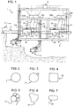
- Number 1 in Figure 1 indicates as a whole a vehicle for burying continuous elongated members in the bed 2 of a body of water 3.
- body of water is intended to mean any stretch of water, such as sea, ocean, lake, etc.
- bed is intended to mean the concave layer of the earth's crust containing the body of water.
- Vehicle 1 is designed to bury a continuous elongated member 4 - in the example shown, an underwater pipeline - extending along a given path P on bed 2, and laid beforehand on bed 2 by a known laying vessel (not shown).
- Vehicle 1 is controlled by a support vessel (not shown), and comprises a frame 5; two tools 6 - in the example shown, cutters - fitted to frame 5; two gripping units 7A, 7B fitted to frame 5; and a control unit 8.
- Continuous elongated member 4 actually guides and anchors vehicle 1, which, as it advances, cuts into a layer of bed 2 directly beneath continuous elongated member 4, to sink continuous elongated member 4 into bed 2 of body of water 3.
- Gripping units 7A, 7B comprise respective grippers 9A, 9B; and respective drives 10A, 10B for selectively connecting grippers 9A, 9B integral with continuous elongated member 4.
- gripping units 7A, 7B serve to advance vehicle 1, which accordingly comprises two guides 11A, 11B and two further drives 12A, 12B; and grippers 9A, 9B are mounted to run along respective guides 11A, 11B, and, in the example shown, comprise respective carriages 13A, 13B.
- Guides 11A, 11B are fitted to frame 5, are aligned with one another, and, in use, are substantially parallel to path P.
- Each drive 10A, 10B comprises at least one valve 14, and at least one hose 15 (only one shown) extending between valve 14 and gripper 9A, 9B to control a gas - in the example shown, compressed air.
- Valve 14 is in turn supplied by a compressor (not shown) on the support vessel (not shown).
- Each drive 12A, 12B comprises two double-acting hydraulic cylinders 16 (only one shown in Figure 1 ) on opposite sides of respective gripper 9A, 9B; a valve 17 for controlling hydraulic cylinders 16; and hoses 18 extending between valve 17 and hydraulic cylinders 16.
- Each hydraulic cylinder 16 is connected to frame 5 and to respective gripper 9A, 9B to move with respect to frame 5.
- Each drive 12A, 12B is connected to a hydraulic pump (not shown) mounted on frame 5 or the supporting vessel (not shown). And drives 12A, 12B serve to move respective grippers 9A, 9B selectively between two given stops, in a direction D1 or a direction D2 opposite direction D1.
- Control unit 8 is supplied with control signals, by which to control operation of valves 14 and 17 and move vehicle 1 forward.
- control unit 8 controls drives 10A, 10B, 12A, 12B to : clamp gripper 9A onto continuous elongated member 4; release gripper 9B from continuous elongated member 4; move gripper 9A in direction D2, with gripper 9A clamped to continuous elongated member 4, and gripper 9B released from continuous elongated member 4; and, at the same time, move gripper 9B in direction D1.
- Vehicle 1 thus moves one step forward in direction D1, by an amount substantially equal to the movement of gripper 9A with respect to frame 5, while gripper 9B is positioned ready to make the next step forward of vehicle 1, by repeating the above operations with grippers 9A and 9B inverted.
- the vehicle is equipped with only one gripper, which means each forward step is followed by a pause to restore the gripper to the start position for the next step.
- the vehicle comprises a number of grippers to achieve a greater contact surface area.
- continuous elongated member 4 has a circular cross section, as shown in Figure 2 , though vehicle 1 is designed to bury continuous elongated members of any cross sectional shape.
- Figure 3 shows the cross section of a continuous elongated member 19 comprising two joined pipes with circular cross sections of different diameters.
- Figure 4 shows a continuous elongated member 20 with a substantially square cross section.
- Figure 5 shows a continuous elongated member 21 comprising a bundle of cables tied with straps F.
- Figure 6 shows a continuous elongated member 22 defined by a cable with an irregular cross section.
- Figure 7 shows a continuous elongated member 23 defined by a cable with a depressed cross section.
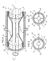
- gripper 9A (and likewise gripper 9B) comprises a tubular structure 24 extending along an axis A; two inflatable bags 25 inside tubular structure 24; two attachments 26 for hoses 15 ( Figure 1 ); and fasteners 27 for securing inflatable bags 25 to tubular structure 24.
- tubular structure 24 is preferably made of metal, has a circular cross section, and is longer than its diameter.
- tubular structure 24 comprises two semicylindrical shells 28, which are hinged to each other by a hinge 29, are fastened shut by fasteners 30, and are releasable to fit gripper 9A about any point along continuous elongated member 4.
- Each bag 25 extends substantially the whole length of tubular structure 24 ( Figure 8 ) and about a cylindrical sector substantially equal in size to a respective shell 28 ( Figure 9 ). In fact, as shown in Figure 9 , inflatable bags 25 are complementary.
- each bag 25 is made from a tubular sheet of flexible, elastic polymer material, having an inner face 31 glued at the ends to seal the tubular sheet into a bag; and an outer face 32, which partly contacts the inner face of the tubular structure, and is designed to partly contact continuous elongated member 4.
- gripper 9A is obvious from the above description of vehicle 1 ( Figure 1 ), it being understood, however, that the gripper also applies to other uses in other technical fields.
- Inflatable bags 25 are pressed selectively against continuous elongated member 4 to clamp gripper 9A to continuous elongated member 4, to enable handling of continuous elongated member 4 by gripper 9A, and to maximize the contact surface area of each inflatable bag 25 without damaging continuous elongated member 4.
- Number 33 in Figure 10 indicates a gripper, which differs from gripper 9A ( Figures 8 and 9 ) by comprising four, as opposed to two, inflatable bags 35, and by each inflatable bag 35 extending circumferentially about a substantially 90°, as opposed to 180°, angle.
- the contact surfaces of the larger number of inflatable bags 35 adapt more readily to irregularly shaped continuous elongated members, so less strain is placed on the deformability of the flexible, elastic sheets.
- Grippers 9A (9B) and 33 according to the present invention may obviously be used in applications other than the one described in connection with vehicle 1 in Figure 1 , but still involving the manipulation of continuous elongated members.
Landscapes
- Engineering & Computer Science (AREA)
- General Engineering & Computer Science (AREA)
- Mechanical Engineering (AREA)
- Mining & Mineral Resources (AREA)
- Civil Engineering (AREA)
- Structural Engineering (AREA)
- Supports For Pipes And Cables (AREA)
- Manipulator (AREA)
- Polarising Elements (AREA)
- Shaping By String And By Release Of Stress In Plastics And The Like (AREA)
- Liquid Crystal (AREA)
- Automatic Assembly (AREA)
Claims (9)
- Dispositif de préhension pour saisir sélectivement des éléments continus de forme allongée, le dispositif de préhension (9A ; 9B ; 33) comprenant une structure de support tubulaire (24) s'étendant le long d'un axe donné (A) et étant conçue pour entourer un élément continu de forme allongée (4, 19, 20, 21, 22, 23) ; au moins deux sacs gonflables (25 ; 35) qui sont fixés à l'intérieur de la structure tubulaire (24) sur la structure tubulaire (24), ayant la forme de secteurs cylindriques complémentaires, étant allongée et s'étendant principalement parallèlement à l'axe (A) ; et deux fixations (26) pour des tuyaux (15) pour gonfler sélectivement les sacs gonflables (25 ; 35), le dispositif de préhension étant caractérisé en ce que les au moins deux sacs gonflables (25 ; 35) sont réalisés à partir d'une feuille tubulaire de matériau polymère flexible élastique, ayant une face interne (31) collée aux extrémités afin de fermer hermétiquement la feuille tubulaire en un sac.
- Dispositif de préhension selon la revendication 1, dans lequel les sacs gonflables (25 ; 35) s'étendent sensiblement sur toute la longueur de la structure tubulaire (24), afin de recouvrir la face interne de la structure tubulaire (24).
- Dispositif de préhension selon l'une quelconque des revendications précédentes, dans lequel chaque sac gonflable (25 ; 35) est fixé sur les extrémités opposées de la structure tubulaire (24), de préférence au moyen de fixations (27).
- Dispositif de préhension selon l'une quelconque des revendications précédentes, dans lequel chaque sac gonflable (25 ; 35) est réalisé à partir d'une feuille tubulaire.
- Dispositif de préhension selon la revendication 4, dans lequel chaque feuille est réalisée à partir de PVC, de préférence avec des raidisseurs transversaux en polyuréthane.
- Dispositif de préhension selon l'une quelconque des revendications précédentes, dans lequel la structure tubulaire (24) comprend des coques (28) sélectivement détachables pour monter le dispositif de préhension (9A ; 9B, 33) autour de l'élément continu de forme allongée (4, 19, 20, 21, 22, 23) ; au moins un sac gonflable (25 ; 35) qui est supporté par une coque (28) respective.
- Dispositif de préhension selon l'une quelconque des revendications précédentes, et comprenant un certain nombre de sacs gonflables (35).
- Véhicule mobile le long d'un élément continu de forme allongée, en particulier pour enfoncer un élément continu de forme allongée (4, 19, 20, 21, 22, 23) dans le lit (2) d'un corps d'eau (3) ; l'élément continu de forme allongée s'étendant le long d'une trajectoire donnée (P) sur le lit (2) ; et le véhicule (1) comprend :- un châssis (5) ;- au moins un dispositif de préhension (9A ; 9A, 9B ; 33) selon au moins l'une des revendications précédentes ;- au moins un dispositif d'entraînement (10A ; 10A, 10B) pour serrer sélectivement le dispositif de préhension (9A ; 9A, 9B ; 33) sur l'élément continu de forme allongée (4, 19, 20, 21, 22, 23) ;- un dispositif d'entraînement supplémentaire (12A ; 12A, 12B) pour déplacer le dispositif de préhension (9A ; 9A, 9B ; 33) selon un mouvement de va-et-vient par rapport au châssis (5) dans deux directions opposées (D1, D2) sensiblement parallèles à l'axe donné (A) ; et une unité de commande (8) pour commander le dispositif d'entraînement (10A ; 10A, 10B) et le dispositif d'entraînement supplémentaire (12A ; 12A, 12B), afin de coordonner le serrage, la libération et le mouvement du dispositif de préhension (9A ; 9A, 9B ; 33) afin de faire avancer le véhicule (1) vers l'avant par paliers.
- Procédé pour faire avancer un véhicule dans une première direction (D1) le long d'un élément continu de forme allongée (4, 19, 20, 21, 22, 23), en particulier un élément continu de forme allongée (4, 19, 20, 21, 22, 23) s'étendant le long d'une trajectoire donnée (P) sur le lit (2) d'un corps d'eau (3) ; le procédé comprenant les étapes consistant à :a) serrer l'élément continu allongé au moyen d'un dispositif de préhension (9A ; 9A, 9B ; 33) monté sur le châssis (5) du véhicule (1), et qui comprend une structure de support tubulaire (24) s'étendant le long d'un axe donné (A) et conçu pour entourer l'élément continu de forme allongée (4, 19, 20, 21, 22, 23) ;b) déplacer le dispositif de préhension (9A ; 9A, 9B ; 33) par rapport au châssis (5), dans une seconde direction (D2) opposée à la première direction (D1) parallèle à la trajectoire (P) et alors que le dispositif de préhension (9A, 9A, 9B ; 33) est serré sur l'élément continu de forme allongée (4, 19, 20, 21, 22, 23), afin de faire avancer le châssis (5), par rapport à l'élément continu de forme allongée (4, 19, 20, 21, 22, 23), le long de la trajectoire donnée (P) ;c) libérer le dispositif de préhension (9A ; 9A, 9B ; 33) de l'élément continu de forme allongée (4, 19, 20, 21, 22, 23) ;d) déplacer le dispositif de préhension (9A ; 9A, 9B ; 33) par rapport au châssis (5) et à l'élément continu de forme allongée (4, 19, 20, 21, 22, 23), dans la première direction (D1), alors que le dispositif de préhension (9A ; 9A, 9B ; 33) est libéré de l'élément continu de forme allongée (4, 19, 20, 21, 22, 23) ; ete) répéter les étapes a) à d) afin de déplacer le véhicule (1) par paliers le long de l'élément continu de forme allongée (4, 19, 20, 21, 22, 23) ; le procédé étant caractérisé en ce que le dispositif de préhension (9A ; 9A, 9B ; 33) comprend au moins deux sacs gonflables (25 ; 35) qui sont fixés à l'intérieur de la structure tubulaire (24) et sur la structure tubulaire (24), ayant la forme de secteurs cylindriques complémentaires, étant allongée et s'étendant principalement parallèlement à l'axe (A) ; et deux fixations (26) pour tuyaux (15) pour gonfler sélectivement les sacs gonflables (25 ; 35) ; dans lequel les au moins deux sacs gonflables (25 ; 35) sont réalisés à partir d'une feuille tubulaire de matériau polymère flexible souple, ayant une face interne (31) collée aux extrémités pour fermer hermétiquement la feuille tubulaire en un sac.
Applications Claiming Priority (2)
| Application Number | Priority Date | Filing Date | Title |
|---|---|---|---|
| IT001702A ITMI20091702A1 (it) | 2009-10-05 | 2009-10-05 | Organo di presa per elementi allungati e continui, veicolo mobile lungo un elemento allungato e continuo, e metodo di avanzamento del veicolo |
| PCT/IB2010/002513 WO2011042790A1 (fr) | 2009-10-05 | 2010-10-05 | Dispositif de préhension pour éléments continus de forme allongée, véhicule mobile le long d'un élément continu de forme allongée, et procédé de déplacement vers l'avant du véhicule |
Publications (2)
| Publication Number | Publication Date |
|---|---|
| EP2486314A1 EP2486314A1 (fr) | 2012-08-15 |
| EP2486314B1 true EP2486314B1 (fr) | 2016-04-13 |
Family
ID=42229206
Family Applications (1)
| Application Number | Title | Priority Date | Filing Date |
|---|---|---|---|
| EP10782370.0A Not-in-force EP2486314B1 (fr) | 2009-10-05 | 2010-10-05 | Dispositif de préhension pour éléments continus de forme allongée, véhicule mobile le long d'un élément continu de forme allongée, et procédé de déplacement vers l'avant du véhicule |
Country Status (5)
| Country | Link |
|---|---|
| US (1) | US9140382B2 (fr) |
| EP (1) | EP2486314B1 (fr) |
| EA (1) | EA022151B1 (fr) |
| IT (1) | ITMI20091702A1 (fr) |
| WO (1) | WO2011042790A1 (fr) |
Families Citing this family (2)
| Publication number | Priority date | Publication date | Assignee | Title |
|---|---|---|---|---|
| WO2017185025A1 (fr) | 2016-04-21 | 2017-10-26 | Bisso Marine, LLC | Appareil et procédé d'enfouissement de pipeline sous-marin |
| US11555558B2 (en) * | 2021-04-23 | 2023-01-17 | C-Dive, LLC | Seafloor pipeline removal system and method |
Citations (1)
| Publication number | Priority date | Publication date | Assignee | Title |
|---|---|---|---|---|
| US4989909A (en) * | 1989-08-17 | 1991-02-05 | Franks Casing Crew And Rental Tools, Inc. | Friction grip for tubular goods |
Family Cites Families (19)
| Publication number | Priority date | Publication date | Assignee | Title |
|---|---|---|---|---|
| US2816575A (en) * | 1953-05-11 | 1957-12-17 | William S Stokes | Apparatus for laying a pipe line under a right-of-way |
| US3038732A (en) * | 1958-04-07 | 1962-06-12 | Texas Pipe Line Company | Inflatable seal bushing for pipeline casing |
| US3023995A (en) * | 1958-07-21 | 1962-03-06 | William C N Hopkins | Sealing and coupling structures |
| NL6814678A (fr) * | 1968-10-14 | 1970-04-16 | ||
| US3734138A (en) * | 1971-03-26 | 1973-05-22 | B Brown | Oil or like transportation system and pipeline support |
| IT999262B (it) * | 1973-11-07 | 1976-02-20 | S S O S Spa | Draga subacquea per l interramento di tubi |
| US4149326A (en) * | 1975-02-11 | 1979-04-17 | Saipem S.P.A. | Machine for digging a trench beneath a submerged pipeline |
| US4274760A (en) * | 1977-08-31 | 1981-06-23 | Norman Robert M | Self-propelled underwater trenching apparatus and method |
| MX147110A (es) * | 1978-03-22 | 1982-10-06 | Epi Pneuma Syst | Equipo para la instalacion subacuatica de tuberias |
| DK191180A (da) * | 1979-05-23 | 1980-11-24 | Coyne & Bellier | Fremgangsmaade og arramgement til forankring af ledninger f eks pipe-line paa havbunden |
| US4516880A (en) * | 1982-04-19 | 1985-05-14 | Martin Charles F | Underwater trenching apparatus |
| US4586850A (en) * | 1983-07-12 | 1986-05-06 | Norman Robert M | Underwater trenching system |
| US5136969A (en) * | 1991-01-25 | 1992-08-11 | Cups, Inc. | Modularized machine for reconditioning pipelines |
| US6022173A (en) | 1994-01-13 | 2000-02-08 | Saxon; Saint E. | Underwater trenching system |
| NL9400517A (nl) * | 1994-03-31 | 1995-11-01 | Allseas Eng Bv | Werkwijze en inrichting voor het leggen van een pijpleiding op een onder water gelegen bodem. |
| US6273642B1 (en) * | 1999-07-21 | 2001-08-14 | Richard A. Anderson | Buoyant propulsion underwater trenching apparatus |
| EG23118A (en) | 2000-06-05 | 2004-04-28 | Stolt Offshore Ltd | Pipe handling apparatus |
| US6705029B2 (en) * | 2002-03-21 | 2004-03-16 | Richard A. Anderson | Trenching machine |
| GB0708206D0 (en) * | 2007-04-27 | 2007-06-06 | Internat Pipeline Products Ltd | Improvements in and relating to connection devices |
-
2009
- 2009-10-05 IT IT001702A patent/ITMI20091702A1/it unknown
-
2010
- 2010-10-05 US US13/500,235 patent/US9140382B2/en not_active Expired - Fee Related
- 2010-10-05 EA EA201270518A patent/EA022151B1/ru not_active IP Right Cessation
- 2010-10-05 EP EP10782370.0A patent/EP2486314B1/fr not_active Not-in-force
- 2010-10-05 WO PCT/IB2010/002513 patent/WO2011042790A1/fr not_active Ceased
Patent Citations (1)
| Publication number | Priority date | Publication date | Assignee | Title |
|---|---|---|---|---|
| US4989909A (en) * | 1989-08-17 | 1991-02-05 | Franks Casing Crew And Rental Tools, Inc. | Friction grip for tubular goods |
Also Published As
| Publication number | Publication date |
|---|---|
| US20120312220A1 (en) | 2012-12-13 |
| WO2011042790A1 (fr) | 2011-04-14 |
| US9140382B2 (en) | 2015-09-22 |
| EP2486314A1 (fr) | 2012-08-15 |
| ITMI20091702A1 (it) | 2011-04-06 |
| EA022151B1 (ru) | 2015-11-30 |
| EA201270518A1 (ru) | 2012-11-30 |
Similar Documents
| Publication | Publication Date | Title |
|---|---|---|
| EP2430346B1 (fr) | Procédé pour raccorder deux tronçons d'un pipeline sous-marin posé sur le fond de la mer pour transporter des fluides et/ou de gaz | |
| US9004818B2 (en) | System, method and apparatus for subsea installation of buoyancy modules | |
| US9126276B2 (en) | Apparatus and method for cutting tubular parts subsea | |
| US7455478B2 (en) | Method for cutting and removing underwater pipelines and apparatus for implementing the same | |
| DK2691683T3 (en) | AUTOMATICALLY DEFENDING STOPPING PIPELINE INSULATION TOOL | |
| WO2007032842A3 (fr) | Système utilisant un conduit flexible à caténaire permettant de transférer un fluide cryogénique | |
| EP2547937A1 (fr) | Appareil sous-marin et procédé de fonctionnement | |
| EP2486314B1 (fr) | Dispositif de préhension pour éléments continus de forme allongée, véhicule mobile le long d'un élément continu de forme allongée, et procédé de déplacement vers l'avant du véhicule | |
| EP3256764B1 (fr) | Dispositif, système et procédé de liaison pour relier deux sections de canalisation alignées et se faisant face | |
| AU2012230364B2 (en) | A/R method and apparatus therefor | |
| EP4222399B1 (fr) | Dispositif manipulateur servant à appliquer des modules autour d'une canalisation, navire de pose comprenant ledit dispositif et procédé d'exploitation dudit navire | |
| EP3215775B1 (fr) | Dispositif de support, navire câblier, et procédé de lancement permettant de poser un pipeline sur le lit d'un plan d'eau | |
| CN222944597U (zh) | 水下切割设备 | |
| EP0963798A1 (fr) | Machine à cintrer les tubes apte à fonctionner au fond de la mer | |
| DK2459918T3 (en) | System, method and apparatus for underwater attachment of buoyancy modules | |
| GB2535195A (en) | Pipeline tensioning apparatus and method |
Legal Events
| Date | Code | Title | Description |
|---|---|---|---|
| PUAI | Public reference made under article 153(3) epc to a published international application that has entered the european phase |
Free format text: ORIGINAL CODE: 0009012 |
|
| 17P | Request for examination filed |
Effective date: 20120430 |
|
| AK | Designated contracting states |
Kind code of ref document: A1 Designated state(s): AL AT BE BG CH CY CZ DE DK EE ES FI FR GB GR HR HU IE IS IT LI LT LU LV MC MK MT NL NO PL PT RO RS SE SI SK SM TR |
|
| DAX | Request for extension of the european patent (deleted) | ||
| REG | Reference to a national code |
Ref country code: DE Ref legal event code: R079 Ref document number: 602010032286 Country of ref document: DE Free format text: PREVIOUS MAIN CLASS: F16L0001160000 Ipc: E02F0005100000 |
|
| RIC1 | Information provided on ipc code assigned before grant |
Ipc: E02F 5/10 20060101AFI20130328BHEP Ipc: F16L 1/16 20060101ALI20130328BHEP |
|
| 17Q | First examination report despatched |
Effective date: 20130510 |
|
| GRAP | Despatch of communication of intention to grant a patent |
Free format text: ORIGINAL CODE: EPIDOSNIGR1 |
|
| INTG | Intention to grant announced |
Effective date: 20151009 |
|
| GRAS | Grant fee paid |
Free format text: ORIGINAL CODE: EPIDOSNIGR3 |
|
| GRAA | (expected) grant |
Free format text: ORIGINAL CODE: 0009210 |
|
| AK | Designated contracting states |
Kind code of ref document: B1 Designated state(s): AL AT BE BG CH CY CZ DE DK EE ES FI FR GB GR HR HU IE IS IT LI LT LU LV MC MK MT NL NO PL PT RO RS SE SI SK SM TR |
|
| REG | Reference to a national code |
Ref country code: GB Ref legal event code: FG4D |
|
| REG | Reference to a national code |
Ref country code: AT Ref legal event code: REF Ref document number: 790327 Country of ref document: AT Kind code of ref document: T Effective date: 20160415 Ref country code: CH Ref legal event code: EP |
|
| REG | Reference to a national code |
Ref country code: IE Ref legal event code: FG4D |
|
| REG | Reference to a national code |
Ref country code: DE Ref legal event code: R096 Ref document number: 602010032286 Country of ref document: DE |
|
| REG | Reference to a national code |
Ref country code: NL Ref legal event code: FP |
|
| REG | Reference to a national code |
Ref country code: LT Ref legal event code: MG4D |
|
| REG | Reference to a national code |
Ref country code: AT Ref legal event code: MK05 Ref document number: 790327 Country of ref document: AT Kind code of ref document: T Effective date: 20160413 |
|
| REG | Reference to a national code |
Ref country code: FR Ref legal event code: PLFP Year of fee payment: 7 |
|
| PG25 | Lapsed in a contracting state [announced via postgrant information from national office to epo] |
Ref country code: FI Free format text: LAPSE BECAUSE OF FAILURE TO SUBMIT A TRANSLATION OF THE DESCRIPTION OR TO PAY THE FEE WITHIN THE PRESCRIBED TIME-LIMIT Effective date: 20160413 Ref country code: NO Free format text: LAPSE BECAUSE OF FAILURE TO SUBMIT A TRANSLATION OF THE DESCRIPTION OR TO PAY THE FEE WITHIN THE PRESCRIBED TIME-LIMIT Effective date: 20160713 Ref country code: PL Free format text: LAPSE BECAUSE OF FAILURE TO SUBMIT A TRANSLATION OF THE DESCRIPTION OR TO PAY THE FEE WITHIN THE PRESCRIBED TIME-LIMIT Effective date: 20160413 Ref country code: LT Free format text: LAPSE BECAUSE OF FAILURE TO SUBMIT A TRANSLATION OF THE DESCRIPTION OR TO PAY THE FEE WITHIN THE PRESCRIBED TIME-LIMIT Effective date: 20160413 |
|
| PG25 | Lapsed in a contracting state [announced via postgrant information from national office to epo] |
Ref country code: RS Free format text: LAPSE BECAUSE OF FAILURE TO SUBMIT A TRANSLATION OF THE DESCRIPTION OR TO PAY THE FEE WITHIN THE PRESCRIBED TIME-LIMIT Effective date: 20160413 Ref country code: ES Free format text: LAPSE BECAUSE OF FAILURE TO SUBMIT A TRANSLATION OF THE DESCRIPTION OR TO PAY THE FEE WITHIN THE PRESCRIBED TIME-LIMIT Effective date: 20160413 Ref country code: GR Free format text: LAPSE BECAUSE OF FAILURE TO SUBMIT A TRANSLATION OF THE DESCRIPTION OR TO PAY THE FEE WITHIN THE PRESCRIBED TIME-LIMIT Effective date: 20160714 Ref country code: HR Free format text: LAPSE BECAUSE OF FAILURE TO SUBMIT A TRANSLATION OF THE DESCRIPTION OR TO PAY THE FEE WITHIN THE PRESCRIBED TIME-LIMIT Effective date: 20160413 Ref country code: AT Free format text: LAPSE BECAUSE OF FAILURE TO SUBMIT A TRANSLATION OF THE DESCRIPTION OR TO PAY THE FEE WITHIN THE PRESCRIBED TIME-LIMIT Effective date: 20160413 Ref country code: LV Free format text: LAPSE BECAUSE OF FAILURE TO SUBMIT A TRANSLATION OF THE DESCRIPTION OR TO PAY THE FEE WITHIN THE PRESCRIBED TIME-LIMIT Effective date: 20160413 Ref country code: PT Free format text: LAPSE BECAUSE OF FAILURE TO SUBMIT A TRANSLATION OF THE DESCRIPTION OR TO PAY THE FEE WITHIN THE PRESCRIBED TIME-LIMIT Effective date: 20160816 Ref country code: SE Free format text: LAPSE BECAUSE OF FAILURE TO SUBMIT A TRANSLATION OF THE DESCRIPTION OR TO PAY THE FEE WITHIN THE PRESCRIBED TIME-LIMIT Effective date: 20160413 |
|
| PG25 | Lapsed in a contracting state [announced via postgrant information from national office to epo] |
Ref country code: BE Free format text: LAPSE BECAUSE OF FAILURE TO SUBMIT A TRANSLATION OF THE DESCRIPTION OR TO PAY THE FEE WITHIN THE PRESCRIBED TIME-LIMIT Effective date: 20160413 |
|
| REG | Reference to a national code |
Ref country code: DE Ref legal event code: R097 Ref document number: 602010032286 Country of ref document: DE |
|
| PG25 | Lapsed in a contracting state [announced via postgrant information from national office to epo] |
Ref country code: CZ Free format text: LAPSE BECAUSE OF FAILURE TO SUBMIT A TRANSLATION OF THE DESCRIPTION OR TO PAY THE FEE WITHIN THE PRESCRIBED TIME-LIMIT Effective date: 20160413 Ref country code: EE Free format text: LAPSE BECAUSE OF FAILURE TO SUBMIT A TRANSLATION OF THE DESCRIPTION OR TO PAY THE FEE WITHIN THE PRESCRIBED TIME-LIMIT Effective date: 20160413 Ref country code: DK Free format text: LAPSE BECAUSE OF FAILURE TO SUBMIT A TRANSLATION OF THE DESCRIPTION OR TO PAY THE FEE WITHIN THE PRESCRIBED TIME-LIMIT Effective date: 20160413 Ref country code: RO Free format text: LAPSE BECAUSE OF FAILURE TO SUBMIT A TRANSLATION OF THE DESCRIPTION OR TO PAY THE FEE WITHIN THE PRESCRIBED TIME-LIMIT Effective date: 20160413 Ref country code: SK Free format text: LAPSE BECAUSE OF FAILURE TO SUBMIT A TRANSLATION OF THE DESCRIPTION OR TO PAY THE FEE WITHIN THE PRESCRIBED TIME-LIMIT Effective date: 20160413 |
|
| PLBE | No opposition filed within time limit |
Free format text: ORIGINAL CODE: 0009261 |
|
| STAA | Information on the status of an ep patent application or granted ep patent |
Free format text: STATUS: NO OPPOSITION FILED WITHIN TIME LIMIT |
|
| PG25 | Lapsed in a contracting state [announced via postgrant information from national office to epo] |
Ref country code: SM Free format text: LAPSE BECAUSE OF FAILURE TO SUBMIT A TRANSLATION OF THE DESCRIPTION OR TO PAY THE FEE WITHIN THE PRESCRIBED TIME-LIMIT Effective date: 20160413 |
|
| 26N | No opposition filed |
Effective date: 20170116 |
|
| REG | Reference to a national code |
Ref country code: DE Ref legal event code: R119 Ref document number: 602010032286 Country of ref document: DE |
|
| PG25 | Lapsed in a contracting state [announced via postgrant information from national office to epo] |
Ref country code: SI Free format text: LAPSE BECAUSE OF FAILURE TO SUBMIT A TRANSLATION OF THE DESCRIPTION OR TO PAY THE FEE WITHIN THE PRESCRIBED TIME-LIMIT Effective date: 20160413 |
|
| REG | Reference to a national code |
Ref country code: CH Ref legal event code: PL |
|
| REG | Reference to a national code |
Ref country code: IE Ref legal event code: MM4A |
|
| PG25 | Lapsed in a contracting state [announced via postgrant information from national office to epo] |
Ref country code: CH Free format text: LAPSE BECAUSE OF NON-PAYMENT OF DUE FEES Effective date: 20161031 Ref country code: DE Free format text: LAPSE BECAUSE OF NON-PAYMENT OF DUE FEES Effective date: 20170503 Ref country code: LI Free format text: LAPSE BECAUSE OF NON-PAYMENT OF DUE FEES Effective date: 20161031 |
|
| PG25 | Lapsed in a contracting state [announced via postgrant information from national office to epo] |
Ref country code: LU Free format text: LAPSE BECAUSE OF NON-PAYMENT OF DUE FEES Effective date: 20161005 |
|
| REG | Reference to a national code |
Ref country code: FR Ref legal event code: PLFP Year of fee payment: 8 |
|
| PG25 | Lapsed in a contracting state [announced via postgrant information from national office to epo] |
Ref country code: IE Free format text: LAPSE BECAUSE OF NON-PAYMENT OF DUE FEES Effective date: 20161005 |
|
| PG25 | Lapsed in a contracting state [announced via postgrant information from national office to epo] |
Ref country code: HU Free format text: LAPSE BECAUSE OF FAILURE TO SUBMIT A TRANSLATION OF THE DESCRIPTION OR TO PAY THE FEE WITHIN THE PRESCRIBED TIME-LIMIT; INVALID AB INITIO Effective date: 20101005 Ref country code: CY Free format text: LAPSE BECAUSE OF FAILURE TO SUBMIT A TRANSLATION OF THE DESCRIPTION OR TO PAY THE FEE WITHIN THE PRESCRIBED TIME-LIMIT Effective date: 20160413 |
|
| PG25 | Lapsed in a contracting state [announced via postgrant information from national office to epo] |
Ref country code: TR Free format text: LAPSE BECAUSE OF FAILURE TO SUBMIT A TRANSLATION OF THE DESCRIPTION OR TO PAY THE FEE WITHIN THE PRESCRIBED TIME-LIMIT Effective date: 20160413 Ref country code: MC Free format text: LAPSE BECAUSE OF FAILURE TO SUBMIT A TRANSLATION OF THE DESCRIPTION OR TO PAY THE FEE WITHIN THE PRESCRIBED TIME-LIMIT Effective date: 20160413 Ref country code: MK Free format text: LAPSE BECAUSE OF FAILURE TO SUBMIT A TRANSLATION OF THE DESCRIPTION OR TO PAY THE FEE WITHIN THE PRESCRIBED TIME-LIMIT Effective date: 20160413 Ref country code: IS Free format text: LAPSE BECAUSE OF FAILURE TO SUBMIT A TRANSLATION OF THE DESCRIPTION OR TO PAY THE FEE WITHIN THE PRESCRIBED TIME-LIMIT Effective date: 20160413 Ref country code: MT Free format text: LAPSE BECAUSE OF NON-PAYMENT OF DUE FEES Effective date: 20161031 |
|
| PG25 | Lapsed in a contracting state [announced via postgrant information from national office to epo] |
Ref country code: BG Free format text: LAPSE BECAUSE OF FAILURE TO SUBMIT A TRANSLATION OF THE DESCRIPTION OR TO PAY THE FEE WITHIN THE PRESCRIBED TIME-LIMIT Effective date: 20160413 |
|
| REG | Reference to a national code |
Ref country code: FR Ref legal event code: PLFP Year of fee payment: 9 |
|
| PG25 | Lapsed in a contracting state [announced via postgrant information from national office to epo] |
Ref country code: AL Free format text: LAPSE BECAUSE OF FAILURE TO SUBMIT A TRANSLATION OF THE DESCRIPTION OR TO PAY THE FEE WITHIN THE PRESCRIBED TIME-LIMIT Effective date: 20160413 |
|
| PGFP | Annual fee paid to national office [announced via postgrant information from national office to epo] |
Ref country code: NL Payment date: 20221025 Year of fee payment: 13 Ref country code: FR Payment date: 20221024 Year of fee payment: 13 |
|
| PGFP | Annual fee paid to national office [announced via postgrant information from national office to epo] |
Ref country code: IT Payment date: 20221020 Year of fee payment: 13 Ref country code: GB Payment date: 20221018 Year of fee payment: 13 |
|
| REG | Reference to a national code |
Ref country code: NL Ref legal event code: MM Effective date: 20231101 |
|
| GBPC | Gb: european patent ceased through non-payment of renewal fee |
Effective date: 20231005 |
|
| PG25 | Lapsed in a contracting state [announced via postgrant information from national office to epo] |
Ref country code: GB Free format text: LAPSE BECAUSE OF NON-PAYMENT OF DUE FEES Effective date: 20231005 |
|
| PG25 | Lapsed in a contracting state [announced via postgrant information from national office to epo] |
Ref country code: NL Free format text: LAPSE BECAUSE OF NON-PAYMENT OF DUE FEES Effective date: 20231101 |
|
| PG25 | Lapsed in a contracting state [announced via postgrant information from national office to epo] |
Ref country code: NL Free format text: LAPSE BECAUSE OF NON-PAYMENT OF DUE FEES Effective date: 20231101 Ref country code: GB Free format text: LAPSE BECAUSE OF NON-PAYMENT OF DUE FEES Effective date: 20231005 Ref country code: FR Free format text: LAPSE BECAUSE OF NON-PAYMENT OF DUE FEES Effective date: 20231031 |
|
| PG25 | Lapsed in a contracting state [announced via postgrant information from national office to epo] |
Ref country code: IT Free format text: LAPSE BECAUSE OF NON-PAYMENT OF DUE FEES Effective date: 20231005 |
|
| PG25 | Lapsed in a contracting state [announced via postgrant information from national office to epo] |
Ref country code: IT Free format text: LAPSE BECAUSE OF NON-PAYMENT OF DUE FEES Effective date: 20231005 |