EP2486839B1 - Lave-vaisselle doté d'un joint de porte - Google Patents
Lave-vaisselle doté d'un joint de porte Download PDFInfo
- Publication number
- EP2486839B1 EP2486839B1 EP12152449.0A EP12152449A EP2486839B1 EP 2486839 B1 EP2486839 B1 EP 2486839B1 EP 12152449 A EP12152449 A EP 12152449A EP 2486839 B1 EP2486839 B1 EP 2486839B1
- Authority
- EP
- European Patent Office
- Prior art keywords
- end portion
- door
- holding portion
- stop surface
- dishwasher according
- Prior art date
- Legal status (The legal status is an assumption and is not a legal conclusion. Google has not performed a legal analysis and makes no representation as to the accuracy of the status listed.)
- Active
Links
Images


Classifications
-
- A—HUMAN NECESSITIES
- A47—FURNITURE; DOMESTIC ARTICLES OR APPLIANCES; COFFEE MILLS; SPICE MILLS; SUCTION CLEANERS IN GENERAL
- A47L—DOMESTIC WASHING OR CLEANING; SUCTION CLEANERS IN GENERAL
- A47L15/00—Washing or rinsing machines for crockery or tableware
- A47L15/42—Details
- A47L15/4251—Details of the casing
- A47L15/4257—Details of the loading door
- A47L15/4263—Door sealing arrangements
-
- A—HUMAN NECESSITIES
- A47—FURNITURE; DOMESTIC ARTICLES OR APPLIANCES; COFFEE MILLS; SPICE MILLS; SUCTION CLEANERS IN GENERAL
- A47L—DOMESTIC WASHING OR CLEANING; SUCTION CLEANERS IN GENERAL
- A47L15/00—Washing or rinsing machines for crockery or tableware
- A47L15/42—Details
- A47L15/4246—Details of the tub
-
- A—HUMAN NECESSITIES
- A47—FURNITURE; DOMESTIC ARTICLES OR APPLIANCES; COFFEE MILLS; SPICE MILLS; SUCTION CLEANERS IN GENERAL
- A47L—DOMESTIC WASHING OR CLEANING; SUCTION CLEANERS IN GENERAL
- A47L15/00—Washing or rinsing machines for crockery or tableware
- A47L15/42—Details
- A47L15/421—Safety arrangements for preventing water damage
- A47L15/4212—Detection of water leaks; Collection of leaked water, e.g. in the casing
-
- A—HUMAN NECESSITIES
- A47—FURNITURE; DOMESTIC ARTICLES OR APPLIANCES; COFFEE MILLS; SPICE MILLS; SUCTION CLEANERS IN GENERAL
- A47L—DOMESTIC WASHING OR CLEANING; SUCTION CLEANERS IN GENERAL
- A47L2401/00—Automatic detection in controlling methods of washing or rinsing machines for crockery or tableware, e.g. information provided by sensors entered into controlling devices
- A47L2401/09—Water level
-
- A—HUMAN NECESSITIES
- A47—FURNITURE; DOMESTIC ARTICLES OR APPLIANCES; COFFEE MILLS; SPICE MILLS; SUCTION CLEANERS IN GENERAL
- A47L—DOMESTIC WASHING OR CLEANING; SUCTION CLEANERS IN GENERAL
- A47L2501/00—Output in controlling method of washing or rinsing machines for crockery or tableware, i.e. quantities or components controlled, or actions performed by the controlling device executing the controlling method
- A47L2501/26—Indication or alarm to the controlling device or to the user
Definitions
- the invention relates to a dishwasher, in particular a domestic dishwasher, with a washing container for receiving items to be cleaned, which is closed on its front facing a user by a relative to the washing container movably mounted door, wherein at least one door seal for sealing a gap between the lower region the door and the rinsing container is provided, and wherein the door seal is fastened at least on an inner region of the door facing the rinsing container and on an edge region of a bottom region of the rinsing container located in the vicinity of the front side.
- a dishwasher according to the preamble of claim 1 is made DE19933700 A1 known.
- the object of the invention is to propose an improved connection between the door seal and the washing container.
- the said door seal in particular lower door seal, at its end secured to the edge of the washing container has an end portion which is at least partially surrounded by a corresponding holding portion of the edge region, wherein the holding portion has a first stop surface and a second abutment surface respectively in contact with the end portion, and wherein the first abutment surface and the second abutment surface are aligned with respect to the end portion so as to oppose a torque transmitted from the door to the end portion at least when opening the door.
- the holding portion at least partially surrounds the end portion of the door seal, in particular lower door seal, which may be formed, for example, as aligned parallel to the axis of rotation of the door, ensures that the end portion can be reliably held.
- the end portion comprises two sections which are arranged on both sides of the end portion of the door seal.
- the door seal would now endeavored without appropriate countermeasures to rotate due to the torque around a parallel to the contact surface between the door seal and holding portion extending axis of rotation.
- the holding portion according to the present invention has first and second abutment surfaces aligned with respect to the end portion so as to be capable of receiving the aforementioned torque, then it will be forwarded to the holding apparatus without causing disconnection between the holding portion and the door seal to be able to. Rather, results from the said torque, a force which presses the areas of the end portion, which are in contact with the two stop surfaces, even more to these surfaces.
- connection can withstand the torques occurring during opening, so that the gap between the door and the washing container is always reliably sealed.
- the construction according to the invention ensures that the torque exerted on closing the door on this door seal, in particular the lower door seal, counteracts a corresponding counter-torque.
- the door seal is formed as a sealing strip with a longitudinal axis which is parallel to the axis of rotation of the door.
- the sealing strip may in this case have a particularly flexible central region and correspondingly rigid or reinforced end sections, wherein one end section according to the invention with the holding section and the second end section with the door is connected.
- the door seal particularly spans the gap between the lower end portion of the door and the holding portion. If the door is now opened, the second end section of the door seal is moved in a circular path around the axis of rotation with a corresponding position of the axis of rotation of the door.
- this second end section likewise experiences a partial arcuate, in particular circular or elliptical, displacement with respect to the end section, which is connected to the holding section.
- the resulting torque is finally transmitted via the abutment surfaces to the rigidly arranged holding section, so that an undesired release of the connection between the door seal and the holding section can be excluded.
- the end portion engages in a recess of the holding portion.
- the depression which may be channel-shaped, for example, extends over a large part of the width of the dishwasher, in particular between its side walls bounding the washing compartment.
- the end portion may be flange-shaped in this case and may be either rectilinear, bent or kinked (e.g., hook-shaped) with respect to the remainder of the door seal. In the latter case, the end portion can be hung in the recess.
- the recess and the end portion are matched to one another such that the end portion is pressed into the recess, overcoming a certain frictional force, so that in the closed position, in the usually no or only a small torque on the End section acts, a liquid-tight connection between the door seal and rinsing takes place.
- the end portion of the door seal is positively, frictionally, and / or non-positively inserted into the recess of the holding portion of the lower front-side edge portion of the washing compartment.
- the first abutment surface and the second abutment surface are at least partially formed by surfaces which bound the recess.
- no separate stop surfaces are necessary in addition to the well boundary surfaces.
- the connection area between the end region of the door seal and the holding section can thus be realized in a space-saving manner.
- the boundary surfaces are preferably aligned substantially parallel to each other in this variant, so that they can serve the torque absorption and embracing the end portion.
- the holding section has a region with a U-shaped cross section, wherein the first stop surface and the second stop surface are formed by the two inner regions of the legs of the holding section.
- the end portion is non-positively connected to the holding portion, wherein the end portion of the holding portion is preferably held by clamping.
- the end portion is pressed in this case during assembly of the dishwasher between the legs and held by appropriate friction forces in place.
- the resulting holding force is further amplified by the torque occurring, so that especially in this door position, a particularly stable connection between the door seal and the bottom portion of the dishwasher can be ensured.
- the end portion of the first stop surface and the second stop surface of the holding portion is clamped.
- the stop surfaces in addition to the clamping of the end portion also serve to absorb the torque occurring at least during the opening of the door.
- the holding portion or the end portion has a bulge, for example in the form of a thickening of its cross section, which engages in an undercut or recess of the end portion or the holding portion, in particular resulting in a positive connection between the holding portion and end portion.
- a bulge for example in the form of a thickening of its cross section, which engages in an undercut or recess of the end portion or the holding portion, in particular resulting in a positive connection between the holding portion and end portion.
- a portion of the holding portion a W-shaped or E-shaped and a portion of the end portion of the door seal a U-shaped cross-section, wherein the legs of the end portion of each of two legs of the holding portion, preferably by clamping, are embraced ,
- This finally creates a particularly large overlap or contact surface between the holding section and the end section.
- this results in several kinks of both sections, which, if they abut each other, for a high liquid-tightness of the connection of door seal and washing, especially in the closed position of the door and / or in particular in any open position of the door, provide.
- a region of the holding section and / or of the end section in cross-section has a U-shape, a W-shape and / or E-shape, the legs of which are aligned parallel to one another.
- both sections may be configured and matched to one another in such a way that all leg surfaces of the end section are in direct contact with corresponding leg surfaces of the holding section, it is also possible for individual ones of the mentioned surfaces to be arranged at a distance from one another, this distance occurring when a corresponding torque occurs can be reduced by bending the individual legs. By this bending eventually manufacturing tolerances are compensated, so that the result is the necessary connection between the door seal and the holding section.
- a region of the holding portion in cross-section on a U-shape, a W-shape or E-shape the legs each have an upper edge, which are arranged offset from one another with respect to a horizontal plane.
- the upper edge projecting furthest upwards relative to the dishwasher base is arranged closest to the door (in its closed position). This upper edge thus forms an outer end of the washing container.
- the remaining legs each have upper edges which lie below this upper edge. If the end section is then placed on the holding section, the structure formed from the holding section and the end section is bounded on one side by the upper edge of the holding section described above. Since the other legs of the holding portion are arranged lower, finally, the end portion can be slipped over these legs and connected to this, without causing a structure having a height which would exceed the height of the highest upper edge of the holding portion.
- the end portion has a sealing lip, which bears against the holding portion, in particular on an inner surface of the holding portion facing the interior of the washing container.
- This sealing lip further improves the sealing between the holding section and the door seal, wherein the sealing lip for this advantageously extends substantially parallel to the end section of the door seal.
- the sealing lip can be formed integrally with the end portion or the door seal. Conceivable, however, are embodiments in which the sealing lip is present as a separate component, which is connected in accordance with the rest of the door seal.
- the door seal in its closed position, a bias, which exerts a torque on the end portion.
- a force acts on the door seal already in this position, which, however, can also be forwarded via the stop surfaces according to the invention to the holding section.
- the end portion becomes thus pressed in each door position by the torque occurring against the stop surfaces and thus fixed relative to the holding portion.
- the holding portion and the end portion each have a parallel to the axis of rotation of the door extending surface portion, wherein the surface portions are adjacent to each other and arranged in a plane.
- the surface sections serve in this case as the upper edge of the washing in the door direction.
- both elements should abut each other as closely as possible in the area of said surface portions, so that a nearly uniform surface is formed.
- the holding portion has a third abutment surface and a fourth abutment surface, which are in contact with the end portion, wherein the third abutment surface and the fourth abutment surface are also aligned with respect to the end portion such that they, at least when opening the Door, counteract by the door on the end portion transmitted torque.
- the connection between the door seal and container bottom has in this case a particularly high resistance to torques occurring, in particular when closing and / or opening the door on.
- the respective surfaces are preferably arranged substantially parallel to one another and can be located, for example, on the inner legs of a W-shaped holding section.
- each of the stop surfaces associated areas of the end portion are pressed at least during and after opening the door by the torque described in the direction of the stop surfaces, arises at this stage always a particularly strong and liquid-tight connection between the door seal and holding section, so that accidental release of Door seal, especially when the door is open, can almost be excluded.
- the rinsing container preferably comprises a base tray or a rinsing container base made of plastic, which contains the holding portion.
- the holding section and the base pan can be cast in one piece or produced by means of a pressing process, resulting in a low production cost.
- the rinsing container bottom can be placed or applied on top of a base assembly, in particular made of plastic.
- the bottom assembly is used to accommodate components of the dishwasher such. For example, the circulation pump, drain pump, water separator, leveling feet, electronic control / regulating device, etc.
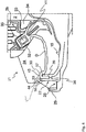
- Dishwasher 1 shown schematically is a domestic dishwasher and has a washing container 2 for receiving items to be cleaned, such as dishes, pots, cutlery, glasses, cooking utensils u. ⁇ ., on.
- the rinsing container 2 has an at least substantially rectangular floor plan with a front side V facing a user in the operating position.
- the washing container 2 can be closed by a door 3, in particular on its front side V.
- This door 3 is in FIG. 1 shown in the closed position and, for example, pivotable about a lower axis of rotation 3a in the direction of the arrow 3d. Another, different from the pivoting opening movement is possible.
- the items to be washed are kept in a lower rack 4 and an upper rack 5 during the wash program.
- the number of crockery baskets 4, 5 may vary depending on the size and type of the dishwasher 1. Also, a so-called cutlery drawer may be additionally provided.
- the crockery baskets 4, 5 are via one or more spray devices, for example in the form of rotatable spray arms 6, 7 and / or individual nozzles 8, with fresh water FW and / or with circulating water, with cleaning agents or cleaning aids, such as rinse aid, is added (so-called rinse S), acted upon.
- the crockery baskets 4, 5 can be displaced forward, for example, on rollers 10, so as to achieve an access position for the user, in which he can load and unload the crockery baskets 4, 5 comfortably.
- the fresh water FW and / or the circulating and with cleaning agents, rinse aids, additives such as softeners, and / or contaminants from the dishes, staggered wash liquor S runs after appropriate distribution in the washing container 2 via a arranged in the bottom portion 15 of the washing container 2 screen unit 11 one of these downstream circulating pump unit 12. From this, the said liquids over at least one in FIG. 1 only schematically illustrated heater 13 to a manifold 14 and from there to the said sprayers 6, 7, 8 passed. For pumping out the liquid from the washing container 2 is finally passed through a pump 9 as wastewater AW from the machine 1.
- the heater 13 may conveniently be housed in the circulation pump unit 12.
- the pivotable door 3 further includes a relative to the bottom portion 15 of the washing compartment 2 vapor-tight and liquid-sealed inner region 3b, which is often referred to as the inner door. This is firmly connected to an adjoining outward outer area 3c, which is often referred to as the outer door.
- the outer area 3c comprises at least one front-side planar panel 16 and two lateral panels 17 so that a U-shaped cross-sectional configuration of the outer door 3c results in a view from below in the lower area of the outer door 3c.
- the front panel 16 may be followed by a furniture panel or other decorative surface forward.
- a base 19 which can accommodate the above-mentioned pumps 9, 12, the heater 13, the manifold 14 and other technical elements and which is supported for example on feet SF against the ground.
- lower door seal D is set in the lower part of the door 3 near the pivot axis 3a with its door-side end at the lower portion 18 of the inner door (a possible fastening solution shows, for example FIG. 4 and will be described below).
- the lower door seal hereinafter referred to as a door seal, D is used essentially for sealing a gap 21 between the lower portion 18 of the door 3 and the washing container 2 and is for this purpose with its container-side end portion 30 at a near the front V located raised and Here, generally designated 20 holding portion 22 of a bottom portion 15 of the washing container 2, the so-called. Container snout, set.
- the lower door transverse seal or door seal D is preferably designed to be uniformly continuous over its course transverse to the dishwasher 1 (i.e., parallel to the axis of rotation 3a of the door 3).
- the washing container 2 also has a stepped structure 23 in the region of the front side V. This includes over its longitudinal course, ie in the transverse direction of the dishwasher 1, two laterally arranged sealing portions 26, which extend beyond the height of the overlapped by the door seal D upper edge of the holding portion 22, and at least one demand overflow area 27 adjacent to the door seal D and part of the holding portion 22 is.
- the sealing regions 26 prevent by their height that liquid which runs over the upper, held on the holding portion 22 edge of the door seal D, can continue to flow to the front side V. Rather, this liquid can only run over the lower-lying demand overflow area 27.
- the raised sealing regions 26 each extend from a right and a left side wall 24, 25 of the washing container 2 and extend from there in the direction of its transverse center.
- the transition from the side walls 24, 25 to the sealing regions 26 is in each case liquid-tight, in particular, as explained below, in one piece.
- the lowered demand overflow area 27 is formed. This is preferably at most as high as the adjacent end of the door seal D, so that there overflowing liquid can be discharged to the front over the demand overflow area 27.
- evenly standing demand overflow area 27 is provided, which is continuous from its beginning in the vicinity of the left side wall 24 beyond the transverse center to its end in the vicinity of the right side wall 25.
- the demand overflow region 27 in the region of the front side V adjoins a drainage channel 28, via which liquid overflowing in this region can be returned to the base 19 via a hose or the like.
- the overflow can be detected, for example, as an error and recorded in a fault memory.
- the gutter 28 is bounded to the front V by a front wall 29 and does not have to extend across the entire width between the side walls 24, 25. Rather, it is sufficient if the drainage channel 28 extends between the sealing regions 26, since no liquid can run over the sealing regions 26. The space in front of the sealing areas 26 can therefore remain free and be used for the placement of hinges or other connections.
- the stepped structure 23 and the gutter 28 are formed integrally with their front wall 29 in one piece and in particular made of plastic.
- the washing container 2 may comprise a floor unit and a hood unit connected thereto, the raised holding portion 22 of the floor unit is assigned and this may consist in particular of plastic. Then, it is possible, as shown in the figures, the bottom unit, and the raised holding portion 22 (with the need-overflow area 27) together with the gutter 28 and the front wall 29 integrally formed.
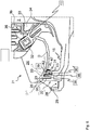
- the door seal D itself can be elastically flexible as an extrusion profile about a rotation axis 3 a movable and is connected via its end portion 30 with the washing compartment 2.
- the end section 30 of the door seal D is at least partially surrounded by a corresponding holding section 22 of the edge region 20.
- the holding portion 22 for this purpose, for example, a grooved or groove-shaped, in particular U-shaped recess 36, the forward by the demand overflow area 27 and the adjacent sealing areas 26 and in the direction of the washing compartment 2 by an inner transverse wall 37th is limited.
- the Spül thereerinnenraum facing leg or the inner transverse wall 37 of the holding portion 22 of the edge portion 20 of the U-shaped, downwardly directed end portion 30 of the lower door seal is slipped over from above.
- the inner surface of the outer, further front of the edge region 20 of the bottom 15 of the washing container 2 arranged leg (transverse wall) 371 serves as a stop surface 38 for the inserted into the groove or groove-shaped recess 36 or inserted end portion 30 of the lower door seal D.
- the aforementioned boundaries also have a first abutment surface 38 and a second abutment surface 39, which in turn are in contact with the end portion 30 of the door seal D. Due to the design of the recess 36, the first abutment surface 38 and the second abutment surface 39 are now aligned with respect to the end portion 30 so that they can counteract a torque transmitted from the door 3 to the end portion 30 when opening the door 3, ie in particular a corresponding counter torque provide for self-securing the lower door seal. The torque exerted on the lower door seal is thus largely compensated by a corresponding counter torque.
- the torque is produced by the fact that the second end section 41 of the door seal D fastened to the door 3 opens around the door 3 when the door 3 is opened lower axis of rotation 3a while looking at FIG. 4 is moved to the top left.
- This torque acts on the end portion 30, finally causes a pressing of the first abutment surface 38 opposite portion of the end portion 30 against the first abutment surface 38 forming the upper left portion of the recess 36.
- the lower right portion of the end portion 30 against the lower right portion pressed the recess 36, which forms the second stop surface 39 in this case.
- the construction according to the invention also causes a corresponding counter-torque, which is directed counter to the torque acting on the lower door transverse seal.
- FIG. 5 shows the embodiment according to FIG. 5 an end portion 30 whose cross section corresponds to a downwardly open "U".
- the end portion 30 is in this case slipped from above over the already known, the Spül electerinnenraum facing transverse wall 37, wherein the left leg of the U-shaped end portion 30 in turn into the recess 36, which has a predetermined transverse gap width (viewed in the depth direction) engages to a torque to be transmitted to the stop surfaces 38, 39 can.
- the transverse wall 37 of the holding portion 22 has a thickening 31 of its cross section, which engages in an undercut of the end portion 30 of the door seal D. Since these teeth can counteract a torque, the stability of the connection between the door seal D and holding portion 22 is further enhanced thereby.
- a toothing 40 may be provided on the door seal D and / or on the holding portion 22 as an additional trigger safety, as shown in the FIGS. 6 and 7 is shown.
- FIG. 8 a further alternative embodiment of the holding portion 22 and the corresponding end portion 30 of the door seal D .
- the holding portion 22 in side view of the washing container inwardly toward the Spül organizationserinnenraum towards a third abutment surface 42 and a spaced apart in the depth direction with a predetermined transverse gap width fourth stop surface 43, which are also in contact with the end portion 30, wherein the third abutment surface 42 and the fourth stop surface 43 are in turn aligned with respect to the end portion 30 such that they counteract a, at least when opening the door 3, transmitted from the door 3 to the end portion 30 torque.
- the holding portion two U-shaped recesses 36, 36 'are provided which extend in the width direction of the washing container over the entire width of the feed opening in the front holding portion 22 of the bottom tray 15 of the washing compartment 2.
- the legs of these two U-shaped depressions 36, 36 'are each arranged one behind the other with a depth spacing.
- the leg or the transverse wall 37 forms a common leg for both U-shaped recess grooves 36, 36 '.
- a sealing lip 47 may be provided, which abuts against the holding portion 22, in particular on the inner surface of the washing container 2 facing inner surface of the holding portion 22 and also prevents penetration of liquid into the area between the door seal D and holding portion 22.
- the holding portion 22 at least in the area of the need overflow area 27 a W-shaped and the end portion 30 of the door seal D have a U-shaped cross-section, wherein the legs of the end portion 30 each of two legs of the holding portion 22, preferably by clamping be seized.
- the latter has a thickening 31 of the cross section, which in turn engages in a transverse recess 46 of the end portion 30.
- At least a first abutment surface 38 and a second abutment surface 39 is provided, which allow the application of a torque on the end portion 30 of the door seal D pressing these stop surfaces 38, 39 to the corresponding surfaces of the end portion 30, so that the door seal D in Opening the door 3 is particularly firmly fixed to the holding portion 22.
- the stepped structure 23 is so close to the end region of the door seal D that no liquid can enter the gap 21 between the front region of the door seal D and the demand overflow region 27.
- the gap 21 can occupy the full width between the side walls 24, 25 - as well as the seal D itself. Only the width of the demand overflow area 27 is reduced in contrast.
- the overflow region 27 with its upper edge on a surface portion 44 which is almost exactly at the same height as a corresponding surface portion 45 of the door seal D, to allow overflow of this area.
- the door seal D can be set differently, in particular fixed, for example, via a hollow profile 32 as part of the seal D, engage in the frontal lugs 33 of lateral sealing caps 34 of the inner door. Then the seal D is stiffened, for example via a metallic C-profile 35.
- the door seal D itself can be produced as a pure extrusion profile without subsequent processing.
- the holder on the container spout 20 may be a pure clamp. Separate retaining clips or the like are dispensable.
Landscapes
- Washing And Drying Of Tableware (AREA)
Claims (15)
- Lave-vaisselle, en particulier lave-vaisselle ménager, avec une cuve de lavage (2) afin d'accueillir la vaisselle à laver, dont le côté avant (V) dirigé vers un utilisateur se ferme au moyen d'une porte (3) logée de façon mobile par rapport à la cuve de lavage (2), dans lequel au moins un joint de porte (D) est prévu afin d'étanchéifier une fente (21) entre la zone inférieure (18) de la porte (3) et la cuve de lavage (2), et dans lequel le joint de porte (D) est fixé au moins à une zone intérieure (3b) de la porte (3) dirigée vers la cuve de lavage (2) et à une zone périphérique (20) d'une zone de fond (15) de la cuve de lavage (2) se trouvant à proximité du côté avant (V), caractérisé en ce que le joint de porte (D) présente en son extrémité fixée à la zone périphérique (20) de la cuve de lavage (2) une section terminale (30) au moins en partie entourée par une section d'arrêt (22) correspondante de la zone périphérique (20), dans lequel la section d'arrêt (22) présente une première surface de butée (38) et une deuxième surface de butée (39), respectivement en contact avec la section terminale (30), et dans lequel la première surface de butée (38) et la deuxième surface de butée (39) sont orientées de telle façon par rapport à la section terminale (30) qu'elles s'opposent à un moment de rotation transmis au moins lors de l'ouverture de la porte (3), par la porte (3) à la section terminale (30).
- Lave-vaisselle selon la revendication 1, caractérisé en ce que le joint de porte (D) est exécuté sous la forme d'une bande d'étanchéité avec un axe longitudinal (L) s'étendant parallèlement à un axe de rotation (3a) de la porte (3).
- Lave-vaisselle selon l'une ou plusieurs des revendications précédentes, caractérisé en ce que la section terminale (30) s'engrène dans une concavité (36) de la section d'arrêt (22).
- Lave-vaisselle selon la revendication précédente caractérisé en ce que la première surface de butée (38) et la deuxième surface de butée (34) sont au moins en partie constituées par des surfaces qui délimitent la concavité (36).
- Lave-vaisselle selon l'une ou plusieurs des revendications précédentes, caractérisé en ce que la section d'arrêt (22) présente une zone avec une section en forme de U et la première surface de butée (38) et la deuxième surface de butée (39) sont constituées par les deux zones intérieures des bras de la section d'arrêt (22).
- Lave-vaisselle selon l'une ou plusieurs des revendications précédentes, caractérisé en ce que la section terminale (30) est reliée solidairement à la section d'arrêt (22), dans lequel la section terminale (30) est maintenue par la section d'arrêt (22) par serrage.
- Lave-vaisselle selon l'une ou plusieurs des revendications précédentes, caractérisé en ce que la section terminale (30) est maintenue par serrage par la première surface de butée (38) et la deuxième surface de butée (39) de la section d'arrêt (22).
- Lave-vaisselle selon l'une des revendications précédentes, caractérisé en ce que la section d'arrêt (22) ou la section terminale (30) présente un bombement, par exemple sous la forme d'un épaississement (31) de sa section, lequel s'engrène dans une contre-dépouille ou concavité (46) de la section terminale (30) resp. de la section d'arrêt (22), résultant en particulier en une liaison par complémentarité de formes entre la section d'arrêt (22) et la section terminale (30).
- Lave-vaisselle selon l'une ou plusieurs des revendications précédentes, caractérisé en ce qu' une zone de la section d'arrêt (22) présente une section en forme de W ou de E et une zone de la section terminale (30) du joint de porte (D) présente une section en forme de U, et en ce que les bras de la section terminale (30) sont respectivement entourés par deux bras de la section d'arrêt (22), de préférence par serrage.
- Lave-vaisselle selon l'une ou plusieurs des revendications précédentes, caractérisé en ce qu' une zone de la section d'arrêt (22) et/ou de la section terminale (30) présente une section en forme de U, en forme de W et/ou en forme de E, dont les bras sont orientés parallèlement l'un à l'autre.
- Lave-vaisselle selon l'une ou plusieurs des revendications précédentes, caractérisé en ce qu' une zone de la section d'arrêt (22) présente une section en forme de U, en forme de W ou en forme de E, dont les bras présentent respectivement un bord supérieur, disposés en gradins et en décalé par rapport à un plan horizontal.
- Lave-vaisselle selon l'une ou plusieurs des revendications précédentes, caractérisé en ce que la section terminale (30) présente une lèvre d'étanchéité (47) contiguë à la section d'arrêt (22), en particulier à une surface intérieure de la section d'arrêt (22) dirigée vers l'intérieur de la cuve de lavage (2).
- Lave-vaisselle selon l'une ou plusieurs des revendications précédentes, caractérisé en ce que le joint de porte (D) présente, dans sa position fermée, une prétension qui génère un moment de rotation sur la section terminale (30).
- Lave-vaisselle selon l'une ou plusieurs des revendications précédentes, caractérisé en ce que la section d'arrêt (22) et la section terminale (30) présentent respectivement une section de surface (44 ; 45) s'étendant parallèlement à l'axe de rotation (3a) de la porte (3), dans lequel les sections de surface (44 ; 45) sont disposées dans le voisinage l'une de l'autre et dans un plan.
- Lave-vaisselle selon l'une ou plusieurs des revendications précédentes, caractérisé en ce que la section d'arrêt (22) présente une troisième surface de butée (42) et une quatrième surface de butée (43) en contact avec la section terminale (30) et dans lequel la troisième surface de butée (42) et la quatrième surface de butée (43) sont également orientées de telle façon par rapport à la section terminale (30) qu'elles s'opposent à un moment de rotation transmis par la porte (3) à la section terminale (30) au moins lors de l'ouverture de la porte (3).
Priority Applications (1)
| Application Number | Priority Date | Filing Date | Title |
|---|---|---|---|
| PL12152449T PL2486839T3 (pl) | 2011-02-14 | 2012-01-25 | Zmywarka do naczyń z uszczelką drzwiową |
Applications Claiming Priority (1)
| Application Number | Priority Date | Filing Date | Title |
|---|---|---|---|
| DE102011004084A DE102011004084A1 (de) | 2011-02-14 | 2011-02-14 | Geschirrspülmaschine mit einer Türdichtung |
Publications (3)
| Publication Number | Publication Date |
|---|---|
| EP2486839A2 EP2486839A2 (fr) | 2012-08-15 |
| EP2486839A3 EP2486839A3 (fr) | 2017-10-11 |
| EP2486839B1 true EP2486839B1 (fr) | 2018-10-03 |
Family
ID=45509374
Family Applications (1)
| Application Number | Title | Priority Date | Filing Date |
|---|---|---|---|
| EP12152449.0A Active EP2486839B1 (fr) | 2011-02-14 | 2012-01-25 | Lave-vaisselle doté d'un joint de porte |
Country Status (4)
| Country | Link |
|---|---|
| EP (1) | EP2486839B1 (fr) |
| DE (1) | DE102011004084A1 (fr) |
| PL (1) | PL2486839T3 (fr) |
| TR (1) | TR201815585T4 (fr) |
Families Citing this family (1)
| Publication number | Priority date | Publication date | Assignee | Title |
|---|---|---|---|---|
| KR102491972B1 (ko) * | 2016-06-13 | 2023-01-26 | 엘지전자 주식회사 | 식기 세척기 |
Family Cites Families (4)
| Publication number | Priority date | Publication date | Assignee | Title |
|---|---|---|---|---|
| DE1182784B (de) * | 1962-05-23 | 1964-12-03 | Linde Eismasch Ag | Wasch- und/oder Spuelmaschine, insbesondere fuer Geschirr |
| DE19933700A1 (de) * | 1999-07-19 | 2001-01-25 | Bsh Bosch Siemens Hausgeraete | Geschirrspülmaschine |
| KR101287531B1 (ko) * | 2007-01-30 | 2013-07-18 | 삼성전자주식회사 | 식기세척기 |
| EP2224840B1 (fr) * | 2007-12-27 | 2014-11-12 | Arçelik Anonim Sirketi | Élément d'étanchéité pour lave-vaisselle |
-
2011
- 2011-02-14 DE DE102011004084A patent/DE102011004084A1/de not_active Withdrawn
-
2012
- 2012-01-25 EP EP12152449.0A patent/EP2486839B1/fr active Active
- 2012-01-25 PL PL12152449T patent/PL2486839T3/pl unknown
- 2012-01-25 TR TR2018/15585T patent/TR201815585T4/tr unknown
Non-Patent Citations (1)
| Title |
|---|
| None * |
Also Published As
| Publication number | Publication date |
|---|---|
| EP2486839A3 (fr) | 2017-10-11 |
| TR201815585T4 (tr) | 2018-11-21 |
| DE102011004084A1 (de) | 2012-08-16 |
| PL2486839T3 (pl) | 2019-04-30 |
| EP2486839A2 (fr) | 2012-08-15 |
Similar Documents
| Publication | Publication Date | Title |
|---|---|---|
| EP1991104A1 (fr) | Guidage d'extraction pour un panier de vaisselle d'un lave-vaisselle | |
| EP2106236B1 (fr) | Rail de guidage de panier pour un lave-vaisselle | |
| DE19926962B4 (de) | Geschirrspülmaschine mit höhenverstellbarem Korb | |
| AT522530B1 (de) | Korpusschiene mit Versteifungselement | |
| EP2486839B1 (fr) | Lave-vaisselle doté d'un joint de porte | |
| EP2486840B1 (fr) | Lave-vaisselle doté d'une porte mobile et d'au moins un joint de porte | |
| EP2486842B1 (fr) | Lave-vaisselle doté d'une porte mobile et d'au moins un joint de porte | |
| EP2387345B1 (fr) | Machine à laver la vaisselle avec une cuve en forme de caisson et avec un support de base | |
| DE102011004085B4 (de) | Geschirrspülmaschine mit einer beweglichen Tür und zumindest einer Türdichtung | |
| DE20100826U1 (de) | Ablauf mit Geruchsverschluss | |
| DE102010062780B4 (de) | Geschirrspülmaschine, insbesondere Haushaltsgeschirrspülmaschine | |
| EP2489297B1 (fr) | Appareil ménager encastrable | |
| DE102012202264B4 (de) | Geschirrspülmaschine mit einer unteren Türquerdichtung | |
| DE102013216698B4 (de) | Haushaltsgerät mit einer vorderen, Versteifungsmittel aufweisenden Tür | |
| DE102013210015B4 (de) | Führungsschiene für eine Geschirrspülmaschine | |
| DE102012220347B4 (de) | Geschirrspülmaschine, insbesondere Haushaltsgeschirrspülmaschine | |
| EP4203761A1 (fr) | Ensemble panneau pour un lave-vaisselle, procédé de montage d'un ensemble panneau et lave-vaisselle présentant un ensemble panneau de ce type | |
| DE102011004089B4 (de) | Geschirrspülmaschine mit einer beweglichen Tür und zumindest einer Türdichtung | |
| DE102011003820B4 (de) | Geschirrspülmaschine, insbesondere Haushaltsgeschirrspülmaschine | |
| DE102012209418A1 (de) | Geschirrspülmaschine mit einem bedarfsweisen Aus- oder Überlauf | |
| DE19907087B4 (de) | Haushalt-Geschirrspülmaschine | |
| EP0982426A1 (fr) | Distributeur de détergent de lavage pour machine à laver | |
| DE29508327U1 (de) | Tragrahmen für Ablagen, inbesondere Körbe, Böden u.dgl. | |
| DE102010063109A1 (de) | Geschirrspülmaschine mit einer Türdichtung | |
| DE102012213628A1 (de) | Geschirrspülmaschine, insbesondere Haushaltsgeschirrspülmaschine |
Legal Events
| Date | Code | Title | Description |
|---|---|---|---|
| PUAI | Public reference made under article 153(3) epc to a published international application that has entered the european phase |
Free format text: ORIGINAL CODE: 0009012 |
|
| AK | Designated contracting states |
Kind code of ref document: A2 Designated state(s): AL AT BE BG CH CY CZ DE DK EE ES FI FR GB GR HR HU IE IS IT LI LT LU LV MC MK MT NL NO PL PT RO RS SE SI SK SM TR |
|
| AX | Request for extension of the european patent |
Extension state: BA ME |
|
| RAP1 | Party data changed (applicant data changed or rights of an application transferred) |
Owner name: BSH HAUSGERAETE GMBH |
|
| PUAL | Search report despatched |
Free format text: ORIGINAL CODE: 0009013 |
|
| AK | Designated contracting states |
Kind code of ref document: A3 Designated state(s): AL AT BE BG CH CY CZ DE DK EE ES FI FR GB GR HR HU IE IS IT LI LT LU LV MC MK MT NL NO PL PT RO RS SE SI SK SM TR |
|
| AX | Request for extension of the european patent |
Extension state: BA ME |
|
| RIC1 | Information provided on ipc code assigned before grant |
Ipc: A47L 15/42 20060101AFI20170906BHEP |
|
| STAA | Information on the status of an ep patent application or granted ep patent |
Free format text: STATUS: REQUEST FOR EXAMINATION WAS MADE |
|
| 17P | Request for examination filed |
Effective date: 20180411 |
|
| RBV | Designated contracting states (corrected) |
Designated state(s): AL AT BE BG CH CY CZ DE DK EE ES FI FR GB GR HR HU IE IS IT LI LT LU LV MC MK MT NL NO PL PT RO RS SE SI SK SM TR |
|
| GRAJ | Information related to disapproval of communication of intention to grant by the applicant or resumption of examination proceedings by the epo deleted |
Free format text: ORIGINAL CODE: EPIDOSDIGR1 |
|
| STAA | Information on the status of an ep patent application or granted ep patent |
Free format text: STATUS: GRANT OF PATENT IS INTENDED |
|
| GRAP | Despatch of communication of intention to grant a patent |
Free format text: ORIGINAL CODE: EPIDOSNIGR1 |
|
| INTG | Intention to grant announced |
Effective date: 20180612 |
|
| GRAS | Grant fee paid |
Free format text: ORIGINAL CODE: EPIDOSNIGR3 |
|
| GRAA | (expected) grant |
Free format text: ORIGINAL CODE: 0009210 |
|
| STAA | Information on the status of an ep patent application or granted ep patent |
Free format text: STATUS: THE PATENT HAS BEEN GRANTED |
|
| AK | Designated contracting states |
Kind code of ref document: B1 Designated state(s): AL AT BE BG CH CY CZ DE DK EE ES FI FR GB GR HR HU IE IS IT LI LT LU LV MC MK MT NL NO PL PT RO RS SE SI SK SM TR |
|
| REG | Reference to a national code |
Ref country code: GB Ref legal event code: FG4D Free format text: NOT ENGLISH |
|
| REG | Reference to a national code |
Ref country code: CH Ref legal event code: EP Ref country code: AT Ref legal event code: REF Ref document number: 1047719 Country of ref document: AT Kind code of ref document: T Effective date: 20181015 |
|
| REG | Reference to a national code |
Ref country code: DE Ref legal event code: R096 Ref document number: 502012013524 Country of ref document: DE |
|
| REG | Reference to a national code |
Ref country code: IE Ref legal event code: FG4D Free format text: LANGUAGE OF EP DOCUMENT: GERMAN |
|
| REG | Reference to a national code |
Ref country code: NL Ref legal event code: MP Effective date: 20181003 |
|
| REG | Reference to a national code |
Ref country code: LT Ref legal event code: MG4D |
|
| PG25 | Lapsed in a contracting state [announced via postgrant information from national office to epo] |
Ref country code: NL Free format text: LAPSE BECAUSE OF FAILURE TO SUBMIT A TRANSLATION OF THE DESCRIPTION OR TO PAY THE FEE WITHIN THE PRESCRIBED TIME-LIMIT Effective date: 20181003 |
|
| PG25 | Lapsed in a contracting state [announced via postgrant information from national office to epo] |
Ref country code: ES Free format text: LAPSE BECAUSE OF FAILURE TO SUBMIT A TRANSLATION OF THE DESCRIPTION OR TO PAY THE FEE WITHIN THE PRESCRIBED TIME-LIMIT Effective date: 20181003 Ref country code: LV Free format text: LAPSE BECAUSE OF FAILURE TO SUBMIT A TRANSLATION OF THE DESCRIPTION OR TO PAY THE FEE WITHIN THE PRESCRIBED TIME-LIMIT Effective date: 20181003 Ref country code: BG Free format text: LAPSE BECAUSE OF FAILURE TO SUBMIT A TRANSLATION OF THE DESCRIPTION OR TO PAY THE FEE WITHIN THE PRESCRIBED TIME-LIMIT Effective date: 20190103 Ref country code: FI Free format text: LAPSE BECAUSE OF FAILURE TO SUBMIT A TRANSLATION OF THE DESCRIPTION OR TO PAY THE FEE WITHIN THE PRESCRIBED TIME-LIMIT Effective date: 20181003 Ref country code: LT Free format text: LAPSE BECAUSE OF FAILURE TO SUBMIT A TRANSLATION OF THE DESCRIPTION OR TO PAY THE FEE WITHIN THE PRESCRIBED TIME-LIMIT Effective date: 20181003 Ref country code: NO Free format text: LAPSE BECAUSE OF FAILURE TO SUBMIT A TRANSLATION OF THE DESCRIPTION OR TO PAY THE FEE WITHIN THE PRESCRIBED TIME-LIMIT Effective date: 20190103 Ref country code: IS Free format text: LAPSE BECAUSE OF FAILURE TO SUBMIT A TRANSLATION OF THE DESCRIPTION OR TO PAY THE FEE WITHIN THE PRESCRIBED TIME-LIMIT Effective date: 20190203 Ref country code: CZ Free format text: LAPSE BECAUSE OF FAILURE TO SUBMIT A TRANSLATION OF THE DESCRIPTION OR TO PAY THE FEE WITHIN THE PRESCRIBED TIME-LIMIT Effective date: 20181003 Ref country code: HR Free format text: LAPSE BECAUSE OF FAILURE TO SUBMIT A TRANSLATION OF THE DESCRIPTION OR TO PAY THE FEE WITHIN THE PRESCRIBED TIME-LIMIT Effective date: 20181003 |
|
| PG25 | Lapsed in a contracting state [announced via postgrant information from national office to epo] |
Ref country code: SE Free format text: LAPSE BECAUSE OF FAILURE TO SUBMIT A TRANSLATION OF THE DESCRIPTION OR TO PAY THE FEE WITHIN THE PRESCRIBED TIME-LIMIT Effective date: 20181003 Ref country code: PT Free format text: LAPSE BECAUSE OF FAILURE TO SUBMIT A TRANSLATION OF THE DESCRIPTION OR TO PAY THE FEE WITHIN THE PRESCRIBED TIME-LIMIT Effective date: 20190203 Ref country code: AL Free format text: LAPSE BECAUSE OF FAILURE TO SUBMIT A TRANSLATION OF THE DESCRIPTION OR TO PAY THE FEE WITHIN THE PRESCRIBED TIME-LIMIT Effective date: 20181003 Ref country code: GR Free format text: LAPSE BECAUSE OF FAILURE TO SUBMIT A TRANSLATION OF THE DESCRIPTION OR TO PAY THE FEE WITHIN THE PRESCRIBED TIME-LIMIT Effective date: 20190104 Ref country code: RS Free format text: LAPSE BECAUSE OF FAILURE TO SUBMIT A TRANSLATION OF THE DESCRIPTION OR TO PAY THE FEE WITHIN THE PRESCRIBED TIME-LIMIT Effective date: 20181003 |
|
| REG | Reference to a national code |
Ref country code: DE Ref legal event code: R097 Ref document number: 502012013524 Country of ref document: DE |
|
| PG25 | Lapsed in a contracting state [announced via postgrant information from national office to epo] |
Ref country code: DK Free format text: LAPSE BECAUSE OF FAILURE TO SUBMIT A TRANSLATION OF THE DESCRIPTION OR TO PAY THE FEE WITHIN THE PRESCRIBED TIME-LIMIT Effective date: 20181003 Ref country code: IT Free format text: LAPSE BECAUSE OF FAILURE TO SUBMIT A TRANSLATION OF THE DESCRIPTION OR TO PAY THE FEE WITHIN THE PRESCRIBED TIME-LIMIT Effective date: 20181003 |
|
| PLBE | No opposition filed within time limit |
Free format text: ORIGINAL CODE: 0009261 |
|
| STAA | Information on the status of an ep patent application or granted ep patent |
Free format text: STATUS: NO OPPOSITION FILED WITHIN TIME LIMIT |
|
| PG25 | Lapsed in a contracting state [announced via postgrant information from national office to epo] |
Ref country code: SK Free format text: LAPSE BECAUSE OF FAILURE TO SUBMIT A TRANSLATION OF THE DESCRIPTION OR TO PAY THE FEE WITHIN THE PRESCRIBED TIME-LIMIT Effective date: 20181003 Ref country code: RO Free format text: LAPSE BECAUSE OF FAILURE TO SUBMIT A TRANSLATION OF THE DESCRIPTION OR TO PAY THE FEE WITHIN THE PRESCRIBED TIME-LIMIT Effective date: 20181003 Ref country code: EE Free format text: LAPSE BECAUSE OF FAILURE TO SUBMIT A TRANSLATION OF THE DESCRIPTION OR TO PAY THE FEE WITHIN THE PRESCRIBED TIME-LIMIT Effective date: 20181003 Ref country code: SM Free format text: LAPSE BECAUSE OF FAILURE TO SUBMIT A TRANSLATION OF THE DESCRIPTION OR TO PAY THE FEE WITHIN THE PRESCRIBED TIME-LIMIT Effective date: 20181003 Ref country code: MC Free format text: LAPSE BECAUSE OF FAILURE TO SUBMIT A TRANSLATION OF THE DESCRIPTION OR TO PAY THE FEE WITHIN THE PRESCRIBED TIME-LIMIT Effective date: 20181003 |
|
| REG | Reference to a national code |
Ref country code: CH Ref legal event code: PL |
|
| 26N | No opposition filed |
Effective date: 20190704 |
|
| GBPC | Gb: european patent ceased through non-payment of renewal fee |
Effective date: 20190125 |
|
| PG25 | Lapsed in a contracting state [announced via postgrant information from national office to epo] |
Ref country code: LU Free format text: LAPSE BECAUSE OF NON-PAYMENT OF DUE FEES Effective date: 20190125 |
|
| REG | Reference to a national code |
Ref country code: BE Ref legal event code: MM Effective date: 20190131 |
|
| REG | Reference to a national code |
Ref country code: IE Ref legal event code: MM4A |
|
| PG25 | Lapsed in a contracting state [announced via postgrant information from national office to epo] |
Ref country code: SI Free format text: LAPSE BECAUSE OF FAILURE TO SUBMIT A TRANSLATION OF THE DESCRIPTION OR TO PAY THE FEE WITHIN THE PRESCRIBED TIME-LIMIT Effective date: 20181003 Ref country code: FR Free format text: LAPSE BECAUSE OF NON-PAYMENT OF DUE FEES Effective date: 20190131 |
|
| PG25 | Lapsed in a contracting state [announced via postgrant information from national office to epo] |
Ref country code: BE Free format text: LAPSE BECAUSE OF NON-PAYMENT OF DUE FEES Effective date: 20190131 |
|
| PG25 | Lapsed in a contracting state [announced via postgrant information from national office to epo] |
Ref country code: CH Free format text: LAPSE BECAUSE OF NON-PAYMENT OF DUE FEES Effective date: 20190131 Ref country code: GB Free format text: LAPSE BECAUSE OF NON-PAYMENT OF DUE FEES Effective date: 20190125 Ref country code: LI Free format text: LAPSE BECAUSE OF NON-PAYMENT OF DUE FEES Effective date: 20190131 |
|
| PG25 | Lapsed in a contracting state [announced via postgrant information from national office to epo] |
Ref country code: IE Free format text: LAPSE BECAUSE OF NON-PAYMENT OF DUE FEES Effective date: 20190125 |
|
| REG | Reference to a national code |
Ref country code: AT Ref legal event code: MM01 Ref document number: 1047719 Country of ref document: AT Kind code of ref document: T Effective date: 20190125 |
|
| PG25 | Lapsed in a contracting state [announced via postgrant information from national office to epo] |
Ref country code: AT Free format text: LAPSE BECAUSE OF NON-PAYMENT OF DUE FEES Effective date: 20190125 |
|
| PG25 | Lapsed in a contracting state [announced via postgrant information from national office to epo] |
Ref country code: MT Free format text: LAPSE BECAUSE OF FAILURE TO SUBMIT A TRANSLATION OF THE DESCRIPTION OR TO PAY THE FEE WITHIN THE PRESCRIBED TIME-LIMIT Effective date: 20181003 |
|
| PG25 | Lapsed in a contracting state [announced via postgrant information from national office to epo] |
Ref country code: CY Free format text: LAPSE BECAUSE OF FAILURE TO SUBMIT A TRANSLATION OF THE DESCRIPTION OR TO PAY THE FEE WITHIN THE PRESCRIBED TIME-LIMIT Effective date: 20181003 |
|
| PG25 | Lapsed in a contracting state [announced via postgrant information from national office to epo] |
Ref country code: HU Free format text: LAPSE BECAUSE OF FAILURE TO SUBMIT A TRANSLATION OF THE DESCRIPTION OR TO PAY THE FEE WITHIN THE PRESCRIBED TIME-LIMIT; INVALID AB INITIO Effective date: 20120125 |
|
| PG25 | Lapsed in a contracting state [announced via postgrant information from national office to epo] |
Ref country code: MK Free format text: LAPSE BECAUSE OF FAILURE TO SUBMIT A TRANSLATION OF THE DESCRIPTION OR TO PAY THE FEE WITHIN THE PRESCRIBED TIME-LIMIT Effective date: 20181003 |
|
| PGFP | Annual fee paid to national office [announced via postgrant information from national office to epo] |
Ref country code: PL Payment date: 20250113 Year of fee payment: 14 |
|
| PGFP | Annual fee paid to national office [announced via postgrant information from national office to epo] |
Ref country code: DE Payment date: 20260131 Year of fee payment: 15 |
|
| PGFP | Annual fee paid to national office [announced via postgrant information from national office to epo] |
Ref country code: TR Payment date: 20260119 Year of fee payment: 15 |