EP2486888A2 - Instrument dentaire et méthode pour sa fabrication - Google Patents
Instrument dentaire et méthode pour sa fabrication Download PDFInfo
- Publication number
- EP2486888A2 EP2486888A2 EP12000008A EP12000008A EP2486888A2 EP 2486888 A2 EP2486888 A2 EP 2486888A2 EP 12000008 A EP12000008 A EP 12000008A EP 12000008 A EP12000008 A EP 12000008A EP 2486888 A2 EP2486888 A2 EP 2486888A2
- Authority
- EP
- European Patent Office
- Prior art keywords
- recess
- dental instrument
- securing
- instrument according
- threaded recess
- Prior art date
- Legal status (The legal status is an assumption and is not a legal conclusion. Google has not performed a legal analysis and makes no representation as to the accuracy of the status listed.)
- Granted
Links
Images
Classifications
-
- A—HUMAN NECESSITIES
- A61—MEDICAL OR VETERINARY SCIENCE; HYGIENE
- A61C—DENTISTRY; APPARATUS OR METHODS FOR ORAL OR DENTAL HYGIENE
- A61C3/00—Dental tools or instruments
- A61C3/02—Tooth drilling or cutting instruments; Instruments acting like a sandblast machine
-
- B—PERFORMING OPERATIONS; TRANSPORTING
- B23—MACHINE TOOLS; METAL-WORKING NOT OTHERWISE PROVIDED FOR
- B23B—TURNING; BORING
- B23B31/00—Chucks; Expansion mandrels; Adaptations thereof for remote control
- B23B31/005—Cylindrical shanks of tools
-
- B—PERFORMING OPERATIONS; TRANSPORTING
- B23—MACHINE TOOLS; METAL-WORKING NOT OTHERWISE PROVIDED FOR
- B23C—MILLING
- B23C5/00—Milling-cutters
- B23C5/02—Milling-cutters characterised by the shape of the cutter
- B23C5/10—Shank-type cutters, i.e. with an integral shaft
Definitions
- the invention relates to a dental instrument with a head provided with cutting and with a shaft which can be clamped in a drive element.
- the invention relates to a dental instrument in which the head is made of a ceramic material and the shaft is made of a metallic material.
- the invention relates in particular to a milling cutter, which is used in particular in dental laboratories.
- the invention is not limited thereto. Also conceivable is the use in the context of general surgery, in order, for example, to Avoid artifacts in imaging by MRI during treatment.
- the invention has for its object to provide a dental instrument of the type mentioned above, which has a simple design and simple, inexpensive to manufacture a functionally reliable, non-detachable connection between the head and the shaft.
- the head has a fastening lug, which is provided with an external thread.
- a mounting lug can be made of a ceramic material in a simple manner, for example by grinding.
- it is possible to make the attachment approach and the thread so that there is a firm connection with good power transmission and a design can be chosen that reduces the risk of notch stresses or the like.
- the shaft is provided at its front end portion with a threaded recess into which the mounting boss is screwed. Also, the production of the shaft with the threaded recess is simple and inexpensive to implement, in particular by means of a machining process.
- a securing recess is formed in the region between the fastening projection and the threaded recess.
- the securing recess is designed so that it is suitable for introducing a form-locking securing element.
- a relative rotation between the two threads of the fastening lug and the threaded recess is prevented. It is therefore impossible that during operation of the dental instrument by occurring forces, vibrations or the like, a release of the head can be done by the shaft.
- the invention provides that the securing element is arranged so that this engages positively locking in at least one recess of the threaded recess and / or the attachment lug rotationally.
- the securing element is made of a hardenable material, which is preferably elastic, liquid or pasty before it is cured.
- the securing element can be made of an adhesive material.
- the securing element can also be realized from an active solder, which is then heated inductively via the steel shaft inserted in the ceramic head.
- the preparation of the dental instrument according to the invention thus takes place first by the formation of the external thread on the attachment lug and the threaded recess, after the head and the shaft are either made as a blank or already have the finished shape. Subsequently, the external thread of the attachment lug is screwed into the threaded recess, in which case the securing element is applied.
- the application of the securing element for example, when using a pasty, liquid or elastic securing element done so that the material of the securing element is applied to the external thread and / or is introduced into the threaded recess.
- the material of the securing element is squeezed between the threads and additionally introduced into the at least one securing recess. After curing of the material of the securing element, this thus connects the external thread of the fastening lug with the threaded recess. In addition, an adhesion or connection of further contact surfaces between the head and the shaft can take place. Since the material of the securing element is introduced in particular into the securing recess, a positive anchoring takes place, which prevents a relative rotation between the external thread and the thread of the thread recess.
- the anti-rotation device according to the invention does not require a thick, voluminous design of the fuse element. Rather, the two threads in the usual way glued, with small amounts of adhesive for this joint connection are sufficient. It is crucial that a securing recess is provided, which is filled with the material of the securing element and in which thus after hardening a fixed securing element is formed.
- the securing recess is preferably designed in the form of an annular groove arranged in the threaded recess, but it is also possible to provide recesses aligned in the axial direction, such as grooves or flattenings. It is crucial according to the invention that a closed inner volume is present, which is filled with the material of the securing element, while the fastening lug is screwed into the threaded recess. The subsequent hardening of the material of the securing element then results in the positive anchoring according to the invention.
- the attachment lug and / or the threaded recess is provided with a Dekompressionsausinstituung. This is preferably arranged axially (relative to a central axis of the dental instrument). Due to the decompression recess excess material of the securing element is applied during the screwing. Since the material of the securing element is incompressible, thus results in a secure connection of the head with the shaft.
- the Dekompressionsausinstituung as a safety recess, as well as an example extending in the axial direction Dekompressionsnut after filling with material of the fuse element and subsequent curing positively prevents relative rotation between the outer thread of the mounting boss and the internal thread of the threaded recess.
- adhesives which have a biocompatibility according to DIN EN ISO 10993 are used as the material of the securing element.
- the invention is not limited to the formation of a mounting boss with an external thread on the head and a threaded recess on the shaft. Rather, it is also possible according to the invention to provide a threaded recess in the head and to form the fastening lug on the shaft.
- the inventively provided thread can be formed in a variety of configurations, such as catchy or more common.
- the basic shape of the attachment lug and the threaded recess may be cylindrical or conical.
- various thread pitches can be provided according to the invention.
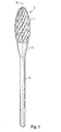
- the dental instrument according to the invention comprises a metallic, cylindrical shaft 3, which is designed and dimensioned in a conventional manner.
- the shaft 3 can be clamped in a drive device, for example an angle piece.
- the shaft 3 is connected at its end region with a diameter-enlarged connection region 11.
- a head 2 is attached from a ceramic material.
- the head 2 may be formed in the usual way, as shown in the prior art.
- the head 2 has a plurality of blades. 1 it may be cylindrical, rounded, spherical, spherical or otherwise formed.
- Reference numeral 10 denotes the center axis / rotation axis.
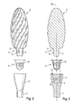
- FIGS. 2 and 3 show a schematic exploded view, wherein the head 2 is shown as a cylindrical blank, which is not the in Fig. 1 has shown finished shape with the blades 1.
- a fastening lug 4 is formed, which has a cylindrical basic shape and is provided with an external thread 5.
- the external thread 5 may be configured for example as a round thread.
- a contact surface 12 Adjacent to the attachment lug 4, a contact surface 12 is formed, which is configured conical and is designed to fit a contact surface 13 of the connection region 11 of the shaft 3. This results in a sealing contact between the head 2 and the shaft 3, so that a seamless connection (in particular bonding) is possible.
- the shaft 3 has a threaded recess 6 which is formed to match the external thread 5.
- a securing recess 7 is provided in the region of the internal thread of the threaded recess 6, which is formed in the form of an undercut annular groove.
- FIGS. 2 and 3 further show a securing element 8, which results by introducing a curable material when screwing the external thread 5 into a thread 14 of the threaded recess 6.
- a curable adhesive is introduced into the threaded recess 6 or applied to the mounting lug 4.
- this material which forms the fuse element 8 after curing, squeezed into the resulting spaces, in particular in the securing recess 7. It thus forms a fuse element 8, as in the FIGS. 2 and 3 is shown.
- a decompression recess 9 is provided, which may be formed, for example, in the form of a flattening or an axial groove of the fastening lug 4. As a result, excess material of the fuse element (adhesive) is pressed out.
- securing element 8 does not necessarily have to be formed in this physical form. It is sufficient if the securing recess 7 (undercut, annular groove, etc.) is completely filled with the material of the securing element. In the embodiment shown, an annular bead 15 is formed on the securing element 8, which is located in the annular groove 7 (securing recess) and otherwise blocks an axial movement. Depending on the game between the external thread 5 of the attachment lug 4 and the dimensioning of the threaded recess 6 may additionally in the FIGS. 2 and 3 shown cap-shaped or cup-shaped design result. Overall, it is inventively crucial that in the contact area between the external thread 5 of the mounting lug 4 and the internal thread 14, the threaded recess 6 is provided a form-fitting a releasing rotation preventing securing element.
- the material of the securing element may be formed as a multi-component material, which cures automatically. However, it is also possible to use material which is curable, for example, by the action of heat. Also, a heat-liquefiable material, e.g. a solder material is usable in the present invention.
- connection between the head and the shaft when using an adhesive material as the material for the securing element by conventional adhesion by adhesion or similar effects.
- the positive locking element according to the invention serves to prevent unscrewing and loosening of the thread in the event that the adhesive bond (joint connection) should be released by forces occurring, by vibrations, by the effect of temperature or other effects.
Landscapes
- Health & Medical Sciences (AREA)
- Engineering & Computer Science (AREA)
- Mechanical Engineering (AREA)
- Oral & Maxillofacial Surgery (AREA)
- Dentistry (AREA)
- Epidemiology (AREA)
- Life Sciences & Earth Sciences (AREA)
- Animal Behavior & Ethology (AREA)
- General Health & Medical Sciences (AREA)
- Public Health (AREA)
- Veterinary Medicine (AREA)
- Dental Prosthetics (AREA)
Applications Claiming Priority (1)
| Application Number | Priority Date | Filing Date | Title |
|---|---|---|---|
| DE102011010897.1A DE102011010897B4 (de) | 2011-02-10 | 2011-02-10 | Dentalinstrument sowie Verfahren zu dessen Herstellung |
Publications (3)
| Publication Number | Publication Date |
|---|---|
| EP2486888A2 true EP2486888A2 (fr) | 2012-08-15 |
| EP2486888A3 EP2486888A3 (fr) | 2015-05-06 |
| EP2486888B1 EP2486888B1 (fr) | 2016-06-08 |
Family
ID=45495718
Family Applications (1)
| Application Number | Title | Priority Date | Filing Date |
|---|---|---|---|
| EP12000008.8A Active EP2486888B1 (fr) | 2011-02-10 | 2012-01-02 | Instrument dentaire et méthode pour sa fabrication |
Country Status (4)
| Country | Link |
|---|---|
| US (1) | US9572634B2 (fr) |
| EP (1) | EP2486888B1 (fr) |
| DE (1) | DE102011010897B4 (fr) |
| ES (1) | ES2586584T3 (fr) |
Cited By (1)
| Publication number | Priority date | Publication date | Assignee | Title |
|---|---|---|---|---|
| WO2019052982A1 (fr) * | 2017-09-14 | 2019-03-21 | Franz Haimer Maschinenbau Kg | Insert fileté permettant de fixer un outil dans un logement d'outil et logement d'outil doté d'un tel insert fileté |
Families Citing this family (14)
| Publication number | Priority date | Publication date | Assignee | Title |
|---|---|---|---|---|
| DE102012100976B4 (de) | 2012-02-07 | 2014-04-24 | Franz Haimer Maschinenbau Kg | Einschraubwerkzeug und Werkzeugaufnahme für ein derartiges Einschraubwerkzeug |
| US9802256B2 (en) * | 2012-02-07 | 2017-10-31 | Franz Haimer Maschinenbau Kg | Screw-in tool and tool holder for such a screw-in tool |
| CA2883872A1 (fr) * | 2012-09-07 | 2014-03-13 | Stryker Ireland, Ltd. | Fraise chirurgicale comportant des goujures ayant des surfaces de rateau ayant un angle d'helice et un angle de rateau qui varient |
| US9643264B2 (en) | 2013-07-25 | 2017-05-09 | Kennametal Inc. | Coupling mechanism for cutting tool |
| US9643262B2 (en) | 2013-07-25 | 2017-05-09 | Kennametal Inc. | Coupling mechanism for cutting tool |
| DE102013225947A1 (de) | 2013-12-13 | 2015-06-18 | Busch & Co. Gmbh & Co. Kg | Werkzeugeinsatz |
| DE102014207502B4 (de) * | 2014-04-17 | 2022-11-24 | Kennametal Inc. | Rotationswerkzeug sowie Werkzeugkopf |
| US9889509B2 (en) | 2014-05-05 | 2018-02-13 | Kennametal Inc. | Cutter heads with improved coupling |
| US10828129B2 (en) | 2014-08-08 | 2020-11-10 | W&H Dentalwerk Bürmoos GmbH | Tool-coupling device for a vibration transferring handpiece |
| EP2982334B1 (fr) * | 2014-08-08 | 2017-02-01 | W & H Dentalwerk Bürmoos GmbH | Dispositif d'accouplement destiné à la transmission d'un mouvement d'entraînement d'une pièce à main transmettant des vibrations à un outil médical, en particulier dentaire |
| KR20180016342A (ko) * | 2015-06-12 | 2018-02-14 | 미쓰비시 마테리알 가부시키가이샤 | 테이퍼 엔드 밀 및 절삭 헤드 |
| KR102391515B1 (ko) * | 2015-07-31 | 2022-04-27 | 삼성전자주식회사 | 와이어 클램프용 클리닝 장치 및 이를 포함하는 클리닝 시스템 |
| DE102019220092A1 (de) * | 2019-12-18 | 2021-06-24 | MAPAL Fabrik für Präzisionswerkzeuge Dr. Kress KG | Werkzeugteil zur Verbindung mit einem Werkzeuggegenstück, Werkzeuggegenstück zur Verbindung mit einem Werkzeugteil, und Werkzeug |
| DE102020123848A1 (de) * | 2020-06-04 | 2021-12-23 | Ngmedical Gmbh | Monolithischer zervikaler oder lumbaler Implantatkörper |
Family Cites Families (43)
| Publication number | Priority date | Publication date | Assignee | Title |
|---|---|---|---|---|
| US170178A (en) * | 1875-11-23 | Improvement in dental polishing-tools | ||
| US1191717A (en) | 1915-10-15 | 1916-07-18 | John B Moore | Tool. |
| US2086133A (en) * | 1935-07-24 | 1937-07-06 | Frank J Kennedy | Connection or joint |
| US2177100A (en) * | 1938-09-21 | 1939-10-24 | Nat Supply Co | Leak-resisting pipe thread |
| US2380690A (en) * | 1943-09-13 | 1945-07-31 | Nat Tube Co | Pipe joint |
| US2506477A (en) * | 1944-03-15 | 1950-05-02 | Jr Richard F Warren | Lock nut |
| US2695452A (en) * | 1953-06-09 | 1954-11-30 | Kerr Mfg Company | Dental tool |
| US2942640A (en) | 1958-05-16 | 1960-06-28 | Edgar C Lundeberg | Lock nut having a deformable member containing liquid sealant |
| US3047316A (en) * | 1958-10-01 | 1962-07-31 | Atlas Bradford Company | Packed pin and box drill pipe coupling with means preventing extrusion of packing ring |
| FR1237569A (fr) * | 1958-10-14 | 1960-07-29 | Ruban lubrifiant et d'étanchéité pour joint fileté | |
| US3142138A (en) * | 1963-05-08 | 1964-07-28 | Wallace R Kean | Mounted abrasive stone and method of making same |
| US3339003A (en) * | 1964-06-01 | 1967-08-29 | Hi Shear Corp | Sealing of threaded fasteners |
| US3414034A (en) * | 1966-05-23 | 1968-12-03 | Rex Chainbelt Inc | Lock ring for threaded members |
| US3566947A (en) * | 1969-04-29 | 1971-03-02 | John A Jukes | Self-locking threaded insert |
| US3687493A (en) * | 1971-03-01 | 1972-08-29 | Exxon Production Research Co | Threaded connection |
| US3850054A (en) * | 1971-03-11 | 1974-11-26 | B Weissman | Composite drill |
| CH559872A5 (fr) * | 1972-10-11 | 1975-03-14 | Schell Hubert Kg | |
| DE2331023C3 (de) * | 1973-06-18 | 1978-08-17 | Horst Prof. Dr.Med.Dent. 6300 Giessen Kirschner | Bohr- bzw. Fräsapparat für die Zahnheilkunde |
| US4011121A (en) * | 1975-04-30 | 1977-03-08 | Phillips Petroleum Company | Adhesive bonding of poly(arylene sulfide) surfaces |
| FR2571467B1 (fr) * | 1984-10-10 | 1987-03-20 | Vallourec | Joint filete pour tube d'acier comportant un dispositif d'etancheite au niveau des filetages |
| FR2587080B1 (fr) * | 1985-09-12 | 1989-08-04 | Vallourec | Joint filete pour tubes d'acier comportant un dispositif d'etancheite localise au niveau de filetages |
| US5028162A (en) * | 1988-02-29 | 1991-07-02 | Ngk Insulators, Ltd. | Metal-ceramic joined composite bodies |
| US5106130A (en) * | 1988-06-28 | 1992-04-21 | A. O. Smith Corporation | Composite thread coupling for reinforced pipe |
| US5114286A (en) * | 1991-08-13 | 1992-05-19 | Calkins Donald W | Interchangeable tool alignment system |
| IL106697A (en) | 1993-08-15 | 1996-10-16 | Iscar Ltd | A cutting board with an integral lining |
| US5407312A (en) * | 1993-10-04 | 1995-04-18 | Terrizzi; A. Scott | Fastener system with an entrainable function-facilitating material |
| SE509218C2 (sv) * | 1994-08-29 | 1998-12-21 | Sandvik Ab | Skaftverktyg |
| US6106291A (en) * | 1998-12-15 | 2000-08-22 | Temple University Of The Commonwealth System Of Higher Education | Selective dentin caries excavator |
| US6565291B2 (en) * | 2000-08-18 | 2003-05-20 | Iscar, Ltd. | Cutting tool assembly |
| DE10243104A1 (de) * | 2002-09-17 | 2004-03-25 | Gebr. Brasseler Gmbh & Co. Kg | Rotierendes Instrument aus Keramik |
| SE528245C2 (sv) | 2004-09-23 | 2006-10-03 | Seco Tools Ab | Verktygshuvud med fattningsparti med axiella och radiella stoppytor |
| DE102004047909A1 (de) * | 2004-09-29 | 2006-04-13 | Bredent Dentalgeräte u. Materialien Fach- u. Organisationsberatung Peter Brehm | Bohrer für medizinische und zahnmedizinische Zwecke |
| ES2378432T3 (es) * | 2004-11-16 | 2012-04-12 | Straumann Holding Ag | Sistema de implante dental |
| US7473049B2 (en) * | 2006-01-30 | 2009-01-06 | Hamilton Sundstrand | Ceramic-to-metal shaft assembly |
| SE530043C2 (sv) * | 2006-04-20 | 2008-02-12 | Sandvik Intellectual Property | Verktyg för spånavskiljande bearbetning samt del därtill |
| CN101448469A (zh) * | 2006-05-23 | 2009-06-03 | 学校法人日本大学 | 牙科用切削杆 |
| DE102006049581A1 (de) * | 2006-10-20 | 2008-04-24 | Gebr. Brasseler Gmbh & Co. Kg | Rotierendes dental-chirurgisches Instrument |
| US7841259B2 (en) * | 2006-12-27 | 2010-11-30 | Baker Hughes Incorporated | Methods of forming bit bodies |
| US7887354B2 (en) * | 2008-08-11 | 2011-02-15 | Holliday Randall A | Thread lock for cable connectors |
| US20100151421A1 (en) * | 2008-12-12 | 2010-06-17 | Plastic Dental Corporation | Dental implant |
| JP4873268B2 (ja) * | 2008-12-27 | 2012-02-08 | 株式会社松風 | 歯科技工用カーバイドバー |
| DE102009034202B3 (de) * | 2009-07-16 | 2010-09-23 | Hartmetall-Werkzeugfabrik Paul Horn Gmbh | Zweiteiliges Werkzeug für spanende Bearbeitung mit Schraubkupplung |
| DE102010015934A1 (de) * | 2010-03-11 | 2011-09-15 | Gühring Ohg | Schnittstelle zur verdrehsicheren Ankopplung eines Werkzeugschafts an einen Werkzeug-Spannmodul, Komponenten zur Ausbildung der Schnittstelle und Verfahren zur Herstellung der Schnittstelle |
-
2011
- 2011-02-10 DE DE102011010897.1A patent/DE102011010897B4/de active Active
-
2012
- 2012-01-02 EP EP12000008.8A patent/EP2486888B1/fr active Active
- 2012-01-02 ES ES12000008.8T patent/ES2586584T3/es active Active
- 2012-02-08 US US13/369,081 patent/US9572634B2/en active Active
Non-Patent Citations (1)
| Title |
|---|
| None |
Cited By (3)
| Publication number | Priority date | Publication date | Assignee | Title |
|---|---|---|---|---|
| WO2019052982A1 (fr) * | 2017-09-14 | 2019-03-21 | Franz Haimer Maschinenbau Kg | Insert fileté permettant de fixer un outil dans un logement d'outil et logement d'outil doté d'un tel insert fileté |
| CN111093869A (zh) * | 2017-09-14 | 2020-05-01 | 弗兰茨·翰默机械制造两合公司 | 用于将工具紧固在工具接纳区域中的螺纹式插入件以及包括此类螺纹式插入件的工具接纳区域 |
| US11358228B2 (en) | 2017-09-14 | 2022-06-14 | Franz Haimer Maschinenbau Kg | Threaded insert for securing a tool in a tool receiving area, and tool receiving area comprising such a threaded insert |
Also Published As
| Publication number | Publication date |
|---|---|
| DE102011010897B4 (de) | 2023-02-09 |
| EP2486888B1 (fr) | 2016-06-08 |
| US9572634B2 (en) | 2017-02-21 |
| EP2486888A3 (fr) | 2015-05-06 |
| ES2586584T3 (es) | 2016-10-17 |
| DE102011010897A1 (de) | 2012-08-16 |
| US20120208147A1 (en) | 2012-08-16 |
Similar Documents
| Publication | Publication Date | Title |
|---|---|---|
| EP2486888B1 (fr) | Instrument dentaire et méthode pour sa fabrication | |
| EP2509532B1 (fr) | Implant dentaire | |
| EP2735279B1 (fr) | Implant dentaire | |
| DE102007044852B4 (de) | Dentalimplantat | |
| EP2090263A1 (fr) | Butée dotée d'un inlay pour implants dentaires | |
| EP3122271B1 (fr) | Procédé de fabrication d'un implant pour l'ostéosynthèse et clou orthopédique | |
| EP3302343B1 (fr) | Système de prothèse dentaire | |
| EP2143398A1 (fr) | Implant dentaire avec element intermédiaire élastique | |
| EP1903977A1 (fr) | Implant dentaire | |
| EP3634299B1 (fr) | Prothèse dentaire | |
| DE10323169A1 (de) | Vorrichtung zum Verbinden von Maschinenteilen | |
| DE19712426C1 (de) | Schraubverbindung | |
| EP2113221B1 (fr) | Implant dentaire en matière céramique | |
| EP2793732A2 (fr) | Système d'ancrage d'une prothèse dentaire et base de collage associée | |
| EP1903978A1 (fr) | Procede pour fixer un element medical dans un implant, et element medical | |
| DE102016004962A1 (de) | Fügeelement zum Direktverschrauben von Bauteilen | |
| DE102005011917A1 (de) | Dentalinstrument | |
| DE102006040516A1 (de) | Verbindungselement für Abutment und Implantat sowie ein Implantatsystem | |
| WO2014111227A1 (fr) | Tige d'un instrument dentaire | |
| DE102018008291A1 (de) | Befestigungselement mit mehrkantigem Außengewinde, Verfahren zu seiner Herstellung sowie Verbundelement und dessen Verwendung | |
| DE102018220074A1 (de) | Lenkgetriebe und Verfahren zur Montage eines solchen Lenkgetriebes | |
| DE10331445B4 (de) | Zahnstangenlenkgetriebe mit Einstellmutter und Verfahren zur Herstellung eines derartigen Zahnstangenlenkgetriebes | |
| DE102012015355A1 (de) | Schraubverbindung | |
| DE102009010879A1 (de) | Befestigungsanordnung eines Kegelzapfens | |
| DE10337672A1 (de) | Knochenhohlschraube |
Legal Events
| Date | Code | Title | Description |
|---|---|---|---|
| PUAI | Public reference made under article 153(3) epc to a published international application that has entered the european phase |
Free format text: ORIGINAL CODE: 0009012 |
|
| AK | Designated contracting states |
Kind code of ref document: A2 Designated state(s): AL AT BE BG CH CY CZ DE DK EE ES FI FR GB GR HR HU IE IS IT LI LT LU LV MC MK MT NL NO PL PT RO RS SE SI SK SM TR |
|
| AX | Request for extension of the european patent |
Extension state: BA ME |
|
| PUAL | Search report despatched |
Free format text: ORIGINAL CODE: 0009013 |
|
| AK | Designated contracting states |
Kind code of ref document: A3 Designated state(s): AL AT BE BG CH CY CZ DE DK EE ES FI FR GB GR HR HU IE IS IT LI LT LU LV MC MK MT NL NO PL PT RO RS SE SI SK SM TR |
|
| AX | Request for extension of the european patent |
Extension state: BA ME |
|
| RIC1 | Information provided on ipc code assigned before grant |
Ipc: A61C 3/02 20060101AFI20150330BHEP |
|
| 17P | Request for examination filed |
Effective date: 20150610 |
|
| RBV | Designated contracting states (corrected) |
Designated state(s): AL AT BE BG CH CY CZ DE DK EE ES FI FR GB GR HR HU IE IS IT LI LT LU LV MC MK MT NL NO PL PT RO RS SE SI SK SM TR |
|
| GRAP | Despatch of communication of intention to grant a patent |
Free format text: ORIGINAL CODE: EPIDOSNIGR1 |
|
| RIC1 | Information provided on ipc code assigned before grant |
Ipc: A61C 3/02 20060101AFI20160208BHEP |
|
| INTG | Intention to grant announced |
Effective date: 20160309 |
|
| RIN1 | Information on inventor provided before grant (corrected) |
Inventor name: KRUMSIEK, MICHAEL |
|
| GRAS | Grant fee paid |
Free format text: ORIGINAL CODE: EPIDOSNIGR3 |
|
| GRAA | (expected) grant |
Free format text: ORIGINAL CODE: 0009210 |
|
| AK | Designated contracting states |
Kind code of ref document: B1 Designated state(s): AL AT BE BG CH CY CZ DE DK EE ES FI FR GB GR HR HU IE IS IT LI LT LU LV MC MK MT NL NO PL PT RO RS SE SI SK SM TR |
|
| REG | Reference to a national code |
Ref country code: GB Ref legal event code: FG4D Free format text: NOT ENGLISH |
|
| REG | Reference to a national code |
Ref country code: CH Ref legal event code: EP |
|
| REG | Reference to a national code |
Ref country code: IE Ref legal event code: FG4D Free format text: LANGUAGE OF EP DOCUMENT: GERMAN |
|
| REG | Reference to a national code |
Ref country code: AT Ref legal event code: REF Ref document number: 804670 Country of ref document: AT Kind code of ref document: T Effective date: 20160715 |
|
| REG | Reference to a national code |
Ref country code: DE Ref legal event code: R096 Ref document number: 502012007327 Country of ref document: DE |
|
| REG | Reference to a national code |
Ref country code: CH Ref legal event code: NV Representative=s name: KELLER AND PARTNER PATENTANWAELTE AG, CH |
|
| REG | Reference to a national code |
Ref country code: LT Ref legal event code: MG4D |
|
| REG | Reference to a national code |
Ref country code: NL Ref legal event code: MP Effective date: 20160608 |
|
| REG | Reference to a national code |
Ref country code: ES Ref legal event code: FG2A Ref document number: 2586584 Country of ref document: ES Kind code of ref document: T3 Effective date: 20161017 |
|
| PG25 | Lapsed in a contracting state [announced via postgrant information from national office to epo] |
Ref country code: FI Free format text: LAPSE BECAUSE OF FAILURE TO SUBMIT A TRANSLATION OF THE DESCRIPTION OR TO PAY THE FEE WITHIN THE PRESCRIBED TIME-LIMIT Effective date: 20160608 Ref country code: LT Free format text: LAPSE BECAUSE OF FAILURE TO SUBMIT A TRANSLATION OF THE DESCRIPTION OR TO PAY THE FEE WITHIN THE PRESCRIBED TIME-LIMIT Effective date: 20160608 Ref country code: NO Free format text: LAPSE BECAUSE OF FAILURE TO SUBMIT A TRANSLATION OF THE DESCRIPTION OR TO PAY THE FEE WITHIN THE PRESCRIBED TIME-LIMIT Effective date: 20160908 |
|
| PG25 | Lapsed in a contracting state [announced via postgrant information from national office to epo] |
Ref country code: LV Free format text: LAPSE BECAUSE OF FAILURE TO SUBMIT A TRANSLATION OF THE DESCRIPTION OR TO PAY THE FEE WITHIN THE PRESCRIBED TIME-LIMIT Effective date: 20160608 Ref country code: NL Free format text: LAPSE BECAUSE OF FAILURE TO SUBMIT A TRANSLATION OF THE DESCRIPTION OR TO PAY THE FEE WITHIN THE PRESCRIBED TIME-LIMIT Effective date: 20160608 Ref country code: RS Free format text: LAPSE BECAUSE OF FAILURE TO SUBMIT A TRANSLATION OF THE DESCRIPTION OR TO PAY THE FEE WITHIN THE PRESCRIBED TIME-LIMIT Effective date: 20160608 Ref country code: SE Free format text: LAPSE BECAUSE OF FAILURE TO SUBMIT A TRANSLATION OF THE DESCRIPTION OR TO PAY THE FEE WITHIN THE PRESCRIBED TIME-LIMIT Effective date: 20160608 Ref country code: GR Free format text: LAPSE BECAUSE OF FAILURE TO SUBMIT A TRANSLATION OF THE DESCRIPTION OR TO PAY THE FEE WITHIN THE PRESCRIBED TIME-LIMIT Effective date: 20160909 Ref country code: HR Free format text: LAPSE BECAUSE OF FAILURE TO SUBMIT A TRANSLATION OF THE DESCRIPTION OR TO PAY THE FEE WITHIN THE PRESCRIBED TIME-LIMIT Effective date: 20160608 |
|
| REG | Reference to a national code |
Ref country code: FR Ref legal event code: PLFP Year of fee payment: 6 |
|
| PG25 | Lapsed in a contracting state [announced via postgrant information from national office to epo] |
Ref country code: CZ Free format text: LAPSE BECAUSE OF FAILURE TO SUBMIT A TRANSLATION OF THE DESCRIPTION OR TO PAY THE FEE WITHIN THE PRESCRIBED TIME-LIMIT Effective date: 20160608 Ref country code: IS Free format text: LAPSE BECAUSE OF FAILURE TO SUBMIT A TRANSLATION OF THE DESCRIPTION OR TO PAY THE FEE WITHIN THE PRESCRIBED TIME-LIMIT Effective date: 20161008 Ref country code: RO Free format text: LAPSE BECAUSE OF FAILURE TO SUBMIT A TRANSLATION OF THE DESCRIPTION OR TO PAY THE FEE WITHIN THE PRESCRIBED TIME-LIMIT Effective date: 20160608 Ref country code: EE Free format text: LAPSE BECAUSE OF FAILURE TO SUBMIT A TRANSLATION OF THE DESCRIPTION OR TO PAY THE FEE WITHIN THE PRESCRIBED TIME-LIMIT Effective date: 20160608 Ref country code: SK Free format text: LAPSE BECAUSE OF FAILURE TO SUBMIT A TRANSLATION OF THE DESCRIPTION OR TO PAY THE FEE WITHIN THE PRESCRIBED TIME-LIMIT Effective date: 20160608 |
|
| PG25 | Lapsed in a contracting state [announced via postgrant information from national office to epo] |
Ref country code: PT Free format text: LAPSE BECAUSE OF FAILURE TO SUBMIT A TRANSLATION OF THE DESCRIPTION OR TO PAY THE FEE WITHIN THE PRESCRIBED TIME-LIMIT Effective date: 20161010 Ref country code: SM Free format text: LAPSE BECAUSE OF FAILURE TO SUBMIT A TRANSLATION OF THE DESCRIPTION OR TO PAY THE FEE WITHIN THE PRESCRIBED TIME-LIMIT Effective date: 20160608 Ref country code: PL Free format text: LAPSE BECAUSE OF FAILURE TO SUBMIT A TRANSLATION OF THE DESCRIPTION OR TO PAY THE FEE WITHIN THE PRESCRIBED TIME-LIMIT Effective date: 20160608 |
|
| REG | Reference to a national code |
Ref country code: DE Ref legal event code: R097 Ref document number: 502012007327 Country of ref document: DE |
|
| PLBE | No opposition filed within time limit |
Free format text: ORIGINAL CODE: 0009261 |
|
| STAA | Information on the status of an ep patent application or granted ep patent |
Free format text: STATUS: NO OPPOSITION FILED WITHIN TIME LIMIT |
|
| 26N | No opposition filed |
Effective date: 20170309 |
|
| PG25 | Lapsed in a contracting state [announced via postgrant information from national office to epo] |
Ref country code: BE Free format text: LAPSE BECAUSE OF NON-PAYMENT OF DUE FEES Effective date: 20170131 Ref country code: SI Free format text: LAPSE BECAUSE OF FAILURE TO SUBMIT A TRANSLATION OF THE DESCRIPTION OR TO PAY THE FEE WITHIN THE PRESCRIBED TIME-LIMIT Effective date: 20160608 Ref country code: DK Free format text: LAPSE BECAUSE OF FAILURE TO SUBMIT A TRANSLATION OF THE DESCRIPTION OR TO PAY THE FEE WITHIN THE PRESCRIBED TIME-LIMIT Effective date: 20160608 |
|
| GBPC | Gb: european patent ceased through non-payment of renewal fee |
Effective date: 20170102 |
|
| PG25 | Lapsed in a contracting state [announced via postgrant information from national office to epo] |
Ref country code: MC Free format text: LAPSE BECAUSE OF FAILURE TO SUBMIT A TRANSLATION OF THE DESCRIPTION OR TO PAY THE FEE WITHIN THE PRESCRIBED TIME-LIMIT Effective date: 20160608 |
|
| REG | Reference to a national code |
Ref country code: IE Ref legal event code: MM4A |
|
| PG25 | Lapsed in a contracting state [announced via postgrant information from national office to epo] |
Ref country code: LU Free format text: LAPSE BECAUSE OF NON-PAYMENT OF DUE FEES Effective date: 20170102 Ref country code: GB Free format text: LAPSE BECAUSE OF NON-PAYMENT OF DUE FEES Effective date: 20170102 |
|
| REG | Reference to a national code |
Ref country code: FR Ref legal event code: PLFP Year of fee payment: 7 |
|
| REG | Reference to a national code |
Ref country code: BE Ref legal event code: MM Effective date: 20170131 |
|
| PG25 | Lapsed in a contracting state [announced via postgrant information from national office to epo] |
Ref country code: IE Free format text: LAPSE BECAUSE OF NON-PAYMENT OF DUE FEES Effective date: 20170102 |
|
| PG25 | Lapsed in a contracting state [announced via postgrant information from national office to epo] |
Ref country code: MT Free format text: LAPSE BECAUSE OF FAILURE TO SUBMIT A TRANSLATION OF THE DESCRIPTION OR TO PAY THE FEE WITHIN THE PRESCRIBED TIME-LIMIT Effective date: 20160608 |
|
| PG25 | Lapsed in a contracting state [announced via postgrant information from national office to epo] |
Ref country code: AL Free format text: LAPSE BECAUSE OF FAILURE TO SUBMIT A TRANSLATION OF THE DESCRIPTION OR TO PAY THE FEE WITHIN THE PRESCRIBED TIME-LIMIT Effective date: 20160608 |
|
| PG25 | Lapsed in a contracting state [announced via postgrant information from national office to epo] |
Ref country code: HU Free format text: LAPSE BECAUSE OF FAILURE TO SUBMIT A TRANSLATION OF THE DESCRIPTION OR TO PAY THE FEE WITHIN THE PRESCRIBED TIME-LIMIT; INVALID AB INITIO Effective date: 20120102 |
|
| PG25 | Lapsed in a contracting state [announced via postgrant information from national office to epo] |
Ref country code: BG Free format text: LAPSE BECAUSE OF FAILURE TO SUBMIT A TRANSLATION OF THE DESCRIPTION OR TO PAY THE FEE WITHIN THE PRESCRIBED TIME-LIMIT Effective date: 20160608 |
|
| PG25 | Lapsed in a contracting state [announced via postgrant information from national office to epo] |
Ref country code: CY Free format text: LAPSE BECAUSE OF NON-PAYMENT OF DUE FEES Effective date: 20160608 |
|
| PG25 | Lapsed in a contracting state [announced via postgrant information from national office to epo] |
Ref country code: MK Free format text: LAPSE BECAUSE OF FAILURE TO SUBMIT A TRANSLATION OF THE DESCRIPTION OR TO PAY THE FEE WITHIN THE PRESCRIBED TIME-LIMIT Effective date: 20160608 |
|
| PG25 | Lapsed in a contracting state [announced via postgrant information from national office to epo] |
Ref country code: TR Free format text: LAPSE BECAUSE OF FAILURE TO SUBMIT A TRANSLATION OF THE DESCRIPTION OR TO PAY THE FEE WITHIN THE PRESCRIBED TIME-LIMIT Effective date: 20160608 |
|
| REG | Reference to a national code |
Ref country code: CH Ref legal event code: PFA Owner name: GEBR. BRASSELER GMBH AND CO. KG, DE Free format text: FORMER OWNER: GEBR. BRASSELER GMBH AND CO. KG, DE |
|
| P01 | Opt-out of the competence of the unified patent court (upc) registered |
Effective date: 20230427 |
|
| PGFP | Annual fee paid to national office [announced via postgrant information from national office to epo] |
Ref country code: ES Payment date: 20240216 Year of fee payment: 13 |
|
| PGFP | Annual fee paid to national office [announced via postgrant information from national office to epo] |
Ref country code: AT Payment date: 20240118 Year of fee payment: 13 |
|
| PGFP | Annual fee paid to national office [announced via postgrant information from national office to epo] |
Ref country code: CH Payment date: 20240202 Year of fee payment: 13 |
|
| PGFP | Annual fee paid to national office [announced via postgrant information from national office to epo] |
Ref country code: IT Payment date: 20240131 Year of fee payment: 13 |
|
| REG | Reference to a national code |
Ref country code: CH Ref legal event code: PL |
|
| REG | Reference to a national code |
Ref country code: AT Ref legal event code: MM01 Ref document number: 804670 Country of ref document: AT Kind code of ref document: T Effective date: 20250102 |
|
| PG25 | Lapsed in a contracting state [announced via postgrant information from national office to epo] |
Ref country code: AT Free format text: LAPSE BECAUSE OF NON-PAYMENT OF DUE FEES Effective date: 20250102 |
|
| PG25 | Lapsed in a contracting state [announced via postgrant information from national office to epo] |
Ref country code: CH Free format text: LAPSE BECAUSE OF NON-PAYMENT OF DUE FEES Effective date: 20250131 |
|
| PG25 | Lapsed in a contracting state [announced via postgrant information from national office to epo] |
Ref country code: IT Free format text: LAPSE BECAUSE OF NON-PAYMENT OF DUE FEES Effective date: 20250102 |
|
| REG | Reference to a national code |
Ref country code: ES Ref legal event code: FD2A Effective date: 20260226 |
|
| PG25 | Lapsed in a contracting state [announced via postgrant information from national office to epo] |
Ref country code: ES Free format text: LAPSE BECAUSE OF NON-PAYMENT OF DUE FEES Effective date: 20250103 |
|
| PGFP | Annual fee paid to national office [announced via postgrant information from national office to epo] |
Ref country code: DE Payment date: 20260128 Year of fee payment: 15 |
|
| PGFP | Annual fee paid to national office [announced via postgrant information from national office to epo] |
Ref country code: FR Payment date: 20260121 Year of fee payment: 15 |