EP2486987B1 - Saugschlitzkanalabsaugsystem - Google Patents
Saugschlitzkanalabsaugsystem Download PDFInfo
- Publication number
- EP2486987B1 EP2486987B1 EP12000636.6A EP12000636A EP2486987B1 EP 2486987 B1 EP2486987 B1 EP 2486987B1 EP 12000636 A EP12000636 A EP 12000636A EP 2486987 B1 EP2486987 B1 EP 2486987B1
- Authority
- EP
- European Patent Office
- Prior art keywords
- suction
- suction nozzle
- slotted
- connection
- nozzle
- Prior art date
- Legal status (The legal status is an assumption and is not a legal conclusion. Google has not performed a legal analysis and makes no representation as to the accuracy of the status listed.)
- Not-in-force
Links
- 238000007789 sealing Methods 0.000 claims description 28
- 238000000605 extraction Methods 0.000 claims description 5
- 239000002783 friction material Substances 0.000 claims description 5
- 239000002131 composite material Substances 0.000 claims description 4
- 239000013013 elastic material Substances 0.000 claims description 3
- 239000000126 substance Substances 0.000 claims 1
- 239000002759 woven fabric Substances 0.000 claims 1
- 239000011324 bead Substances 0.000 description 15
- 239000004744 fabric Substances 0.000 description 6
- 239000000835 fiber Substances 0.000 description 5
- 238000004140 cleaning Methods 0.000 description 2
- 239000000428 dust Substances 0.000 description 2
- 239000007789 gas Substances 0.000 description 2
- 239000002245 particle Substances 0.000 description 2
- 229920000728 polyester Polymers 0.000 description 2
- 238000013459 approach Methods 0.000 description 1
- 235000015173 baked goods and baking mixes Nutrition 0.000 description 1
- 239000011248 coating agent Substances 0.000 description 1
- 238000000576 coating method Methods 0.000 description 1
- 230000001419 dependent effect Effects 0.000 description 1
- 235000013305 food Nutrition 0.000 description 1
- 239000000463 material Substances 0.000 description 1
- 239000003973 paint Substances 0.000 description 1
- 239000000843 powder Substances 0.000 description 1
Images


Classifications
-
- B—PERFORMING OPERATIONS; TRANSPORTING
- B08—CLEANING
- B08B—CLEANING IN GENERAL; PREVENTION OF FOULING IN GENERAL
- B08B15/00—Preventing escape of dirt or fumes from the area where they are produced; Collecting or removing dirt or fumes from that area
- B08B15/002—Preventing escape of dirt or fumes from the area where they are produced; Collecting or removing dirt or fumes from that area using a central suction system, e.g. for collecting exhaust gases in workshops
- B08B15/005—Preventing escape of dirt or fumes from the area where they are produced; Collecting or removing dirt or fumes from that area using a central suction system, e.g. for collecting exhaust gases in workshops comprising a stationary main duct with one or more branch units, the branch units being freely movable along a sealed longitudinal slit in the main duct
Definitions
- the invention relates to a Saugschlitzkanalabsaugsystem with a guided in or on a Saugschlitzkanal suction nozzle, which is sealed relative to the channel by means of at least one sealing lip.
- a Saugschlitzkanal suction device is known, by means of which gases and vapors are sucked.
- a connected to a suction fan duct is attached to the ceiling of the factory seat, on which a movable intake is performed, to which in turn a suction hose is connected.
- the sealing of the intake manifold with respect to the channel takes place via a lip seal.
- a disadvantage of the aforementioned arrangements is that a reliable seal, is prevented in the dust, without that strong friction losses or frictions occur is not possible.
- the object of the invention is an improved Saugschlitzkanalabsaugsystem with a guided in or on a Saugschlitzkanal suction nozzle, which seals against the channel by means of at least one sealing lip, and a corresponding suction nozzle and a sealing lip for such a system to provide a better seal with easy handling is provided.
- the invention provides a Saugschlitzkanalabsaugsystem with a suction nozzle, which leads the suction nozzle in or on a Saugschlitzkanal which is sealed by means of at least one sealing lip against an intake manifold of the movably guided suction nozzle, wherein the Saugschlitzkanal-side end of the intake manifold has a protruding bead, the plant is provided at the / the sealing lips, wherein at least the bead of the intake manifold is provided with a textured non-planar surface, wherein the sealing lip consists of a composite material of an elastic material, wherein on the one past sliding intake manifold side facing a low-friction material is provided , wherein on the side facing a sliding intake nozzle side facing a corrugation or a fabric is arranged, whose the intake manifold directly facing corrugations or fibers are aligned in the direction of the sliding direction.
- the suction nozzle to the Saugschlitzkanal-side end in a spatial direction tapering flattening, and in a spatial direction perpendicular thereto widening and the opening of the intake in oval cross-section, tapering is designed.
- This will be a Low-suction, low-loss transfer from a suction hose connected to the suction nozzle via the suction nozzle to Saugschlitzkanal allows.
- the cross section of the flattening in a direction in space and in a vertical spatial direction widening thereto intake remains approximately the same.
- the low-friction material is a polyester fabric, wherein the fiber direction is arranged on the side facing the bead substantially in the direction of movement of the suction nozzle on Saugschlitzkanal.
- the sliding on the fabric of the composite material of the sealing lip is further improved. Due to the fiber arrangement perpendicular to the suction direction to Saugschlitzkanal-inside towards the seal of the sealing lips is also improved by juxtaposition of the opposite fibers of the sealing lips.
- the suction nozzle is guided in a positive guide on Saugschlitzkanal and has for this purpose according to a further development, in particular in a formed on or in Saugschlitzkanal slot guide rollers.
- the sealing lip is on its side facing the bead of the intake from as possible with respect to this low-friction material, in particular by a surface choice in the form of a corrugation or a tissue may be given a preference of sliding in the direction of movement of the suction nozzle on the slot channel.
- a corrugation or fabric structure can also improve the seal against the suction to the channel interior of the sealing lips.
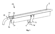
- Fig. 1 the entire Saugschlitzkanalabsaugsystem 11 is shown with a suction nozzle 1, which is guided via a suction carriage 4 to a suction slot 2 channel.
- the Saugschlitzkanal 2 is connected via a suction fan connection 22 with a suction fan (not shown).
- the suction hose is connected, which extends to near the bottom of the room in which the system is installed.
- FIG. 2 A schematic sectional view through the Saugschlitzkanalabsaugsystem 11 and the suction carriage 4 with attached suction nozzle 1 is in Fig. 2 shown.
- the Saugschlitzkanal-side end 14 of the intake manifold 12 of the suction nozzle 1 has a protruding bead 13 which rests against the sealing lips 31, 32.
- the sealing lips 31 and 32 are formed in the example on its side facing the bead 13 of the intake 12 from a possible low friction with respect to the bead surface material technical polyester fabric.
- Fig. 4a to 4c is the suction carriage 4 with the suction nozzle 1 and the intake manifold 12 shown at the end of the bead 13 from different perspectives.
- the approximately Navette-shaped bead 13 is opposite to the intake 12 via.
- the suction nozzle 1 or its intake manifold 12 is flattening tapered to Saugschlitzkanal-side end 14 out. On the one hand, it is tapered in a first spatial direction and in a spatial direction perpendicular thereto, designed to widen. As a result, the cross-sectional width is maintained without losses.
- the bead 13 on the intake 12 and the suction nozzle 1 is in the Fig. 5 to 7 again shown in more detail in different views and sections.
- the bead 13 and the intake manifold 12 are provided with a textured non-planar surface by a powder paint coating. This improves the sliding relative to the surface of the sealing lip (31, 32), which in the example consists of a composite material made of an elastic material, wherein on the side facing a sliding intake side facing a low-friction material is provided, which provided in the form of a fabric is, the intake manifold directly facing fibers are aligned in the direction of sliding.
Landscapes
- Absorbent Articles And Supports Therefor (AREA)
- Labeling Devices (AREA)
- Display Devices Of Pinball Game Machines (AREA)
- Supply And Installment Of Electrical Components (AREA)
Description
- Die Erfindung betrifft ein Saugschlitzkanalabsaugsystem mit einer in oder an einem Saugschlitzkanal geführten Saugdüse, welche gegenüber dem Kanal mittels mindestens einer Dichtlippe abgedichtet ist.
- Aus der
DE 44 22 731 ist eine Saugschlitzkanal-Absaugvorrichtung bekannt, vermittels welcher Gase und Dämpfe absaugbar sind. Dabei wird an der Decke der Werksatt ein an einem Sauggebläse angeschlossener Kanal befestigt, an dem ein beweglicher Ansaugstutzen geführt ist, an dem wiederum ein Saugschlauch angeschlossen ist. Die Abdichtung des Ansaugstutzens gegenüber dem Kanal erfolgt dabei über eine Lippendichtung. - Der Vorteil hierbei liegt darin, dass auf dem Werkstattboden keine unhandlichen Gerätschaften herumstehen.
- Bei Lebensmittelmärkten geht der Trend zu frisch aufgebackenen Backwaren, die naturgemäß eine Staub- und eine erhebliche Krümelbelastung des Verkaufsraums mit sich führen.
- Da bei starker Partikelbelastung hohe Saugleistungen und eine gute Systemabdichtung notwendig sind, sind die vorliegenden Ansätze zur reinen Gasabsaugung unzureichend. Auch sind die vorbekannten Lösungen schwerfällig und durch Reinigungspersonal nur bedingt bedienbar.
- Es besteht daher der Wunsch nach effizienten und hygienischen Reinigungseinrichtungen, die in Form von fest installierten Systemen bereitgestellt sind.
- Aus der
US 2007/0209545 A1 ist ein Saugkanalsystem bekannt, bei dem ein Schlitten in einem gegenüber diesem gegen die Umluft mit einer Art Lippendichtung abgedichteten Kanal geführt ist. - Aus der
DD 75140 A5 US 3,913,470 A ist jeweils ein Kanalabsaugsystem mit einem in einem Kanal geführten navetteförmigen Schlitten als Ansaugstutzen gezeigt. - Aus der
DE 1 843 766 U ist eine Absaugeinrichtung für hin- und herbewegte Maschinen bekannt, bei der ein Luftabnehmer gegen eine Dichtlippe abdichtend an einem Absaugrohr entlang gleitet. - Aus der
US 2007/0209545 A1 ist ein ähnliches Kanalabsaugsystem bekannt, bei dem ein Stutzen in einem Absaugrohr geführt ist und dabei gegen eine elastische Dichtlippe drückt. - Nachteilig bei den vorgenannten Anordnungen ist, dass eine verlässliche Abdichtung, bei der Staubaustritt verhindert ist, ohne, dass starke Reibungsverluste oder Friktionen auftreten nicht möglich ist.
- Aufgabe der Erfindung ist es, ein verbessertes Saugschlitzkanalabsaugsystem mit einer in oder an einem Saugschlitzkanal geführten Saugdüse, welche gegenüber dem Kanal mittels mindestens einer Dichtlippe abdichtet, sowie eine entsprechende Saugdüse und eine Dichtlippe für ein solches System zur Verfügung zu stellen, bei der eine bessere Abdichtung bei leichter Handhabung bereitgestellt ist.
- Diese Aufgabe wird durch ein Saugschlitzkanalabsaugsystem nach den Merkmalen des Anspruchs 1 gelöst.
- Erfindungsgemäß vorgesehen ist ein Saugschlitzkanalabsaugsystem mit einer Saugdüse, welches die Saugdüse in oder an einem Saugschlitzkanal führt, welcher mittels mindestens einer Dichtlippe gegenüber einem Ansaugstutzen der beweglich geführten Saugdüse abgedichtet ist, wobei das Saugschlitzkanal-seitige Ende des Ansaugstutzens einen überstehenden Wulst aufweist, der zur Anlage an der/den Dichtlippen vorgesehen ist, wobei wenigstens der Wulst des Ansaugstutzens mit einer strukturierten nichtplanen Oberfläche versehen ist, wobei die Dichtlippe aus einem Verbundwerkstoff aus einem elastischem Material besteht, wobei an der einem vorbei gleitendem Ansaugstutzen zugewandten Seite ein gegenüber diesem reibungsarmes Material vorgesehen ist, wobei an der einem vorbei gleitendem Ansaugstutzen zugewandten Seite eine Riffelung oder ein Gewebe angeordnet ist, dessen dem Ansaugstutzen unmittelbar zugewandte Riffeln oder Fasern in Richtung der Gleitrichtung ausgerichtet sind.
- Nach einer vorteilhaften Weiterbildung der Erfindung ist vorgeschlagen, dass die Saugdüse zum Saugschlitzkanal-seitigen Ende hin in einer Raumrichtung sich verjüngend abflachend , und in einer hierzu senkrechten Raumrichtung sich aufweitend und die Öffnung des Ansaugstutzens im Querschnitt oval, spitz zulaufend ausgestaltet ist. Hierdurch wird eine Saugleistungs-verlustarme Überführung von einem an der Saugdüse angeschlossenen Saugschlauch über die Saugdüse zum Saugschlitzkanal ermöglicht. Die vorgeschlagene Navette-ähnliche Form des Wulstes, also näherungsweise dem Schnitt zweier Kreisbögen, ermöglicht ein gutes Hindurchgleiten der Saugdüse bei beidseitig vorgesehenen Dichtlippen. Durch den Unterdruck im Saugschlitzkanal liegen die Dichtlippen vor und nach dem Ansaugstutzen der Saugdüse dichtend aneinander an. Mit der vorliegenden Erfindung ist sogar ein Einsatz mit Hochvakuum denkbar, da selbst bei den dann verstärkt auftretenden Kräften eine Beweglichkeit erhalten bleibt.
- Bevorzugterweise bleibt der Querschnitt des sich in einer Raumrichtung abflachenden und in einer senkrechten Raumrichtung hierzu aufweitenden Ansaugstutzens annähernd gleich.
- Vorteilhafterweise ist das reibungsarme Material ein Polyestergewebe, wobei die Faserrichtung an der dem Wulst zugewandten Seite im Wesentlichen in Bewegungsrichtung der Saugdüse am Saugschlitzkanal angeordnet ist. Hierdurch wird das Abgleiten auf dem Gewebe des Verbundstoffs der Dichtlippe nochmals verbessert. Durch die Faseranordnung senkrecht zur Saugrichtung zum Saugschlitzkanal-Inneren hin ist zudem nochmals die Abdichtung der Dichtlippen durch Aneinanderliegen der gegenüberliegenden Fasern der Dichtlippen verbessert.
- Von Vorteil ist die Saugdüse in einer Zwangsführung am Saugschlitzkanal geführt und weist hierzu nach einer Weiterbildung insbesondere in einer am oder im Saugschlitzkanal ausgebildeten Schlitzführung gelagerte Rollen auf. Bevorzugterweise besteht die Dichtlippe an ihrer dem Wulst des Ansaugstutzens zugewandten Seite aus möglichst gegenüber diesem reibungsarmen Material, wobei insbesondere noch durch eine Oberflächenwahl in Form eine Riffelung oder eines Gewebes eine Bevorzugung des Gleitens in Bewegungsrichtung der Saugdüse am Schlitzkanal gegeben sein kann. Eine solche Riffelung oder Gewebestruktur kann auch der Abdichtung gegen die Saugwirkung zum Kanalinneren der Dichtlippen verbessern.
- Weitere vorteilhafte Ausgestaltungen ergeben sich aus den weiteren Unteransprüchen oder deren mögliche Unterkombinationen.
- Nachfolgend wird die Erfindung anhand der Zeichnungen weiter erläutert. Im Einzelnen zeigt die schematische Darstellung in:
- Fig. 1
- eine schematische Darstellung eines erfindungsgemäßen Saugschlitzkanalabsaugsystems mit einem eine erfindungsgemäße Saugdüse aufweisenden Saugwagen,
- Fig. 2
- eine schematische Schnittdarstellung durch das Saugschlitzkanalabsaugsystem aus
Fig. 1 im Bereich der Saugdüse bzw. des Saugwagens, - Fig. 3
- eine schematische Schnittdarstellung durch das Saugschlitzkanalabsaugsystem aus
Fig. 1 im Bereich des Saugschlitzkanals neben dem Saugwagen, - Fig. 4a bis 4c
- verschiedene Ansichten des Saugwagens mit Saugdüse,
- Fig. 5
- eine Draufsicht auf eine erfindungsgemäße Saugdüse,
- Fig. 5a
- eine schematische Schnittdarstellung durch die Saugdüse aus
Fig. 5 in Blickrichtung A, - Fig. 5b
- eine schematische Schnittdarstellung durch die Saugdüse aus
Fig. 5 in Blickrichtung B, - Fig. 6a
- eine Ansicht der Saugdüse aus
Fig. 5 auf den Wulst, - Fig. 6b
- eine Ansicht der Saugdüse aus
Fig. 5 auf den Schlauchanschluss, und - Fig. 7
- eine schematische Schrägansicht der Saugdüse aus
Fig. 5 . - Die in den Figuren gleichen Bezugsziffern bezeichnen gleiche oder gleich wirkende Elemente.
- In
Fig. 1 ist das ganze Saugschlitzkanalabsaugsystem 11 mit einer Saugdüse 1 gezeigt, welche über einen Saugwagen 4 an einem Saugschlitzkanal 2 geführt ist. Der Saugschlitzkanal 2 wird dabei über einen Sauggebläseanschluss 22 mit einem Sauggebläse (nicht dargestellt) verbunden. - Die Abdichtung des Saugschlitzkanals 2 gegen die Saugdüse 1 erfolgt dabei durch die symmetrisch angeordneten flexiblen Dichtlippen 31 und 32. Im Bereich neben der Saugdüse liegen die Dichtlippen 31 und 32 aneinander dichtend an, siehe hierzu auch
Fig. 3 , in der ein Schnitt durch das Saugschlitzkanalabsaugsystem 11 neben dem Saugwagen 4 gezeigt ist. Der Saugschlitzkanal 2 ist vermittels der aneinanderliegenden Dichtlippen 31 und 32 dicht verschlossen. Die Saugleistung wird so auch über längere Wege nicht verringert und die partikelbelastete Abluft kann im Saugschlitzkanal 2 sicher zum Sauggebläseanschluss 22 geleitet werden, ohne dass es zu Verschmutzung außerhalb des Saugschlitzkanals 2 durch freiwerdende Krümel oder Partikel kommt. - An dem an der Saugdüse 1 vorgesehenen Schlauchanschluss 16 wird dann der Saugschlauch angeschlossen, der bis nahe dem Boden des Raumes reicht, in dem das System installiert ist.
- Eine schematische Schnittdarstellung durch das Saugschlitzkanalabsaugsystem 11 und den Saugwagen 4 mit daran befestigter Saugdüse 1 ist in
Fig. 2 gezeigt. - Das Saugschlitzkanal-seitige Ende 14 des Ansaugstutzens 12 der Saugdüse 1 weist einen überstehenden Wulst 13 auf, der an den Dichtlippen 31, 32 anliegt.
- In dieser Schnittdarstellung ist auch gut ersichtlich, wie die Saugdüse 1 über den daran befestigten Saugwagen 4 in einer Zwangsführung am Saugschlitzkanal 2 geführt ist. Am Saugwagen 4 gelagerte Rollen 15 sind hierzu in einer am Saugschlitzkanal 2 ausgebildeten Schlitzführung 21 geführt.
- Die Dichtlippen 31 und 32 sind im Beispiel an ihrer dem Wulst 13 des Ansaugstutzens 12 zugewandten Seite aus einem möglichst gegenüber dem Wulst-Oberflächenmaterial reibungsarmen technischem Polyestergewebe ausgebildet.
- In den
Fig. 4a bis 4c ist der Saugwagen 4 mit der Saugdüse 1 und deren Ansaugstutzen 12 mit am Ende vorgesehenem Wulst 13 aus verschiedenen Blickrichtungen gezeigt. - Der annähernd Navette-förmige Wulst 13, steht gegenüber dem Ansaugstutzen 12 über.
- Die Saugdüse 1 bzw. deren Ansaugstutzen 12 ist sich abflachend verjüngend zum Saugschlitzkanal-seitigen Ende 14 hin ausgestaltet. Zum einen ist sie sich verjüngend in einer ersten Raumrichtung und in einer hierzu senkrechten Raumrichtung sich aufweitend ausgestaltet. Hierdurch bleibt die Querschnittsweite ohne Verluste erhalten. Die Öffnung des Ansaugstutzens 12 ist, wie der Wulst 13, im Querschnitt oval, spitz zulaufend ausgestaltet.
- Der Wulst 13 am Ansaugstutzen 12 bzw. der Saugdüse 1 ist in den
Fig. 5 bis 7 nochmals genauer in verschiedenen Ansichten und Schnitten gezeigt. - Im Beispiel ist der Wulst 13 und der Ansaugstutzen 12 mit einer strukturierten nichtplanen Oberfläche durch eine Pulverlackbeschichtung versehen. Dies verbessert das Gleiten gegenüber der Oberfläche der Dichtlippe (31, 32), die im Beispiel aus einem Verbundwerkstoff aus einem elastischem Material besteht, wobei an der einem vorbei gleitendem Ansaugstutzen zugewandten Seite ein gegenüber diesem reibungsarmes Material vorgesehen ist, das in Form eines Gewebes vorgesehen ist, dessen dem Ansaugstutzen unmittelbar zugewandte Fasern in Richtung der Gleitrichtung ausgerichtet sind.
-
- 1
- Saugdüse
- 11
- Saugschlitzkanalabsaugsystem
- 12
- Ansaugstutzen
- 13
- Wulst
- 14
- Saugschlitzkanal-seitiges Ende
- 15
- Rollen
- 16
- Schlauchanschluss
- 2
- Saugschlitzkanal
- 21
- Zwangsführung, Schlitzführung
- 22
- Sauggebläseanschluss
- 31, 32
- Dichtlippe
- 4
- Saugwagen
Claims (4)
- Saugschlitzkanalabsaugsystem (11) mit einer Saugdüse (1), welches die Saugdüse (1) in oder an einem Saugschlitzkanal (2) führt, welcher mittels mindestens einer Dichtlippe (31, 32) gegenüber einem Ansaugstutzen (12) der beweglich geführten Saugdüse (1) abgedichtet ist,
wobei das Saugschlitzkanal-seitige Ende (14) des Ansaugstutzens (12) einen überstehenden Wulst (13) aufweist, der zur Anlage an der/den Dichtlippen (31, 32) vorgesehen ist,
wobei wenigstens der Wulst (13) des Ansaugstutzens (12) mit einer strukturierten nichtplanen Oberfläche versehen ist, wobei die Dichtlippe (31, 32) aus einem Verbundwerkstoff aus einem elastischem Material besteht, wobei an der einem vorbei gleitendem Ansaugstutzen zugewandten Seite ein gegenüber diesem reibungsarmes Material vorgesehen ist,
wobei an der einem vorbei gleitendem Ansaugstutzen zugewandten Seite eine Riffelung oder ein Gewebe angeordnet ist, dessen dem Ansaugstutzen unmittelbar zugewandte Riffeln oder Fasern in Richtung der Gleitrichtung ausgerichtet sind. - Saugschlitzkanalabsaugsystem nach Anspruch 1,
dadurch gekennzeichnet,
dass die Saugdüse (1) zum Saugschlitzkanal-seitigen Ende (14) hin in einer Raumrichtung sich verjüngend abflachend ausgestaltet ist und in einer hierzu senkrechten Raumrichtung sich aufweitend ausgestaltet ist und die Öffnung des Ansaugstutzens im Querschnitt oval, spitz zulaufend ausgestaltet ist. - Saugschlitzkanalabsaugsystem nach Anspruch 1 oder 2,
dadurch gekennzeichnet,
dass der Querschnitt des sich in einer Raumrichtung abflachenden und in einer senkrechten Raumrichtung hierzu aufweitenden Ansaugstutzens (12) annähernd gleich bleibt. - Saugschlitzkanalabsaugsystem nach einem der vorhergehenden Ansprüche,
dadurch gekennzeichnet,
dass an der Saugdüse (1) ein flexibler Saugschlauch angeschlossen ist.
Applications Claiming Priority (1)
| Application Number | Priority Date | Filing Date | Title |
|---|---|---|---|
| DE102011010794A DE102011010794B4 (de) | 2011-02-09 | 2011-02-09 | Saugschlitzkanalabsaugsystem, sowie Saugdüse und Dichtlippe für ein Saugschlitzkanalabsaugsystem |
Publications (3)
| Publication Number | Publication Date |
|---|---|
| EP2486987A2 EP2486987A2 (de) | 2012-08-15 |
| EP2486987A3 EP2486987A3 (de) | 2013-03-13 |
| EP2486987B1 true EP2486987B1 (de) | 2014-08-06 |
Family
ID=45654810
Family Applications (1)
| Application Number | Title | Priority Date | Filing Date |
|---|---|---|---|
| EP12000636.6A Not-in-force EP2486987B1 (de) | 2011-02-09 | 2012-02-01 | Saugschlitzkanalabsaugsystem |
Country Status (2)
| Country | Link |
|---|---|
| EP (1) | EP2486987B1 (de) |
| DE (1) | DE102011010794B4 (de) |
Families Citing this family (5)
| Publication number | Priority date | Publication date | Assignee | Title |
|---|---|---|---|---|
| DE102012108196A1 (de) * | 2012-09-04 | 2014-03-06 | Windmöller & Hölscher Kg | Vorrichtung zum Absaugen von Abfallprodukten einer Produktionsmaschine |
| DE102012108198B4 (de) * | 2012-09-04 | 2016-05-25 | Windmöller & Hölscher Kg | Vorrichtung zum Absaugen von Abfallprodukten einer Produktionsmaschine mit einem Absaugelement |
| CN106216342B (zh) * | 2016-07-18 | 2018-12-07 | 濮阳天泓实业有限公司 | 二硫化碳生产线所用的除烟尘装置及所构成的除烟尘系统 |
| CN109589037B (zh) * | 2018-11-30 | 2020-12-25 | 湛江中湛纺织有限公司 | 一种纺织机械专用负压清洁机 |
| DE102022111292A1 (de) * | 2022-05-06 | 2023-11-09 | Voith Patent Gmbh | Verstellbare Absaugvorrichtung |
Family Cites Families (7)
| Publication number | Priority date | Publication date | Assignee | Title |
|---|---|---|---|---|
| DE7508127U (de) * | 1975-10-09 | Gruhl Ch | Lauf mundstück für einen Abgasförderer o.dgl. | |
| DD75140A (de) * | ||||
| DE1843766U (de) * | 1961-10-14 | 1961-12-21 | Concordia Elek Zitaets Ag | Absaugeinrichtung fuer hin- und herbewegte oder rotierende maschinen. |
| US3913470A (en) * | 1972-12-26 | 1975-10-21 | Crane Air Trac Inc | Ventilating system for traveling crane cabs, exhaust hoods and the like |
| DE4422731A1 (de) * | 1994-06-29 | 1996-01-04 | Piwko Klaus | Portal-Saugschlitzkanal-Absaugvorrichtung |
| AT4829U1 (de) * | 2000-07-28 | 2001-12-27 | Kappa Arbeitsschutz & Umweltte | Kanalsystem |
| US7685943B2 (en) * | 2006-03-08 | 2010-03-30 | Sal Caro | Traveling duct for carrying exhaust captured from moving diesel-powered locomotives |
-
2011
- 2011-02-09 DE DE102011010794A patent/DE102011010794B4/de not_active Expired - Fee Related
-
2012
- 2012-02-01 EP EP12000636.6A patent/EP2486987B1/de not_active Not-in-force
Also Published As
| Publication number | Publication date |
|---|---|
| DE102011010794B4 (de) | 2012-10-18 |
| EP2486987A3 (de) | 2013-03-13 |
| DE102011010794A1 (de) | 2012-08-09 |
| EP2486987A2 (de) | 2012-08-15 |
Similar Documents
| Publication | Publication Date | Title |
|---|---|---|
| EP2486987B1 (de) | Saugschlitzkanalabsaugsystem | |
| DE2800703C2 (de) | ||
| WO2017025329A1 (de) | Ventil, insbesondere vakuumventil | |
| EP0611544A1 (de) | Einteilige Staubsaugerdüse | |
| DE19839270A1 (de) | Energieführungskette | |
| DE4017206A1 (de) | Filteranordnung mit mindestens einem trommelfilter | |
| DE2326630B2 (de) | Entstaubungsanlage, insbesondere fuer koksbatterien | |
| DE2947755C2 (de) | ||
| DE2517201A1 (de) | Dosierpumpe mit elastischem saug- und foerderorgan | |
| EP3025626A1 (de) | Bodendüse für ein bodenpflegegerät und verfahren zum herstellen einer bodendüse für ein bodenpflegegerät | |
| EP2010789B1 (de) | Fluidbetätigte linearantriebsvorrichtung | |
| DE102015108157A1 (de) | Saugdüse für einen Staubsauger | |
| EP3095369B1 (de) | Saugdüse zur aufnahme von grobgut und feinstaub | |
| DE102017118487B4 (de) | Saugdüse für ein ein Sauggebläse aufweisendes Reinigungsgerät | |
| DE202011002559U1 (de) | Saugschlitzkanalabsaugsystem, sowie Saugdüse und Dichtlippe für ein Saugschlitzkanalabsaugsystem | |
| DE2246043A1 (de) | Abgasfoerderer | |
| DE2434195C2 (de) | Vorrichtung zum Abführen von an Verkokungsöfen entstehenden staubbeladenen Gasen | |
| EP3741276B1 (de) | Staubsauger zur reinigung von bodenflächen | |
| EP0125570A2 (de) | Anlage zum Absaugen von staub-, dampf- oder gasförmigen Schadstoffen | |
| DE3509891A1 (de) | Kolbenstangenloser zylinder | |
| DE102005044967B4 (de) | Absaugeinrichtung für ein Streckwerk | |
| DE9418020U1 (de) | Staubsaugerdüse | |
| EP3345523B1 (de) | Bodendüse für staubsauger und staubsauger | |
| DE102018126367A1 (de) | Staubsaugerbodendüse | |
| DE7923659U1 (de) | Absaugvorrichtung für Holzbearbeitungsmaschinen |
Legal Events
| Date | Code | Title | Description |
|---|---|---|---|
| PUAI | Public reference made under article 153(3) epc to a published international application that has entered the european phase |
Free format text: ORIGINAL CODE: 0009012 |
|
| AK | Designated contracting states |
Kind code of ref document: A2 Designated state(s): AL AT BE BG CH CY CZ DE DK EE ES FI FR GB GR HR HU IE IS IT LI LT LU LV MC MK MT NL NO PL PT RO RS SE SI SK SM TR |
|
| AX | Request for extension of the european patent |
Extension state: BA ME |
|
| PUAL | Search report despatched |
Free format text: ORIGINAL CODE: 0009013 |
|
| AK | Designated contracting states |
Kind code of ref document: A3 Designated state(s): AL AT BE BG CH CY CZ DE DK EE ES FI FR GB GR HR HU IE IS IT LI LT LU LV MC MK MT NL NO PL PT RO RS SE SI SK SM TR |
|
| AX | Request for extension of the european patent |
Extension state: BA ME |
|
| RIC1 | Information provided on ipc code assigned before grant |
Ipc: B08B 15/00 20060101AFI20130201BHEP |
|
| 17P | Request for examination filed |
Effective date: 20130903 |
|
| RBV | Designated contracting states (corrected) |
Designated state(s): AL AT BE BG CH CY CZ DE DK EE ES FI FR GB GR HR HU IE IS IT LI LT LU LV MC MK MT NL NO PL PT RO RS SE SI SK SM TR |
|
| GRAP | Despatch of communication of intention to grant a patent |
Free format text: ORIGINAL CODE: EPIDOSNIGR1 |
|
| INTG | Intention to grant announced |
Effective date: 20140327 |
|
| GRAS | Grant fee paid |
Free format text: ORIGINAL CODE: EPIDOSNIGR3 |
|
| GRAA | (expected) grant |
Free format text: ORIGINAL CODE: 0009210 |
|
| AK | Designated contracting states |
Kind code of ref document: B1 Designated state(s): AL AT BE BG CH CY CZ DE DK EE ES FI FR GB GR HR HU IE IS IT LI LT LU LV MC MK MT NL NO PL PT RO RS SE SI SK SM TR |
|
| REG | Reference to a national code |
Ref country code: GB Ref legal event code: FG4D Free format text: NOT ENGLISH |
|
| REG | Reference to a national code |
Ref country code: AT Ref legal event code: REF Ref document number: 680756 Country of ref document: AT Kind code of ref document: T Effective date: 20140815 Ref country code: CH Ref legal event code: EP |
|
| REG | Reference to a national code |
Ref country code: IE Ref legal event code: FG4D Free format text: LANGUAGE OF EP DOCUMENT: GERMAN |
|
| REG | Reference to a national code |
Ref country code: DE Ref legal event code: R096 Ref document number: 502012001067 Country of ref document: DE Effective date: 20140918 |
|
| REG | Reference to a national code |
Ref country code: NL Ref legal event code: VDEP Effective date: 20140806 |
|
| REG | Reference to a national code |
Ref country code: LT Ref legal event code: MG4D |
|
| PG25 | Lapsed in a contracting state [announced via postgrant information from national office to epo] |
Ref country code: FI Free format text: LAPSE BECAUSE OF FAILURE TO SUBMIT A TRANSLATION OF THE DESCRIPTION OR TO PAY THE FEE WITHIN THE PRESCRIBED TIME-LIMIT Effective date: 20140806 Ref country code: PT Free format text: LAPSE BECAUSE OF FAILURE TO SUBMIT A TRANSLATION OF THE DESCRIPTION OR TO PAY THE FEE WITHIN THE PRESCRIBED TIME-LIMIT Effective date: 20141209 Ref country code: GR Free format text: LAPSE BECAUSE OF FAILURE TO SUBMIT A TRANSLATION OF THE DESCRIPTION OR TO PAY THE FEE WITHIN THE PRESCRIBED TIME-LIMIT Effective date: 20141107 Ref country code: NO Free format text: LAPSE BECAUSE OF FAILURE TO SUBMIT A TRANSLATION OF THE DESCRIPTION OR TO PAY THE FEE WITHIN THE PRESCRIBED TIME-LIMIT Effective date: 20141106 Ref country code: ES Free format text: LAPSE BECAUSE OF FAILURE TO SUBMIT A TRANSLATION OF THE DESCRIPTION OR TO PAY THE FEE WITHIN THE PRESCRIBED TIME-LIMIT Effective date: 20140806 Ref country code: LT Free format text: LAPSE BECAUSE OF FAILURE TO SUBMIT A TRANSLATION OF THE DESCRIPTION OR TO PAY THE FEE WITHIN THE PRESCRIBED TIME-LIMIT Effective date: 20140806 Ref country code: BG Free format text: LAPSE BECAUSE OF FAILURE TO SUBMIT A TRANSLATION OF THE DESCRIPTION OR TO PAY THE FEE WITHIN THE PRESCRIBED TIME-LIMIT Effective date: 20141106 Ref country code: SE Free format text: LAPSE BECAUSE OF FAILURE TO SUBMIT A TRANSLATION OF THE DESCRIPTION OR TO PAY THE FEE WITHIN THE PRESCRIBED TIME-LIMIT Effective date: 20140806 |
|
| PG25 | Lapsed in a contracting state [announced via postgrant information from national office to epo] |
Ref country code: CY Free format text: LAPSE BECAUSE OF FAILURE TO SUBMIT A TRANSLATION OF THE DESCRIPTION OR TO PAY THE FEE WITHIN THE PRESCRIBED TIME-LIMIT Effective date: 20140806 Ref country code: IS Free format text: LAPSE BECAUSE OF FAILURE TO SUBMIT A TRANSLATION OF THE DESCRIPTION OR TO PAY THE FEE WITHIN THE PRESCRIBED TIME-LIMIT Effective date: 20141206 Ref country code: LV Free format text: LAPSE BECAUSE OF FAILURE TO SUBMIT A TRANSLATION OF THE DESCRIPTION OR TO PAY THE FEE WITHIN THE PRESCRIBED TIME-LIMIT Effective date: 20140806 Ref country code: HR Free format text: LAPSE BECAUSE OF FAILURE TO SUBMIT A TRANSLATION OF THE DESCRIPTION OR TO PAY THE FEE WITHIN THE PRESCRIBED TIME-LIMIT Effective date: 20140806 Ref country code: PL Free format text: LAPSE BECAUSE OF FAILURE TO SUBMIT A TRANSLATION OF THE DESCRIPTION OR TO PAY THE FEE WITHIN THE PRESCRIBED TIME-LIMIT Effective date: 20140806 Ref country code: NL Free format text: LAPSE BECAUSE OF FAILURE TO SUBMIT A TRANSLATION OF THE DESCRIPTION OR TO PAY THE FEE WITHIN THE PRESCRIBED TIME-LIMIT Effective date: 20140806 Ref country code: RS Free format text: LAPSE BECAUSE OF FAILURE TO SUBMIT A TRANSLATION OF THE DESCRIPTION OR TO PAY THE FEE WITHIN THE PRESCRIBED TIME-LIMIT Effective date: 20140806 |
|
| PG25 | Lapsed in a contracting state [announced via postgrant information from national office to epo] |
Ref country code: SK Free format text: LAPSE BECAUSE OF FAILURE TO SUBMIT A TRANSLATION OF THE DESCRIPTION OR TO PAY THE FEE WITHIN THE PRESCRIBED TIME-LIMIT Effective date: 20140806 Ref country code: IT Free format text: LAPSE BECAUSE OF FAILURE TO SUBMIT A TRANSLATION OF THE DESCRIPTION OR TO PAY THE FEE WITHIN THE PRESCRIBED TIME-LIMIT Effective date: 20140806 Ref country code: CZ Free format text: LAPSE BECAUSE OF FAILURE TO SUBMIT A TRANSLATION OF THE DESCRIPTION OR TO PAY THE FEE WITHIN THE PRESCRIBED TIME-LIMIT Effective date: 20140806 Ref country code: DK Free format text: LAPSE BECAUSE OF FAILURE TO SUBMIT A TRANSLATION OF THE DESCRIPTION OR TO PAY THE FEE WITHIN THE PRESCRIBED TIME-LIMIT Effective date: 20140806 Ref country code: RO Free format text: LAPSE BECAUSE OF FAILURE TO SUBMIT A TRANSLATION OF THE DESCRIPTION OR TO PAY THE FEE WITHIN THE PRESCRIBED TIME-LIMIT Effective date: 20140806 Ref country code: EE Free format text: LAPSE BECAUSE OF FAILURE TO SUBMIT A TRANSLATION OF THE DESCRIPTION OR TO PAY THE FEE WITHIN THE PRESCRIBED TIME-LIMIT Effective date: 20140806 |
|
| REG | Reference to a national code |
Ref country code: DE Ref legal event code: R097 Ref document number: 502012001067 Country of ref document: DE |
|
| PLBE | No opposition filed within time limit |
Free format text: ORIGINAL CODE: 0009261 |
|
| STAA | Information on the status of an ep patent application or granted ep patent |
Free format text: STATUS: NO OPPOSITION FILED WITHIN TIME LIMIT |
|
| PG25 | Lapsed in a contracting state [announced via postgrant information from national office to epo] |
Ref country code: BE Free format text: LAPSE BECAUSE OF NON-PAYMENT OF DUE FEES Effective date: 20150228 |
|
| 26N | No opposition filed |
Effective date: 20150507 |
|
| PG25 | Lapsed in a contracting state [announced via postgrant information from national office to epo] |
Ref country code: LU Free format text: LAPSE BECAUSE OF FAILURE TO SUBMIT A TRANSLATION OF THE DESCRIPTION OR TO PAY THE FEE WITHIN THE PRESCRIBED TIME-LIMIT Effective date: 20150201 |
|
| REG | Reference to a national code |
Ref country code: CH Ref legal event code: PL |
|
| PG25 | Lapsed in a contracting state [announced via postgrant information from national office to epo] |
Ref country code: CH Free format text: LAPSE BECAUSE OF NON-PAYMENT OF DUE FEES Effective date: 20150228 Ref country code: LI Free format text: LAPSE BECAUSE OF NON-PAYMENT OF DUE FEES Effective date: 20150228 Ref country code: MC Free format text: LAPSE BECAUSE OF FAILURE TO SUBMIT A TRANSLATION OF THE DESCRIPTION OR TO PAY THE FEE WITHIN THE PRESCRIBED TIME-LIMIT Effective date: 20140806 |
|
| REG | Reference to a national code |
Ref country code: IE Ref legal event code: MM4A |
|
| REG | Reference to a national code |
Ref country code: FR Ref legal event code: ST Effective date: 20151030 |
|
| PG25 | Lapsed in a contracting state [announced via postgrant information from national office to epo] |
Ref country code: SI Free format text: LAPSE BECAUSE OF FAILURE TO SUBMIT A TRANSLATION OF THE DESCRIPTION OR TO PAY THE FEE WITHIN THE PRESCRIBED TIME-LIMIT Effective date: 20140806 |
|
| PG25 | Lapsed in a contracting state [announced via postgrant information from national office to epo] |
Ref country code: IE Free format text: LAPSE BECAUSE OF NON-PAYMENT OF DUE FEES Effective date: 20150201 |
|
| PG25 | Lapsed in a contracting state [announced via postgrant information from national office to epo] |
Ref country code: FR Free format text: LAPSE BECAUSE OF NON-PAYMENT OF DUE FEES Effective date: 20150302 |
|
| GBPC | Gb: european patent ceased through non-payment of renewal fee |
Effective date: 20160201 |
|
| PG25 | Lapsed in a contracting state [announced via postgrant information from national office to epo] |
Ref country code: MT Free format text: LAPSE BECAUSE OF FAILURE TO SUBMIT A TRANSLATION OF THE DESCRIPTION OR TO PAY THE FEE WITHIN THE PRESCRIBED TIME-LIMIT Effective date: 20140806 |
|
| PG25 | Lapsed in a contracting state [announced via postgrant information from national office to epo] |
Ref country code: GB Free format text: LAPSE BECAUSE OF NON-PAYMENT OF DUE FEES Effective date: 20160201 |
|
| PGFP | Annual fee paid to national office [announced via postgrant information from national office to epo] |
Ref country code: DE Payment date: 20161215 Year of fee payment: 6 |
|
| PG25 | Lapsed in a contracting state [announced via postgrant information from national office to epo] |
Ref country code: HU Free format text: LAPSE BECAUSE OF FAILURE TO SUBMIT A TRANSLATION OF THE DESCRIPTION OR TO PAY THE FEE WITHIN THE PRESCRIBED TIME-LIMIT; INVALID AB INITIO Effective date: 20120201 Ref country code: SM Free format text: LAPSE BECAUSE OF FAILURE TO SUBMIT A TRANSLATION OF THE DESCRIPTION OR TO PAY THE FEE WITHIN THE PRESCRIBED TIME-LIMIT Effective date: 20140806 |
|
| PGFP | Annual fee paid to national office [announced via postgrant information from national office to epo] |
Ref country code: AT Payment date: 20161216 Year of fee payment: 6 |
|
| PG25 | Lapsed in a contracting state [announced via postgrant information from national office to epo] |
Ref country code: TR Free format text: LAPSE BECAUSE OF FAILURE TO SUBMIT A TRANSLATION OF THE DESCRIPTION OR TO PAY THE FEE WITHIN THE PRESCRIBED TIME-LIMIT Effective date: 20140806 |
|
| PG25 | Lapsed in a contracting state [announced via postgrant information from national office to epo] |
Ref country code: MK Free format text: LAPSE BECAUSE OF FAILURE TO SUBMIT A TRANSLATION OF THE DESCRIPTION OR TO PAY THE FEE WITHIN THE PRESCRIBED TIME-LIMIT Effective date: 20140806 |
|
| REG | Reference to a national code |
Ref country code: DE Ref legal event code: R119 Ref document number: 502012001067 Country of ref document: DE |
|
| REG | Reference to a national code |
Ref country code: AT Ref legal event code: MM01 Ref document number: 680756 Country of ref document: AT Kind code of ref document: T Effective date: 20180201 |
|
| PG25 | Lapsed in a contracting state [announced via postgrant information from national office to epo] |
Ref country code: AL Free format text: LAPSE BECAUSE OF FAILURE TO SUBMIT A TRANSLATION OF THE DESCRIPTION OR TO PAY THE FEE WITHIN THE PRESCRIBED TIME-LIMIT Effective date: 20140806 |
|
| PG25 | Lapsed in a contracting state [announced via postgrant information from national office to epo] |
Ref country code: AT Free format text: LAPSE BECAUSE OF NON-PAYMENT OF DUE FEES Effective date: 20180201 |
|
| PG25 | Lapsed in a contracting state [announced via postgrant information from national office to epo] |
Ref country code: DE Free format text: LAPSE BECAUSE OF NON-PAYMENT OF DUE FEES Effective date: 20180901 |