EP2487055A1 - Agencement de pare-chocs doté d'un dispositif de remorquage - Google Patents
Agencement de pare-chocs doté d'un dispositif de remorquage Download PDFInfo
- Publication number
- EP2487055A1 EP2487055A1 EP12154397A EP12154397A EP2487055A1 EP 2487055 A1 EP2487055 A1 EP 2487055A1 EP 12154397 A EP12154397 A EP 12154397A EP 12154397 A EP12154397 A EP 12154397A EP 2487055 A1 EP2487055 A1 EP 2487055A1
- Authority
- EP
- European Patent Office
- Prior art keywords
- flange plate
- arrangement according
- bumper
- crash
- receptacle
- Prior art date
- Legal status (The legal status is an assumption and is not a legal conclusion. Google has not performed a legal analysis and makes no representation as to the accuracy of the status listed.)
- Granted
Links
Images


Classifications
-
- B—PERFORMING OPERATIONS; TRANSPORTING
- B60—VEHICLES IN GENERAL
- B60D—VEHICLE CONNECTIONS
- B60D1/00—Traction couplings; Hitches; Draw-gear; Towing devices
- B60D1/48—Traction couplings; Hitches; Draw-gear; Towing devices characterised by the mounting
- B60D1/56—Traction couplings; Hitches; Draw-gear; Towing devices characterised by the mounting securing to the vehicle bumper
- B60D1/565—Traction couplings; Hitches; Draw-gear; Towing devices characterised by the mounting securing to the vehicle bumper having an eyelet
-
- B—PERFORMING OPERATIONS; TRANSPORTING
- B60—VEHICLES IN GENERAL
- B60D—VEHICLE CONNECTIONS
- B60D1/00—Traction couplings; Hitches; Draw-gear; Towing devices
- B60D1/24—Traction couplings; Hitches; Draw-gear; Towing devices characterised by arrangements for particular functions
- B60D1/243—Traction couplings; Hitches; Draw-gear; Towing devices characterised by arrangements for particular functions for protection in case of crash, collision, impact or the like
-
- B—PERFORMING OPERATIONS; TRANSPORTING
- B60—VEHICLES IN GENERAL
- B60D—VEHICLE CONNECTIONS
- B60D1/00—Traction couplings; Hitches; Draw-gear; Towing devices
- B60D1/48—Traction couplings; Hitches; Draw-gear; Towing devices characterised by the mounting
- B60D1/488—Traction couplings; Hitches; Draw-gear; Towing devices characterised by the mounting mounted directly to the chassis of the towing vehicle
Definitions
- the present invention relates to a bumper assembly for a motor vehicle according to the features in the preamble of claim 1.
- Bumper systems are used in motor vehicles in order to keep low in collision accidents or low-intensity accidents, the repair costs for the vehicle body and reduce crashes high intensity as much crash energy, so that the occupants of the motor vehicle are exposed to a low risk of injury.
- Such bumper systems are superficially adapted to the required crash characteristics in vehicle construction. However, they are subject to two other essential requirements aspects, on the one hand the requirements for the design of the vehicle, which is why they have to incorporate into the space available through the design, on the other hand is currently valid for all components used in the automotive sector the requirement to consistently implement lightweight construction, so that is a small Total vehicle weight and thus a low consumption and at the same time low CO 2 emission results.
- towing devices are arranged concealed on motor vehicles or releasably coupled with the motor vehicles in favor of optical design aspects and favorable flow coefficients.
- screw-in towing eyes are state of the art, which are bolted to the vehicle in the event of inability to drive the vehicle through appropriate openings, usually in front or rear apron. Due to the high forces occurring when towing up to several thousand Newton, screw-in towing eyes usually consist of a steel material.
- These towing loops are usually connected directly to motor vehicle structural components, ie directly to the supporting body, so that the high forces can be transmitted to the vehicle by towing itself and no further damage, for example by delay, is done to the vehicle.
- towing must fulfill separate tasks, such as the inclusion of attachments or lashing a vehicle, for example, when transported on a tow truck or a ferry. Also, towing hooks, especially in commercial vehicles or off-road vehicles or military vehicle sector, the requirements of Verlad sadness, ie the lifting of a motor vehicle by crane.
- crash management systems Today's vehicles are usually equipped with complex crash management systems. This is to be understood as a construction of cross members, crash boxes, pedestrian protection, precrash sensors and design attachments, which prevents direct access to the underlying vehicle structural components at the front and / or rear.
- crash management systems are therefore used exclusively lightweight materials, such as light metals, fiber composites, plastics or foam materials.
- a bumper system which consists of a cross member and two crash boxes, wherein in a crash box, a connecting element is arranged.
- the connecting element consists of a profile element, which is inserted into the cavity of the crash box and there is positively, positively and / or materially coupled.
- Object of the present task is starting from the prior art to provide a bumper assembly which has a high crash performance, is particularly inexpensive to produce and at the same time offers a pickup option for a towing, which allows easy and easy installation of towing without the crash characteristics of the bumper assembly to influence.
- the bumper assembly according to the invention for a motor vehicle has a cross member, wherein are coupled to the cross member crash boxes.
- the crash boxes are in turn coupled to a motor vehicle, preferably here to a side member.
- the bumper assembly according to the invention has a receptacle for a detachable, couplable towing device.
- the receptacle of the bumper arrangement is designed such that it has a flange plate and a hole element for receiving the towing device, wherein the flange plate can be coupled to a crash box.
- the receptacle is preferably made entirely of steel material.
- the individual parts of the receptacle are particularly preferably cohesively coupled, in particular by a welding process.
- the entire assembly can be treated by corrosion protection, which in turn ensures that the operational readiness is ensured throughout a vehicle life.
- a Stahlabschleppinate also requires a mating thread made of steel and compensates for the high acting on a towing forces.
- the steel material in particular the flange plate of steel material resists according to the invention high tensile pressure loads.
- the modular structure namely the coupling with the crash box, a connection of the recording of welds avoided, which is why no failure such is recorded in the event of a crash.
- the recording invention also allows a modular coupling to all conceivable crash management systems that are installed in modern motor vehicles and commercial vehicles, without affecting their function.
- the flange plate between the crash box and the motor vehicle can be inserted, preferably between the Crashbox and a side member of the vehicle. This also ensures that the crash management system of the motor vehicle structurally unaffected and in the crash performance is not affected. At the same time, a high resistance of the entire system, in particular the towing device, against tensile / compressive load due to towing, pulling or compressive forces is given.
- the inclusion thus enables a coupling between the crash box and the motor vehicle, in particular longitudinal members, a direct contact with the motor vehicle structural components of the self-supporting body, in particular a direct connection to the body shell and at the same time the choice of different materials, so that the crash management system can be made of lightweight materials, whereas the receptacle for the towing device can be made of solid, in particular high-strength steel material. Also, an inventive arrangement can be coupled without further effort to motor vehicles, which consist entirely of lightweight materials, such as aluminum.
- the flange plate is positively coupled between the crash box and the longitudinal member via bolts, particularly preferably via fastening bolts of the bumper assembly.
- the entire vehicle bumper assembly can be provided at the initial assembly including the recording as a unit and then coupled to the front or rear of the vehicle.
- the receptacle which already uses existing bolts and thus requires no additional effort for other parts or the coupling with the motor vehicle.
- a further advantage is that the installation effort, especially during initial assembly, low, since already pre-assembled shots, consisting of at least flange plate and hole element, can be integrated into the assembly process.
- the hole element is designed as a hollow profile which is indirectly or directly coupled to the flange plate.
- the hollow profile is a threaded sleeve.
- a simple design is thus a pipe profile, which is equipped with an internal thread. For this purpose, only a small material and manufacturing costs must be applied to the hole element, while meeting the requirement of ease of use and constant readiness for use.
- a steel material which has at least 1 mm wall thickness, preferably 1.5 mm wall thickness and more preferably more than 2 mm wall thickness.
- the hole element and the flange plate are connected to each other in particular via a cohesive coupling. This is particularly preferably a weld, which is applied selectively or fluently between flange and hollow profile.
- the receptacle has an additional support element, wherein the support element connects the hole element directly or indirectly with the flange plate.
- the support element ensures that the hole element is supported against forces which are not directed purely in the motor vehicle X-direction and consist of tension or pressure, for example when towing.
- oblique forces are to be mentioned as a combination of motor vehicle X, Y and Z direction. These can occur, for example, when lashing a motor vehicle on a tow truck, according to which forces still significantly occur in the motor vehicle Z direction.
- other connection components such as a bicycle rack or the like.
- forces occur that are directed in motor vehicle Y or else in motor vehicle Z direction.
- the support element ensures that even with occurring forces, the position of the hole element is always held.
- the support element is formed as a formed sheet metal component.
- the sheet metal component on Abstützflansche wherein the Abstützflansche come to rest on the flange plate.
- a stiffening which may optionally be reinforced depending on the in motor vehicle Y and motor vehicle Z direction or in particular in one of the aforementioned directions reinforced.
- the sheet metal component or the Abstützflansche are in turn particularly preferably cohesively coupled to the flange plate and / or the hole member.
- the Abstützflansche can also come form-fitting with the flange plate for engagement. Likewise, you can work here with a principle of tuck and pocket or tongue and groove, whereby an additional welding process would be omitted.
- the support element further comprises an opening, wherein the hole element engages through the support element in the opening.
- the hole element is arranged at least in sections in a cavity of the crash box.
- This is to be understood as meaning that in the longitudinal direction of the hole element, which is oriented substantially in the motor vehicle X direction, there is an arrangement, at least in sections, in the cavity of the crash box.
- the perforated element is thus kept in the cavity by the flange plate, which is preferably arranged on the front vehicle in the direction of travel behind the crash box and at the rear of the vehicle in the direction of travel in front of the crash box.
- the energy absorption capacity primarily by the folding behavior of the crash box, thus not affected by the hole element.
- the space available in the crash box itself which is usually not used, is used to accommodate the receptacle for a towing device.
- the remaining space in the area of the crash management system thus remains padded with soft materials.
- front or rear side by the front apron or rear apron cross can be accessed directly to the cavity in the crash box and thus to the hole member or through an opening in the cross member.
- the receptacle is formed of a metallic alloy, preferably of steel, in particular of tempered steel.
- a steel material offers the required strength properties, at the same time low material costs, easy and cost-effective processing capability and corresponding longevity aspects.
- the entire component can be produced inexpensively and long-lasting thanks to corrosion protection measures. For example, a hot dip galvanizing or a KTL method is possible here. In the context of the invention, however, it is also possible to manufacture the individual components of the recording or the entire recording of a light metal. This depends on the dimensions and dimensions of the motor vehicle and the resulting requirements for the towing device.
- stiffening beads are formed in the flange plate. These stiffening beads can be formed in particular by forming processes in the flange plate. As a result, bending of the flange plate is largely avoided. However, the stiffening beads can also form positive boundaries for receiving a crash box. Likewise, the stiffening beads may be formed in the region of the openings for the passage of bolts for coupling to a motor vehicle or for integration between crash box and vehicle longitudinal members, in order to ensure an increased resistance torque against bending here. In the context of the invention, the flange also Recesses or holes, so as to reduce the weight and the use of materials, without significantly affect the strength properties.
- the flange plate has an opening, wherein the hole element engages through the flange plate in the opening and is particularly preferably secured by a collar form-fitting against withdrawal.
- the collar on the hole member is formed so that an insertion of the hole member is made possible in the opening, but then comes between the hole member and the flange plate to a positive connection.
- the hole element itself may also be shortened.
- the hole element is arranged on the front side of the support element and / or coupled thereto.
- the hole member can also pass through the front of the support element analogous to the embodiment with the collar, wherein the collar does not come to the flange plate, but in this case to the support element to the plant.
- the hole element can also be welded or welded to the front on the support element.
- a cross member and crash boxes which are made of light metal, in particular of an aluminum alloy, to achieve a sufficiently high rigidity for towing a damaged motor vehicle by the recording according to the invention.
- the threaded sleeve and / or the flange plate are made of a steel material, so that here a screwed tow hook is held with a correspondingly high strength.
- the cross member and the crash boxes are made of a light metal alloy, but also the receptacle itself is formed of a light metal.
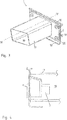
- FIG. 1 shows a receptacle 1 according to the invention for incorporation into a bumper arrangement not shown here.
- the receptacle 1 consists of a flange plate 2 and a hole element 3.
- the hole member 3 is formed as a threaded sleeve 4, wherein in the hole member 3, an internal thread 5 is located.
- the threaded sleeve 4 is coupled in a foot region 6 with the flange plate 2. This coupling takes place for example via a weld seam 7 shown here.
- the flange plate 2 itself has a stiffening bead 10 on an upper side 8 and a lower side 9.
- the stiffening beads 10 simultaneously serve the positive coupling possibility of a crash box not shown here.
- mounting holes 11 are still available, with which the flange plate 2 and thus the entire receptacle 1 between a crash box and a motor vehicle is einliederbar.
- FIG. 2 shows the recording according to FIG. 1 , wherein in addition a support member 12 and a receiving lug 13 are shown here.
- the receiving lug 13 serves to receive 1 components of a crash management system, not shown here in detail or else additional components and, for example, an exhaust muffler or an infrared sensor or similar components.
- the support member 12 itself has Abstweilflansche 14, 15, in which case three Abstweilflansche 14, 15 are visible.
- the lateral Abstweilflansche 14 are just formed and come to the flange plate 2 to the plant. These can be coupled to the flange plate 2, for example, via a weld, not shown here.
- the upper Abstützflansch 15 extends to the flange plate 2 executed broader.
- the corresponding drawn motor vehicle coordinate system shows that here not only forces in vehicle X-direction, but also in vehicle Y-direction are better absorbed.
- the support member 12 has an opening 16, wherein the hole member 3, the support member 12 in the opening 16 passes through.
- FIG. 3 shows the recording according to the invention with an attached crash box 17.
- the recording 1 itself is not shown here, but is partially integrated in an interior 18 of the crash box 17.
- the crash box 17 also has a crash box flange plate 19, wherein the crash box flange plate 19 is coupled to the flange plate 2 of the receptacle 1 via bolts 20.
- the crash box 17 itself is thus supported on the crash box flange plate 19 and on the flange plate 2 of the receptacle 1.
- the stiffening beads 10 also have a positive effect here on an increased moment of resistance against bending of the two flange plates 2.
- FIG. 4 shows a side cross-sectional view of FIG. 3 according to section line IV-V.
- the hole element 3 is arranged with support element 12 in the inner shell 18 of the crash box 17. Due to the small length of the hole element 3 with respect to the crash box 17, the folding property of the crash box 17 is not affected.
- a collar K is formed on the hole element 3, which is positively coupled to the flange plate 2.
- FIG. 5 shows a bumper assembly according to the invention with a cross member 21, a crash box 17 and a receptacle 1.
- the cross member 21 has a mounting opening 22 through which a towing eye, not shown here in the receptacle 1 can be inserted and screwed.
Landscapes
- Engineering & Computer Science (AREA)
- Transportation (AREA)
- Mechanical Engineering (AREA)
- Body Structure For Vehicles (AREA)
Applications Claiming Priority (1)
| Application Number | Priority Date | Filing Date | Title |
|---|---|---|---|
| DE102011010798A DE102011010798A1 (de) | 2011-02-09 | 2011-02-09 | Stoßfängeranordnung mit Abschleppvorrichtung |
Publications (2)
| Publication Number | Publication Date |
|---|---|
| EP2487055A1 true EP2487055A1 (fr) | 2012-08-15 |
| EP2487055B1 EP2487055B1 (fr) | 2016-04-20 |
Family
ID=45655429
Family Applications (1)
| Application Number | Title | Priority Date | Filing Date |
|---|---|---|---|
| EP12154397.9A Active EP2487055B1 (fr) | 2011-02-09 | 2012-02-08 | Agencement de pare-chocs doté d'un dispositif de remorquage |
Country Status (3)
| Country | Link |
|---|---|
| EP (1) | EP2487055B1 (fr) |
| DE (1) | DE102011010798A1 (fr) |
| ES (1) | ES2572503T3 (fr) |
Cited By (9)
| Publication number | Priority date | Publication date | Assignee | Title |
|---|---|---|---|---|
| US9908564B1 (en) | 2017-04-12 | 2018-03-06 | Nissan North America, Inc. | Vehicle body structure |
| GB2563594A (en) * | 2017-06-19 | 2018-12-26 | Jaguar Land Rover Ltd | Releasable connector for a vehicle |
| GB2567477A (en) * | 2017-10-13 | 2019-04-17 | Jaguar Land Rover Ltd | A tow-eye support |
| US10526017B2 (en) | 2018-04-30 | 2020-01-07 | Nissan North America, Inc. | Vehicle body structure |
| US10661833B2 (en) | 2018-06-29 | 2020-05-26 | Nissan North America, Inc. | Vehicle body structure |
| GB2582406A (en) * | 2017-06-19 | 2020-09-23 | Jaguar Land Rover Ltd | Releasable connector for a vehicle |
| CN111845225A (zh) * | 2020-07-23 | 2020-10-30 | 中通客车控股股份有限公司 | 一种客车拖车钩装置及一种客车 |
| US11407449B2 (en) | 2020-02-24 | 2022-08-09 | Nissan North America, Inc. | Energy absorbing structure for vehicle frame |
| GB2609946A (en) * | 2021-08-18 | 2023-02-22 | Jaguar Land Rover Ltd | Recovery hook mounting assembly |
Families Citing this family (6)
| Publication number | Priority date | Publication date | Assignee | Title |
|---|---|---|---|---|
| DE102014007781B3 (de) * | 2014-05-21 | 2015-07-09 | Audi Ag | Heckabschlussvorrichtung zur heckseitigen Montage an einer Fahrzeugkarosserie mit Heckklappe |
| DE102015113773B3 (de) * | 2015-08-19 | 2016-09-08 | Benteler Automobiltechnik Gmbh | Stoßfängeranordnung für ein Kraftfahrzeug |
| DE102018001611A1 (de) | 2018-03-01 | 2018-08-09 | Daimler Ag | Abschleppösenaufnahmevorrichtung für ein Kraftfahrzeug |
| DE102018106224B4 (de) | 2018-03-16 | 2023-02-23 | Benteler Automobiltechnik Gmbh | Stoßfängeranordnung für ein Kraftfahrzeug |
| DE102018107487A1 (de) * | 2018-03-28 | 2019-10-02 | Benteler Automobiltechnik Gmbh | Stoßfängeranordnung für ein Kraftfahrzeug |
| CN110962513A (zh) * | 2019-11-26 | 2020-04-07 | 奇瑞汽车股份有限公司 | 拖车钩螺母盒 |
Citations (6)
| Publication number | Priority date | Publication date | Assignee | Title |
|---|---|---|---|---|
| JP2003002136A (ja) * | 2001-06-21 | 2003-01-08 | Nissan Motor Co Ltd | 自動車の牽引フック取付構造 |
| FR2869263A1 (fr) * | 2004-04-22 | 2005-10-28 | Benteler Automobiltechnik Gmbh | Dispositif de fixation d'une unite de remorquage dans un support en aluminium travaillant en flexion d'un vehicule automobile |
| EP1721786A2 (fr) | 2005-05-13 | 2006-11-15 | Alcan Technology & Management Ltd. | Système de pare-chocs |
| DE102007024882A1 (de) * | 2007-05-29 | 2008-12-04 | GM Global Technology Operations, Inc., Detroit | Halter für die Abschleppöse eines Kraftfahrzeugs |
| DE202007018727U1 (de) * | 2007-12-18 | 2009-04-09 | Ise Automotive Gmbh | Abschleppbuchseneinheit |
| DE102010019551A1 (de) * | 2010-05-05 | 2010-12-16 | Daimler Ag | Energieabsorptionselement für einen Kraftwagen sowie Anordnung zweier solcher Energieabsorptionselemente |
Family Cites Families (2)
| Publication number | Priority date | Publication date | Assignee | Title |
|---|---|---|---|---|
| DE10110332A1 (de) * | 2001-03-03 | 2002-09-12 | Bayerische Motoren Werke Ag | Fahrzeug |
| JP4737768B2 (ja) * | 2006-08-04 | 2011-08-03 | 株式会社神戸製鋼所 | 脱着式牽引フックの取付構造 |
-
2011
- 2011-02-09 DE DE102011010798A patent/DE102011010798A1/de not_active Ceased
-
2012
- 2012-02-08 EP EP12154397.9A patent/EP2487055B1/fr active Active
- 2012-02-08 ES ES12154397T patent/ES2572503T3/es active Active
Patent Citations (6)
| Publication number | Priority date | Publication date | Assignee | Title |
|---|---|---|---|---|
| JP2003002136A (ja) * | 2001-06-21 | 2003-01-08 | Nissan Motor Co Ltd | 自動車の牽引フック取付構造 |
| FR2869263A1 (fr) * | 2004-04-22 | 2005-10-28 | Benteler Automobiltechnik Gmbh | Dispositif de fixation d'une unite de remorquage dans un support en aluminium travaillant en flexion d'un vehicule automobile |
| EP1721786A2 (fr) | 2005-05-13 | 2006-11-15 | Alcan Technology & Management Ltd. | Système de pare-chocs |
| DE102007024882A1 (de) * | 2007-05-29 | 2008-12-04 | GM Global Technology Operations, Inc., Detroit | Halter für die Abschleppöse eines Kraftfahrzeugs |
| DE202007018727U1 (de) * | 2007-12-18 | 2009-04-09 | Ise Automotive Gmbh | Abschleppbuchseneinheit |
| DE102010019551A1 (de) * | 2010-05-05 | 2010-12-16 | Daimler Ag | Energieabsorptionselement für einen Kraftwagen sowie Anordnung zweier solcher Energieabsorptionselemente |
Cited By (14)
| Publication number | Priority date | Publication date | Assignee | Title |
|---|---|---|---|---|
| US10150518B2 (en) | 2017-04-12 | 2018-12-11 | Nissan North America, Inc. | Vehicle body structure |
| US9908564B1 (en) | 2017-04-12 | 2018-03-06 | Nissan North America, Inc. | Vehicle body structure |
| GB2582406A (en) * | 2017-06-19 | 2020-09-23 | Jaguar Land Rover Ltd | Releasable connector for a vehicle |
| GB2563594A (en) * | 2017-06-19 | 2018-12-26 | Jaguar Land Rover Ltd | Releasable connector for a vehicle |
| GB2582406B (en) * | 2017-06-19 | 2021-01-13 | Jaguar Land Rover Ltd | Releasable connector for a vehicle |
| GB2563594B (en) * | 2017-06-19 | 2020-01-22 | Jaguar Land Rover Ltd | Releasable connector for a vehicle |
| GB2567477B (en) * | 2017-10-13 | 2020-11-18 | Jaguar Land Rover Ltd | A tow-eye support |
| GB2567477A (en) * | 2017-10-13 | 2019-04-17 | Jaguar Land Rover Ltd | A tow-eye support |
| US10526017B2 (en) | 2018-04-30 | 2020-01-07 | Nissan North America, Inc. | Vehicle body structure |
| US10661833B2 (en) | 2018-06-29 | 2020-05-26 | Nissan North America, Inc. | Vehicle body structure |
| US11407449B2 (en) | 2020-02-24 | 2022-08-09 | Nissan North America, Inc. | Energy absorbing structure for vehicle frame |
| CN111845225A (zh) * | 2020-07-23 | 2020-10-30 | 中通客车控股股份有限公司 | 一种客车拖车钩装置及一种客车 |
| GB2609946A (en) * | 2021-08-18 | 2023-02-22 | Jaguar Land Rover Ltd | Recovery hook mounting assembly |
| GB2609946B (en) * | 2021-08-18 | 2023-11-29 | Jaguar Land Rover Ltd | Recovery hook mounting assembly |
Also Published As
| Publication number | Publication date |
|---|---|
| DE102011010798A1 (de) | 2012-08-09 |
| EP2487055B1 (fr) | 2016-04-20 |
| ES2572503T3 (es) | 2016-05-31 |
Similar Documents
| Publication | Publication Date | Title |
|---|---|---|
| EP2487055B1 (fr) | Agencement de pare-chocs doté d'un dispositif de remorquage | |
| EP1690779B1 (fr) | Châssis auxiliaire pour véhicules automobiles | |
| DE102012217431B4 (de) | Motorträger mit Ablenkvorrichtung | |
| DE102009004827B4 (de) | Stoßfänger | |
| DE102011051481B4 (de) | Stoßfängeranordnung für ein Kraftfahrzeug | |
| DE102016004577B4 (de) | Tragrahmenstruktur zum Befestigen wenigstens eines Energiespeichers an einem Kraftfahrzeugrohbau | |
| DE102010054641B4 (de) | Stoßfängeranordnung sowie Verfahren zum Betreiben einer Stoßfängeranordnung in einen Crashfall | |
| DE202013104703U1 (de) | Schwerlastmodulfahrzeug | |
| DE102010050013A1 (de) | Stoßfängeranordnung für ein Kraftfahrzeug | |
| DE102010020304A1 (de) | Hilfsträger | |
| WO2011058152A1 (fr) | Agencement modulaire de pare-chocs pour un véhicule | |
| DE102016010353A1 (de) | Schutzeinrichtung für eine Personenkraftwagenkarosserie | |
| DE102021129280A1 (de) | Anhängerkupplungsanordnung für ein Kraftfahrzeug | |
| DE102013001668B4 (de) | Karosseriestruktur eines Kraftfahrzeugs und Kraftfahrzeug mit einer derartigen Karosseriestruktur | |
| WO2010069087A1 (fr) | Support flexible | |
| DE202017101524U1 (de) | Fahrzeugstossfängeranordnung | |
| EP1754652B1 (fr) | Câssis du véhicule pour une véhicule utilitaire. | |
| DE102013007263A1 (de) | Schutzeinrichtung für eine Vorbaustruktur eines Kraftwagensrohbaus | |
| EP3339107B1 (fr) | Protection contre l'encastrement à l'arrière pour un véhicule | |
| EP2096003B1 (fr) | Système de support | |
| DE102010001231B4 (de) | Struktureinrichtung für ein Fahrzeug | |
| DE102013107179A1 (de) | Stoßabsorptionsvorrichtung für ein Kraftfahrzeug | |
| DE102011113473A1 (de) | Stoßfängerquerträger | |
| DE102006057665B4 (de) | Rahmenartiger Achsträger für ein Kraftfahrzeug | |
| EP2983930B1 (fr) | Élément structural dans la zone avant d'une automobile |
Legal Events
| Date | Code | Title | Description |
|---|---|---|---|
| PUAI | Public reference made under article 153(3) epc to a published international application that has entered the european phase |
Free format text: ORIGINAL CODE: 0009012 |
|
| AK | Designated contracting states |
Kind code of ref document: A1 Designated state(s): AL AT BE BG CH CY CZ DE DK EE ES FI FR GB GR HR HU IE IS IT LI LT LU LV MC MK MT NL NO PL PT RO RS SE SI SK SM TR |
|
| AX | Request for extension of the european patent |
Extension state: BA ME |
|
| 17P | Request for examination filed |
Effective date: 20121030 |
|
| 17Q | First examination report despatched |
Effective date: 20141107 |
|
| GRAP | Despatch of communication of intention to grant a patent |
Free format text: ORIGINAL CODE: EPIDOSNIGR1 |
|
| INTG | Intention to grant announced |
Effective date: 20150824 |
|
| RAP1 | Party data changed (applicant data changed or rights of an application transferred) |
Owner name: BENTELER AUTOMOBILTECHNIK GMBH |
|
| GRAS | Grant fee paid |
Free format text: ORIGINAL CODE: EPIDOSNIGR3 |
|
| INTG | Intention to grant announced |
Effective date: 20160105 |
|
| GRAA | (expected) grant |
Free format text: ORIGINAL CODE: 0009210 |
|
| AK | Designated contracting states |
Kind code of ref document: B1 Designated state(s): AL AT BE BG CH CY CZ DE DK EE ES FI FR GB GR HR HU IE IS IT LI LT LU LV MC MK MT NL NO PL PT RO RS SE SI SK SM TR |
|
| REG | Reference to a national code |
Ref country code: GB Ref legal event code: FG4D Free format text: NOT ENGLISH |
|
| REG | Reference to a national code |
Ref country code: CH Ref legal event code: EP |
|
| REG | Reference to a national code |
Ref country code: AT Ref legal event code: REF Ref document number: 791998 Country of ref document: AT Kind code of ref document: T Effective date: 20160515 |
|
| REG | Reference to a national code |
Ref country code: IE Ref legal event code: FG4D Free format text: LANGUAGE OF EP DOCUMENT: GERMAN |
|
| REG | Reference to a national code |
Ref country code: ES Ref legal event code: FG2A Ref document number: 2572503 Country of ref document: ES Kind code of ref document: T3 Effective date: 20160531 |
|
| REG | Reference to a national code |
Ref country code: DE Ref legal event code: R096 Ref document number: 502012006768 Country of ref document: DE |
|
| REG | Reference to a national code |
Ref country code: LT Ref legal event code: MG4D |
|
| REG | Reference to a national code |
Ref country code: NL Ref legal event code: MP Effective date: 20160420 |
|
| PG25 | Lapsed in a contracting state [announced via postgrant information from national office to epo] |
Ref country code: PL Free format text: LAPSE BECAUSE OF FAILURE TO SUBMIT A TRANSLATION OF THE DESCRIPTION OR TO PAY THE FEE WITHIN THE PRESCRIBED TIME-LIMIT Effective date: 20160420 Ref country code: NO Free format text: LAPSE BECAUSE OF FAILURE TO SUBMIT A TRANSLATION OF THE DESCRIPTION OR TO PAY THE FEE WITHIN THE PRESCRIBED TIME-LIMIT Effective date: 20160720 Ref country code: FI Free format text: LAPSE BECAUSE OF FAILURE TO SUBMIT A TRANSLATION OF THE DESCRIPTION OR TO PAY THE FEE WITHIN THE PRESCRIBED TIME-LIMIT Effective date: 20160420 Ref country code: NL Free format text: LAPSE BECAUSE OF FAILURE TO SUBMIT A TRANSLATION OF THE DESCRIPTION OR TO PAY THE FEE WITHIN THE PRESCRIBED TIME-LIMIT Effective date: 20160420 Ref country code: LT Free format text: LAPSE BECAUSE OF FAILURE TO SUBMIT A TRANSLATION OF THE DESCRIPTION OR TO PAY THE FEE WITHIN THE PRESCRIBED TIME-LIMIT Effective date: 20160420 |
|
| PG25 | Lapsed in a contracting state [announced via postgrant information from national office to epo] |
Ref country code: RS Free format text: LAPSE BECAUSE OF FAILURE TO SUBMIT A TRANSLATION OF THE DESCRIPTION OR TO PAY THE FEE WITHIN THE PRESCRIBED TIME-LIMIT Effective date: 20160420 Ref country code: GR Free format text: LAPSE BECAUSE OF FAILURE TO SUBMIT A TRANSLATION OF THE DESCRIPTION OR TO PAY THE FEE WITHIN THE PRESCRIBED TIME-LIMIT Effective date: 20160721 Ref country code: LV Free format text: LAPSE BECAUSE OF FAILURE TO SUBMIT A TRANSLATION OF THE DESCRIPTION OR TO PAY THE FEE WITHIN THE PRESCRIBED TIME-LIMIT Effective date: 20160420 Ref country code: PT Free format text: LAPSE BECAUSE OF FAILURE TO SUBMIT A TRANSLATION OF THE DESCRIPTION OR TO PAY THE FEE WITHIN THE PRESCRIBED TIME-LIMIT Effective date: 20160822 Ref country code: HR Free format text: LAPSE BECAUSE OF FAILURE TO SUBMIT A TRANSLATION OF THE DESCRIPTION OR TO PAY THE FEE WITHIN THE PRESCRIBED TIME-LIMIT Effective date: 20160420 Ref country code: SE Free format text: LAPSE BECAUSE OF FAILURE TO SUBMIT A TRANSLATION OF THE DESCRIPTION OR TO PAY THE FEE WITHIN THE PRESCRIBED TIME-LIMIT Effective date: 20160420 |
|
| REG | Reference to a national code |
Ref country code: DE Ref legal event code: R097 Ref document number: 502012006768 Country of ref document: DE |
|
| PG25 | Lapsed in a contracting state [announced via postgrant information from national office to epo] |
Ref country code: RO Free format text: LAPSE BECAUSE OF FAILURE TO SUBMIT A TRANSLATION OF THE DESCRIPTION OR TO PAY THE FEE WITHIN THE PRESCRIBED TIME-LIMIT Effective date: 20160420 Ref country code: DK Free format text: LAPSE BECAUSE OF FAILURE TO SUBMIT A TRANSLATION OF THE DESCRIPTION OR TO PAY THE FEE WITHIN THE PRESCRIBED TIME-LIMIT Effective date: 20160420 Ref country code: CZ Free format text: LAPSE BECAUSE OF FAILURE TO SUBMIT A TRANSLATION OF THE DESCRIPTION OR TO PAY THE FEE WITHIN THE PRESCRIBED TIME-LIMIT Effective date: 20160420 Ref country code: EE Free format text: LAPSE BECAUSE OF FAILURE TO SUBMIT A TRANSLATION OF THE DESCRIPTION OR TO PAY THE FEE WITHIN THE PRESCRIBED TIME-LIMIT Effective date: 20160420 Ref country code: SK Free format text: LAPSE BECAUSE OF FAILURE TO SUBMIT A TRANSLATION OF THE DESCRIPTION OR TO PAY THE FEE WITHIN THE PRESCRIBED TIME-LIMIT Effective date: 20160420 |
|
| REG | Reference to a national code |
Ref country code: FR Ref legal event code: PLFP Year of fee payment: 6 |
|
| PLBE | No opposition filed within time limit |
Free format text: ORIGINAL CODE: 0009261 |
|
| STAA | Information on the status of an ep patent application or granted ep patent |
Free format text: STATUS: NO OPPOSITION FILED WITHIN TIME LIMIT |
|
| PG25 | Lapsed in a contracting state [announced via postgrant information from national office to epo] |
Ref country code: SM Free format text: LAPSE BECAUSE OF FAILURE TO SUBMIT A TRANSLATION OF THE DESCRIPTION OR TO PAY THE FEE WITHIN THE PRESCRIBED TIME-LIMIT Effective date: 20160420 |
|
| 26N | No opposition filed |
Effective date: 20170123 |
|
| PG25 | Lapsed in a contracting state [announced via postgrant information from national office to epo] |
Ref country code: SI Free format text: LAPSE BECAUSE OF FAILURE TO SUBMIT A TRANSLATION OF THE DESCRIPTION OR TO PAY THE FEE WITHIN THE PRESCRIBED TIME-LIMIT Effective date: 20160420 Ref country code: BE Free format text: LAPSE BECAUSE OF NON-PAYMENT OF DUE FEES Effective date: 20170228 |
|
| PG25 | Lapsed in a contracting state [announced via postgrant information from national office to epo] |
Ref country code: MC Free format text: LAPSE BECAUSE OF FAILURE TO SUBMIT A TRANSLATION OF THE DESCRIPTION OR TO PAY THE FEE WITHIN THE PRESCRIBED TIME-LIMIT Effective date: 20160420 |
|
| REG | Reference to a national code |
Ref country code: CH Ref legal event code: PL |
|
| PG25 | Lapsed in a contracting state [announced via postgrant information from national office to epo] |
Ref country code: LI Free format text: LAPSE BECAUSE OF NON-PAYMENT OF DUE FEES Effective date: 20170228 Ref country code: CH Free format text: LAPSE BECAUSE OF NON-PAYMENT OF DUE FEES Effective date: 20170228 |
|
| REG | Reference to a national code |
Ref country code: IE Ref legal event code: MM4A |
|
| PG25 | Lapsed in a contracting state [announced via postgrant information from national office to epo] |
Ref country code: LU Free format text: LAPSE BECAUSE OF NON-PAYMENT OF DUE FEES Effective date: 20170208 |
|
| REG | Reference to a national code |
Ref country code: BE Ref legal event code: MM Effective date: 20170228 |
|
| REG | Reference to a national code |
Ref country code: FR Ref legal event code: PLFP Year of fee payment: 7 |
|
| PG25 | Lapsed in a contracting state [announced via postgrant information from national office to epo] |
Ref country code: IE Free format text: LAPSE BECAUSE OF NON-PAYMENT OF DUE FEES Effective date: 20170208 |
|
| REG | Reference to a national code |
Ref country code: AT Ref legal event code: MM01 Ref document number: 791998 Country of ref document: AT Kind code of ref document: T Effective date: 20170208 |
|
| PG25 | Lapsed in a contracting state [announced via postgrant information from national office to epo] |
Ref country code: AT Free format text: LAPSE BECAUSE OF NON-PAYMENT OF DUE FEES Effective date: 20170208 |
|
| PG25 | Lapsed in a contracting state [announced via postgrant information from national office to epo] |
Ref country code: MT Free format text: LAPSE BECAUSE OF FAILURE TO SUBMIT A TRANSLATION OF THE DESCRIPTION OR TO PAY THE FEE WITHIN THE PRESCRIBED TIME-LIMIT Effective date: 20160420 |
|
| PG25 | Lapsed in a contracting state [announced via postgrant information from national office to epo] |
Ref country code: AL Free format text: LAPSE BECAUSE OF FAILURE TO SUBMIT A TRANSLATION OF THE DESCRIPTION OR TO PAY THE FEE WITHIN THE PRESCRIBED TIME-LIMIT Effective date: 20160420 |
|
| PG25 | Lapsed in a contracting state [announced via postgrant information from national office to epo] |
Ref country code: HU Free format text: LAPSE BECAUSE OF FAILURE TO SUBMIT A TRANSLATION OF THE DESCRIPTION OR TO PAY THE FEE WITHIN THE PRESCRIBED TIME-LIMIT; INVALID AB INITIO Effective date: 20120208 |
|
| PG25 | Lapsed in a contracting state [announced via postgrant information from national office to epo] |
Ref country code: BG Free format text: LAPSE BECAUSE OF FAILURE TO SUBMIT A TRANSLATION OF THE DESCRIPTION OR TO PAY THE FEE WITHIN THE PRESCRIBED TIME-LIMIT Effective date: 20160420 |
|
| PG25 | Lapsed in a contracting state [announced via postgrant information from national office to epo] |
Ref country code: CY Free format text: LAPSE BECAUSE OF NON-PAYMENT OF DUE FEES Effective date: 20160420 |
|
| PG25 | Lapsed in a contracting state [announced via postgrant information from national office to epo] |
Ref country code: MK Free format text: LAPSE BECAUSE OF FAILURE TO SUBMIT A TRANSLATION OF THE DESCRIPTION OR TO PAY THE FEE WITHIN THE PRESCRIBED TIME-LIMIT Effective date: 20160420 |
|
| PG25 | Lapsed in a contracting state [announced via postgrant information from national office to epo] |
Ref country code: TR Free format text: LAPSE BECAUSE OF FAILURE TO SUBMIT A TRANSLATION OF THE DESCRIPTION OR TO PAY THE FEE WITHIN THE PRESCRIBED TIME-LIMIT Effective date: 20160420 |
|
| PG25 | Lapsed in a contracting state [announced via postgrant information from national office to epo] |
Ref country code: IS Free format text: LAPSE BECAUSE OF FAILURE TO SUBMIT A TRANSLATION OF THE DESCRIPTION OR TO PAY THE FEE WITHIN THE PRESCRIBED TIME-LIMIT Effective date: 20160820 |
|
| PGFP | Annual fee paid to national office [announced via postgrant information from national office to epo] |
Ref country code: ES Payment date: 20250331 Year of fee payment: 14 |
|
| PGFP | Annual fee paid to national office [announced via postgrant information from national office to epo] |
Ref country code: GB Payment date: 20260219 Year of fee payment: 15 |
|
| PGFP | Annual fee paid to national office [announced via postgrant information from national office to epo] |
Ref country code: DE Payment date: 20260224 Year of fee payment: 15 |
|
| PGFP | Annual fee paid to national office [announced via postgrant information from national office to epo] |
Ref country code: IT Payment date: 20260224 Year of fee payment: 15 |
|
| PGFP | Annual fee paid to national office [announced via postgrant information from national office to epo] |
Ref country code: FR Payment date: 20260218 Year of fee payment: 15 |