EP2487103A1 - Appareil actionneur - Google Patents
Appareil actionneur Download PDFInfo
- Publication number
- EP2487103A1 EP2487103A1 EP11154289A EP11154289A EP2487103A1 EP 2487103 A1 EP2487103 A1 EP 2487103A1 EP 11154289 A EP11154289 A EP 11154289A EP 11154289 A EP11154289 A EP 11154289A EP 2487103 A1 EP2487103 A1 EP 2487103A1
- Authority
- EP
- European Patent Office
- Prior art keywords
- piston
- piston chamber
- pin
- pressure
- actuator member
- Prior art date
- Legal status (The legal status is an assumption and is not a legal conclusion. Google has not performed a legal analysis and makes no representation as to the accuracy of the status listed.)
- Ceased
Links
- XLYOFNOQVPJJNP-UHFFFAOYSA-N water Substances O XLYOFNOQVPJJNP-UHFFFAOYSA-N 0.000 claims abstract description 44
- 239000012530 fluid Substances 0.000 claims abstract description 9
- 239000000725 suspension Substances 0.000 claims description 6
- 230000005484 gravity Effects 0.000 claims description 3
- 230000004075 alteration Effects 0.000 description 1
- 230000000694 effects Effects 0.000 description 1
- 238000005265 energy consumption Methods 0.000 description 1
- 230000007613 environmental effect Effects 0.000 description 1
- 239000010720 hydraulic oil Substances 0.000 description 1
- 238000009434 installation Methods 0.000 description 1
- 238000012986 modification Methods 0.000 description 1
- 230000004048 modification Effects 0.000 description 1
- 239000013535 sea water Substances 0.000 description 1
Images



Classifications
-
- E—FIXED CONSTRUCTIONS
- E21—EARTH OR ROCK DRILLING; MINING
- E21B—EARTH OR ROCK DRILLING; OBTAINING OIL, GAS, WATER, SOLUBLE OR MELTABLE MATERIALS OR A SLURRY OF MINERALS FROM WELLS
- E21B41/00—Equipment or details not covered by groups E21B15/00 - E21B40/00
- E21B41/04—Manipulators for underwater operations, e.g. temporarily connected to well heads
-
- B—PERFORMING OPERATIONS; TRANSPORTING
- B63—SHIPS OR OTHER WATERBORNE VESSELS; RELATED EQUIPMENT
- B63C—LAUNCHING, HAULING-OUT, OR DRY-DOCKING OF VESSELS; LIFE-SAVING IN WATER; EQUIPMENT FOR DWELLING OR WORKING UNDER WATER; MEANS FOR SALVAGING OR SEARCHING FOR UNDERWATER OBJECTS
- B63C11/00—Equipment for dwelling or working underwater; Means for searching for underwater objects
- B63C11/52—Tools specially adapted for working underwater, not otherwise provided for
-
- F—MECHANICAL ENGINEERING; LIGHTING; HEATING; WEAPONS; BLASTING
- F16—ENGINEERING ELEMENTS AND UNITS; GENERAL MEASURES FOR PRODUCING AND MAINTAINING EFFECTIVE FUNCTIONING OF MACHINES OR INSTALLATIONS; THERMAL INSULATION IN GENERAL
- F16G—BELTS, CABLES, OR ROPES, PREDOMINANTLY USED FOR DRIVING PURPOSES; CHAINS; FITTINGS PREDOMINANTLY USED THEREFOR
- F16G15/00—Chain couplings, Shackles; Chain joints; Chain links; Chain bushes
-
- F—MECHANICAL ENGINEERING; LIGHTING; HEATING; WEAPONS; BLASTING
- F16—ENGINEERING ELEMENTS AND UNITS; GENERAL MEASURES FOR PRODUCING AND MAINTAINING EFFECTIVE FUNCTIONING OF MACHINES OR INSTALLATIONS; THERMAL INSULATION IN GENERAL
- F16G—BELTS, CABLES, OR ROPES, PREDOMINANTLY USED FOR DRIVING PURPOSES; CHAINS; FITTINGS PREDOMINANTLY USED THEREFOR
- F16G15/00—Chain couplings, Shackles; Chain joints; Chain links; Chain bushes
- F16G15/04—Quickly-detachable chain couplings; Shackles chain links with rapid junction means are classified according to the corresponding kind of chain
- F16G15/06—Shackles designed for attachment by joint pins to chain elements, e.g. D-shackles so called harp links; the D-chain links are classified according to the corresponding kind of chain
Definitions
- the present invention relates to a remotely operable actuator apparatus for underwater use and relates particularly, but not exclusively, to an actuator apparatus for underwater use operable by remotely operated vehicles (ROVs) or as a self contained unit operable by means of an acoustic trigger signal.
- ROVs remotely operated vehicles
- Preferred embodiments of the present invention seek to overcome this disadvantage of known apparatus.
- an actuator apparatus adapted to be remotely actuated underwater, the apparatus comprising:
- connector means adapted to connect at least one said piston chamber to at least one respective pressure source to create a pressure difference to cause the corresponding said piston member to move relative to the body at least partly under the action of pressure of the ambient water to cause the or each corresponding said actuator member to move from a first position thereof to a second position thereof, this provides the advantage that movement of the piston member can be carried out by a remotely operated vehicle, and greater power can be achieved than for apparatus in which the or each actuator member is directly driven by a remotely operated vehicle.
- the apparatus may further comprise at least one first pressure source adapted to have a lower pressure than the pressure in at least one said piston chamber prior to connection thereto.
- At least one said pressure source may comprise at least one respective gas container.
- This provides the advantage that for example by providing a container of air at lower pressure than the water pressure at the operating depth, the water in which the apparatus operates can be used to occupy the piston chamber, and entry of water into the fluid container can be used to create a pressure difference between the piston chamber and the ambient water.
- This provides the advantage of low energy consumption, by using the pressure generated by the ambient water, and reduces the risk of environmental damage if the apparatus should leak.
- At least one said piston member may be adapted to sealingly engage the body to define a respective first said piston chamber and a respective second said piston chamber, and said connector means may be adapted to connect at least one said first piston chamber and the cooperating said second piston chamber to respective first and second sources of pressure urging the corresponding said actuator member in opposite directions.
- the apparatus may further comprise locking means for locking at least one said piston member in position relative to the body.
- the connector means and/or said locking means may be remotely operable.
- the connector means and/or said locking means may be operable by means of a remotely operated vehicle (ROV).
- ROV remotely operated vehicle
- the connector means and/or said locking means may be acoustically operable.
- At least one said piston chamber may be adapted to contain water and to be in fluid communication with water surrounding the apparatus.
- At least one said actuator member may be a blade adapted to cut a cable, rope or pin.
- the apparatus may further comprise at least one suspension portion for enabling the apparatus to be suspended such that the suspension portion is substantially vertically above the centre of gravity of the apparatus when submerged.
- the apparatus may further comprise braking means for resisting movement of at least one said actuator member to said second position thereof.
- the braking means may comprise restrictor means for restricting flow of water out of at least one said piston chamber as a result of movement of at least one said actuator member from said first position thereof to said second position thereof.
- the braking means may comprise at least one respective extension member extending from at least one said actuator member through said body to contact the ambient water such that the ambient water in contact with the or each extension member urges the corresponding said actuator member towards said first position thereof.
- the body may further comprise at least one removable position through which at least one said actuator member extends in use.
- This provides the advantage of enabling the dimension, such as cross sectional area, of the actuator member to be chosen so as to provide a degree of resistance to movement of the corresponding actuator member appropriate to the water depth in which the apparatus is to be used.
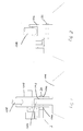
- an actuator apparatus 2 embodying the present invention is mounted to a shackle 1002 such that a pin 20 of the apparatus 2 extends through a pair of aligned apertures 1010 in the shackle 1002 and an aperture 1012 in a pad-eye 1004 of a structure 1006 in order to enable the structure 1006 to be lifted by means of a sling 1008 mounted to the shackle 1002.
- the apparatus 2 is mounted to the pad-eye 1004 of the structure 1006 such that the pin 20 extends through a connector 1014 to which the sling 1008 is mounted.
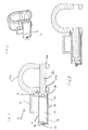
- the actuator apparatus 2 of a first embodiment of the present invention has a body 4 defining a grab handle 6 for engagement by a remotely operated vehicle (ROV) (not shown) and an attachment portion 8 for mounting the body 4 to the shackle 1002.
- the body 4 defines a piston cylinder 12 in which a piston 14 sealingly slides to define a first piston chamber 16 on one side of the piston 14 and a second piston chamber 18 on the other side of the piston 14.
- the piston 14 is formed on the end of a pin 20 which slides between a first position in which the pin 20 engages both apertures 1010 through the shackle 1002, and a second position in which the shackle 1002 can be removed from the structure 1006.
- the end of the pin 20 remote from the piston 14 is exposed to the ambient water in use so that the pin 20 is subjected to the pressure of the ambient water.
- the first 16 and second 18 piston chambers are connected via respective conduits 22, 24 to a hydraulic connector 26 to enable hydraulic fluid to be directed to the first piston chamber 16 or second piston chamber 18 from a pressure source such as an ROV pump (not shown) to create a pressure difference between the first 16 and second 18 piston chambers to cause the piston 14 to slide in the piston cylinder 12 under the action of the pressure of the ambient water at the end of the pin 20 remote from the piston 14.
- a pressure source such as an ROV pump (not shown) to create a pressure difference between the first 16 and second 18 piston chambers to cause the piston 14 to slide in the piston cylinder 12 under the action of the pressure of the ambient water at the end of the pin 20 remote from the piston 14.
- the apparatus 2 is mounted to the shackle 1002 by means of a standard interface at the connector portion 8, and suitable connectors such as bolts 28 are used to attach the apparatus 2 to the shackle 1002.
- the pin 20 is aligned with apertures 1010 in the shackle 1002 and a suitable pump (not shown) on the ROV drives hydraulic fluid, which may be hydraulic oil, seawater or any other type of fluid, into the second piston chamber 18 to create a pressure difference between the first 16 and second 18 piston chambers.
- the pressures on both sides of the piston 14 are initially equal to each other but the additional pressure generated by the ROV creates a pressure difference which causes the pin 20 to be retracted from the bore 30 to enable rigging hardware to be removed from the structure 1006, or hydraulic fluid is driven into the first piston chamber 16 to extend the pin 20 to locate it in the bore 30 to prevent removal of the rigging hardware from the structure 1006.
- a pressure source comprising a bottle 132 filled with air or other gas (typically at atmospheric pressure, but this could also be at the lowest pressure practicably possible) is selectively connected via a valve 134 to first piston chamber 116 to create a pressure difference between the first 116 and second 118 piston chambers to cause the pressure of the ambient water to move the pin 120 from the position shown in Figure 6 to the position shown in Figure 8 , and by using the valve 134, and applying suction on the other side of the piston, back again to the position shown in Figure 6 .
- air or other gas typically at atmospheric pressure, but this could also be at the lowest pressure practicably possible
- the valve 134 is actuated either mechanically by the ROV or acoustically, as a result of which the first piston chamber 116 is connected to the air bottle 132, which is at lower pressure than the second piston chamber 118.
- water can be driven into the bottle 132 as a result of which the piston 114 slides in the piston cylinder 112 to retract the pin 120 under the action of the ambient water.
- a hydraulic pressure source of an ROV can be connected via the valve 134 and conduits 122, 124 to the first 116 and second 118 piston chambers respectively to create a positive or negative pressure difference between the first and second piston chambers 116, 118 to extend or retract the pin 120 relative to the body 104.
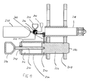
- a third embodiment of the present invention has a body 204 defining a single piston chamber 216 and a pin 220 is provided with grooves 240, 242 for engagement with a locking pin 244 to lock the pin 220 in an extended or retracted position.
- the single piston chamber 216 is connected via a conduit 222 and a valve 234 either to an outlet 246 in fluid communication with the ambient water or to an air filled bottle 232 at a pressure significantly lower than the pressure of the ambient water.
- the locking pin 244 and valve 234 are actuated by means of an acoustic actuator 248 or by ROV through handle 252.
- the components of the apparatus of Figure 9 are arranged such that when the apparatus is suspended, the centre of gravity is substantially below the suspension point when the apparatus is submerged in water so that the body 204 of the apparatus lies generally horizontally. This is achieved by arranging the acoustic actuator 248 in a central pipe of the shackle and locating the air filled bottle 232 on the same side of the suspension point as many of the components of the apparatus, so that the buoyancy of the air filled bottle 232 acts to at least partially counteract the weight of the components.
- the locking pin 244 is disengaged from the groove 240 in the pin 220 by means of the acoustic actuator 248.
- the piston chamber 216 and the end 250 of the pin 220 remote from the piston chamber 216 are connected via the conduit 222 to the ambient water, as a result of which the pin 220 is under pressure equilibrium and will remain stationary relative to the body 204.
- the valve 234 is then actuated by means of the acoustic actuator 248 to disconnect the piston chamber 216 from the ambient water and to connect it to the air filled bottle 232, which is at lower pressure than the pressure of the piston chamber 216. This causes a pressure difference between the piston chamber 216 and the ambient water, as a result of which the pin 220 is pushed into the piston chamber 216 under the action of the ambient water.
- an ROV (not shown) can also manually actuate the valve 234 by means of a first handle 252 or can pull the pin 220 into the piston chamber 216 by means of a second handle 254 when the piston chamber 216 is connected to the ambient water via the outlet 246.
- an ROV can be connected to outlet 246 such that its pump pumps water out of the first piston chamber 216 via conduit 222 in order to create a pressure difference between the first piston chamber 216 and the ambient water.
- the second handle 254 is mounted to the pin 220 by means of a removable shaft 270 slidably passing through a seal 272 in a removable end cap 274 mounted to the body 204.
- the handle 254 acts as a braking means for resisting motion of the pin 220 towards the end cap 274, since the ambient water acting on handle 254 and the ambient water acting on end face 250 of pin 220 urge the pin 220 in opposite directions relative to the body 204. This therefore reduces the speed with which pin 220 moves towards end cap 274 in the case of deep water, where pressure differences acting on the pin 220 can be very large.
- the rate of retardation of motion of pin 220 can be selected to be suitable for the particular depth of water in which the apparatus is to be used.
- piston 314 on the end of pin 320 slides in the body 304 to define first 316 and second 318 piston chambers, which are connected via respective conduits 322, 324 to a valve 334.
- a piston end position latch 360 engages the piston 314 to lock it in position relative to the body 304, and is released by means of acoustic actuator 348, or by a mechanical release when connected to connector 362, or manually operated by an ROV by turning valve 352.
- the valve 334 is actuable by means of the acoustic actuator 348 to connect air filled bottle to the first piston chamber 316 ( Figure 10 ) to enable the pin 320 to be retracted into the piston chamber 316, or to the second piston chamber 318 ( Figure 11 ) to enable the pin 320 to be urged to the right as shown in Figure 11 .
- hydraulic pumps of an ROV can be connected via ROV hydraulic connectors 362 to the first 316 and second 318 piston chambers and the valve 334 actuated by the ROV by means of a handle 352. This enables a positive or negative pressure difference to be created between the first 316 and second 318 piston chambers, so that the pin 320 can be extended out of or retracted into the body 304.
- an apparatus of a fifth embodiment of the present invention has a braking means for resisting movement of pin 420 towards end cap 474 of body 404, wherein the braking means is in the form of an enlarged inlet 480 to conduit 422 which cooperates with an annular enlargement 482 on the end of the pin 420 facing the end cap 474.
- the inlet 480 to conduit 422 is initially unobstructed.
- the pin 120 can be replaced by a blade for cutting cable by extension of the blade from the body of the apparatus.
Landscapes
- Engineering & Computer Science (AREA)
- General Engineering & Computer Science (AREA)
- Mechanical Engineering (AREA)
- Mining & Mineral Resources (AREA)
- Geology (AREA)
- Life Sciences & Earth Sciences (AREA)
- Fluid Mechanics (AREA)
- Physics & Mathematics (AREA)
- General Life Sciences & Earth Sciences (AREA)
- Geochemistry & Mineralogy (AREA)
- Environmental & Geological Engineering (AREA)
- Ocean & Marine Engineering (AREA)
- Actuator (AREA)
Priority Applications (1)
| Application Number | Priority Date | Filing Date | Title |
|---|---|---|---|
| EP11154289A EP2487103A1 (fr) | 2011-02-14 | 2011-02-14 | Appareil actionneur |
Applications Claiming Priority (1)
| Application Number | Priority Date | Filing Date | Title |
|---|---|---|---|
| EP11154289A EP2487103A1 (fr) | 2011-02-14 | 2011-02-14 | Appareil actionneur |
Publications (1)
| Publication Number | Publication Date |
|---|---|
| EP2487103A1 true EP2487103A1 (fr) | 2012-08-15 |
Family
ID=43922149
Family Applications (1)
| Application Number | Title | Priority Date | Filing Date |
|---|---|---|---|
| EP11154289A Ceased EP2487103A1 (fr) | 2011-02-14 | 2011-02-14 | Appareil actionneur |
Country Status (1)
| Country | Link |
|---|---|
| EP (1) | EP2487103A1 (fr) |
Cited By (5)
| Publication number | Priority date | Publication date | Assignee | Title |
|---|---|---|---|---|
| WO2013077740A1 (fr) | 2011-11-25 | 2013-05-30 | Skjold Lars | Manille sous-marine |
| FR3020852A1 (fr) * | 2014-05-12 | 2015-11-13 | Peugeot Citroen Automobiles Sa | Dispositif d'arrimage pour le levage d'outillage |
| WO2016207457A1 (fr) * | 2015-06-22 | 2016-12-29 | Gomez Bueno, Andres | Dispositif de levage d'équipements industriels |
| EP3348845A4 (fr) * | 2015-09-10 | 2019-04-10 | Kawasaki Jukogyo Kabushiki Kaisha | Actionneur sous-marin et submersible pourvu de celui-ci |
| WO2020111938A1 (fr) * | 2018-11-28 | 2020-06-04 | Ihc Holland Ie B.V. | Ensemble manille |
Citations (4)
| Publication number | Priority date | Publication date | Assignee | Title |
|---|---|---|---|---|
| GB2301860A (en) * | 1995-06-08 | 1996-12-18 | Balmoral Norge As | Hydraulic shackle |
| WO1998020257A1 (fr) * | 1996-11-07 | 1998-05-14 | Selantic Industrier A/S | Accumulateur inverse |
| WO2006055581A2 (fr) * | 2004-11-16 | 2006-05-26 | Oceaneering International, Inc. | Etrier et procede de retrait ou d'installation d'un etrier sous-marin au moyen d'un engin telecommande |
| US7614209B1 (en) * | 2008-08-26 | 2009-11-10 | J. Ray Mcdermott, S.A. | Mechanically releasable shackle pin |
-
2011
- 2011-02-14 EP EP11154289A patent/EP2487103A1/fr not_active Ceased
Patent Citations (4)
| Publication number | Priority date | Publication date | Assignee | Title |
|---|---|---|---|---|
| GB2301860A (en) * | 1995-06-08 | 1996-12-18 | Balmoral Norge As | Hydraulic shackle |
| WO1998020257A1 (fr) * | 1996-11-07 | 1998-05-14 | Selantic Industrier A/S | Accumulateur inverse |
| WO2006055581A2 (fr) * | 2004-11-16 | 2006-05-26 | Oceaneering International, Inc. | Etrier et procede de retrait ou d'installation d'un etrier sous-marin au moyen d'un engin telecommande |
| US7614209B1 (en) * | 2008-08-26 | 2009-11-10 | J. Ray Mcdermott, S.A. | Mechanically releasable shackle pin |
Cited By (11)
| Publication number | Priority date | Publication date | Assignee | Title |
|---|---|---|---|---|
| WO2013077740A1 (fr) | 2011-11-25 | 2013-05-30 | Skjold Lars | Manille sous-marine |
| US9109659B2 (en) | 2011-11-25 | 2015-08-18 | Lars Skjold | Underwater shackle |
| EP2783133A4 (fr) * | 2011-11-25 | 2015-09-16 | Lars Skjold | Manille sous-marine |
| FR3020852A1 (fr) * | 2014-05-12 | 2015-11-13 | Peugeot Citroen Automobiles Sa | Dispositif d'arrimage pour le levage d'outillage |
| WO2016207457A1 (fr) * | 2015-06-22 | 2016-12-29 | Gomez Bueno, Andres | Dispositif de levage d'équipements industriels |
| EP3348845A4 (fr) * | 2015-09-10 | 2019-04-10 | Kawasaki Jukogyo Kabushiki Kaisha | Actionneur sous-marin et submersible pourvu de celui-ci |
| AU2016319229B2 (en) * | 2015-09-10 | 2019-11-21 | Kawasaki Jukogyo Kabushiki Kaisha | Underwater actuator and underwater vehicle including the same |
| US10550866B2 (en) | 2015-09-10 | 2020-02-04 | Kawasaki Jukogyo Kabushiki Kaisha | Underwater actuator and underwater vehicle including the same |
| WO2020111938A1 (fr) * | 2018-11-28 | 2020-06-04 | Ihc Holland Ie B.V. | Ensemble manille |
| NL2022084B1 (en) * | 2018-11-28 | 2020-06-25 | Ihc Holland Ie Bv | A shackle assembly |
| CN113167359A (zh) * | 2018-11-28 | 2021-07-23 | Ihc荷兰Ie有限公司 | 钩环组件 |
Similar Documents
| Publication | Publication Date | Title |
|---|---|---|
| US6609533B2 (en) | Valve actuator and method | |
| EP2487103A1 (fr) | Appareil actionneur | |
| US8857175B2 (en) | Two-stage submersible actuators | |
| AU2011253743B2 (en) | Rechargeable system for subsea force generating device and method | |
| AU2011250766B2 (en) | System for lifting thrusters for providing maintenance to thrusters of floating vessels | |
| CN101537984B (zh) | 一种防管路爆裂的卷扬马达闭式液压系统及其控制方法 | |
| CN105620667B (zh) | 浮标释放装置 | |
| US20120055679A1 (en) | System and Method for Rescuing a Malfunctioning Subsea Blowout Preventer | |
| CN107054594A (zh) | 一种由深度触发的分离式液压抛载装置 | |
| CN110966472A (zh) | 一种水下软管安全脱离装置 | |
| CN111156220A (zh) | 一种深海无内置动力源应急往复剪缆装置 | |
| CN107253518A (zh) | 深海手动液压驱动式可弃压载装置 | |
| CN103723613B (zh) | 一种用于吊放水下航行器的远程脱钩装置 | |
| CN112412901B (zh) | 一种水下伺服油缸液压系统及其工作方法 | |
| CN111792517B (zh) | 水下气囊浮力打捞的重力脱钩装置 | |
| EP3049579B1 (fr) | Ancre à succion | |
| KR101641033B1 (ko) | 해양 선박의 선체에서 개구부를 폐쇄하는 폐쇄 커버, 및 호이스팅 챔버의 하부 부분으로의 접근을 용이하게 하는 방법 | |
| KR101611145B1 (ko) | 해양 선박에서의 스러스터 조립체 | |
| CN120379894B (zh) | 用于水下钻孔组件的可锁定凸缘 | |
| CN211738346U (zh) | 一种水下软管安全脱离装置 | |
| CN209143567U (zh) | 科考船绞车系统缆松弛补偿装置 | |
| CN102913512B (zh) | 一种液压锁紧机构 | |
| CN110217365B (zh) | 水下用载物装置 | |
| KR101455654B1 (ko) | 스러스터 캐니스터의 빌지 흡입 시스템 | |
| WO1998020257A1 (fr) | Accumulateur inverse |
Legal Events
| Date | Code | Title | Description |
|---|---|---|---|
| PUAI | Public reference made under article 153(3) epc to a published international application that has entered the european phase |
Free format text: ORIGINAL CODE: 0009012 |
|
| AK | Designated contracting states |
Kind code of ref document: A1 Designated state(s): AL AT BE BG CH CY CZ DE DK EE ES FI FR GB GR HR HU IE IS IT LI LT LU LV MC MK MT NL NO PL PT RO RS SE SI SK SM TR |
|
| AX | Request for extension of the european patent |
Extension state: BA ME |
|
| STAA | Information on the status of an ep patent application or granted ep patent |
Free format text: STATUS: THE APPLICATION HAS BEEN REFUSED |
|
| 18R | Application refused |
Effective date: 20120924 |