EP2487267A2 - Installation métallurgique - Google Patents
Installation métallurgique Download PDFInfo
- Publication number
- EP2487267A2 EP2487267A2 EP10822307A EP10822307A EP2487267A2 EP 2487267 A2 EP2487267 A2 EP 2487267A2 EP 10822307 A EP10822307 A EP 10822307A EP 10822307 A EP10822307 A EP 10822307A EP 2487267 A2 EP2487267 A2 EP 2487267A2
- Authority
- EP
- European Patent Office
- Prior art keywords
- lined
- platform
- metallurgical complex
- melting
- metal
- Prior art date
- Legal status (The legal status is an assumption and is not a legal conclusion. Google has not performed a legal analysis and makes no representation as to the accuracy of the status listed.)
- Withdrawn
Links
Images



Classifications
-
- C—CHEMISTRY; METALLURGY
- C21—METALLURGY OF IRON
- C21C—PROCESSING OF PIG-IRON, e.g. REFINING, MANUFACTURE OF WROUGHT-IRON OR STEEL; TREATMENT IN MOLTEN STATE OF FERROUS ALLOYS
- C21C5/00—Manufacture of carbon-steel, e.g. plain mild steel, medium carbon steel or cast steel or stainless steel
- C21C5/56—Manufacture of steel by other methods
- C21C5/562—Manufacture of steel by other methods starting from scrap
- C21C5/565—Preheating of scrap
-
- C—CHEMISTRY; METALLURGY
- C21—METALLURGY OF IRON
- C21C—PROCESSING OF PIG-IRON, e.g. REFINING, MANUFACTURE OF WROUGHT-IRON OR STEEL; TREATMENT IN MOLTEN STATE OF FERROUS ALLOYS
- C21C5/00—Manufacture of carbon-steel, e.g. plain mild steel, medium carbon steel or cast steel or stainless steel
- C21C5/52—Manufacture of steel in electric furnaces
-
- B—PERFORMING OPERATIONS; TRANSPORTING
- B22—CASTING; POWDER METALLURGY
- B22D—CASTING OF METALS; CASTING OF OTHER SUBSTANCES BY THE SAME PROCESSES OR DEVICES
- B22D11/00—Continuous casting of metals, i.e. casting in indefinite lengths
- B22D11/14—Plants for continuous casting
- B22D11/143—Plants for continuous casting for horizontal casting
-
- B—PERFORMING OPERATIONS; TRANSPORTING
- B22—CASTING; POWDER METALLURGY
- B22D—CASTING OF METALS; CASTING OF OTHER SUBSTANCES BY THE SAME PROCESSES OR DEVICES
- B22D41/00—Casting melt-holding vessels, e.g. ladles, tundishes, cups or the like
- B22D41/04—Casting melt-holding vessels, e.g. ladles, tundishes, cups or the like tiltable
-
- B—PERFORMING OPERATIONS; TRANSPORTING
- B22—CASTING; POWDER METALLURGY
- B22D—CASTING OF METALS; CASTING OF OTHER SUBSTANCES BY THE SAME PROCESSES OR DEVICES
- B22D41/00—Casting melt-holding vessels, e.g. ladles, tundishes, cups or the like
- B22D41/12—Travelling ladles or similar containers; Cars for ladles
-
- B—PERFORMING OPERATIONS; TRANSPORTING
- B22—CASTING; POWDER METALLURGY
- B22D—CASTING OF METALS; CASTING OF OTHER SUBSTANCES BY THE SAME PROCESSES OR DEVICES
- B22D41/00—Casting melt-holding vessels, e.g. ladles, tundishes, cups or the like
- B22D41/12—Travelling ladles or similar containers; Cars for ladles
- B22D41/13—Ladle turrets
-
- B—PERFORMING OPERATIONS; TRANSPORTING
- B22—CASTING; POWDER METALLURGY
- B22D—CASTING OF METALS; CASTING OF OTHER SUBSTANCES BY THE SAME PROCESSES OR DEVICES
- B22D47/00—Casting plants
-
- C—CHEMISTRY; METALLURGY
- C21—METALLURGY OF IRON
- C21C—PROCESSING OF PIG-IRON, e.g. REFINING, MANUFACTURE OF WROUGHT-IRON OR STEEL; TREATMENT IN MOLTEN STATE OF FERROUS ALLOYS
- C21C5/00—Manufacture of carbon-steel, e.g. plain mild steel, medium carbon steel or cast steel or stainless steel
- C21C5/28—Manufacture of steel in the converter
- C21C5/285—Plants therefor
-
- C—CHEMISTRY; METALLURGY
- C21—METALLURGY OF IRON
- C21C—PROCESSING OF PIG-IRON, e.g. REFINING, MANUFACTURE OF WROUGHT-IRON OR STEEL; TREATMENT IN MOLTEN STATE OF FERROUS ALLOYS
- C21C5/00—Manufacture of carbon-steel, e.g. plain mild steel, medium carbon steel or cast steel or stainless steel
- C21C5/52—Manufacture of steel in electric furnaces
- C21C5/5211—Manufacture of steel in electric furnaces in an alternating current [AC] electric arc furnace
- C21C5/5217—Manufacture of steel in electric furnaces in an alternating current [AC] electric arc furnace equipped with burners or devices for injecting gas, i.e. oxygen, or pulverulent materials into the furnace
-
- C—CHEMISTRY; METALLURGY
- C21—METALLURGY OF IRON
- C21C—PROCESSING OF PIG-IRON, e.g. REFINING, MANUFACTURE OF WROUGHT-IRON OR STEEL; TREATMENT IN MOLTEN STATE OF FERROUS ALLOYS
- C21C7/00—Treating molten ferrous alloys, e.g. steel, not covered by groups C21C1/00 - C21C5/00
-
- F—MECHANICAL ENGINEERING; LIGHTING; HEATING; WEAPONS; BLASTING
- F27—FURNACES; KILNS; OVENS; RETORTS
- F27B—FURNACES, KILNS, OVENS OR RETORTS IN GENERAL; OPEN SINTERING OR LIKE APPARATUS
- F27B3/00—Hearth-type furnaces, e.g. of reverberatory type; Electric arc furnaces ; Tank furnaces
- F27B3/08—Hearth-type furnaces, e.g. of reverberatory type; Electric arc furnaces ; Tank furnaces heated electrically, with or without any other source of heat
- F27B3/085—Arc furnaces
-
- F—MECHANICAL ENGINEERING; LIGHTING; HEATING; WEAPONS; BLASTING
- F27—FURNACES; KILNS; OVENS; RETORTS
- F27D—DETAILS OR ACCESSORIES OF FURNACES, KILNS, OVENS OR RETORTS, IN SO FAR AS THEY ARE OF KINDS OCCURRING IN MORE THAN ONE KIND OF FURNACE
- F27D99/00—Subject matter not provided for in other groups of this subclass
- F27D2099/0085—Accessories
- F27D2099/0098—Means for moving the furnace
-
- Y—GENERAL TAGGING OF NEW TECHNOLOGICAL DEVELOPMENTS; GENERAL TAGGING OF CROSS-SECTIONAL TECHNOLOGIES SPANNING OVER SEVERAL SECTIONS OF THE IPC; TECHNICAL SUBJECTS COVERED BY FORMER USPC CROSS-REFERENCE ART COLLECTIONS [XRACs] AND DIGESTS
- Y02—TECHNOLOGIES OR APPLICATIONS FOR MITIGATION OR ADAPTATION AGAINST CLIMATE CHANGE
- Y02P—CLIMATE CHANGE MITIGATION TECHNOLOGIES IN THE PRODUCTION OR PROCESSING OF GOODS
- Y02P10/00—Technologies related to metal processing
- Y02P10/20—Recycling
Definitions
- the invention relates to metallurgy and can be used in the technology of production of steel products starting from steel melting and ending with output of rolled stock.
- transportation facilities are also used, in particular, steel teeming ladle cars that complicate the organisation of the process in an automatic mode thus reducing the production capacity.
- the main disadvantage of the known plants is a significant loss of time and energy due to a long transportation path of the steel-teeming ladle between the electric furnace, the "furnace-ladle” machine, continuous casting machine (CCM) etc., an increase in the number of the working personnel servicing the bridge cranes, an increase of the danger at operation of transportation steel teeming ladles which are hanged up the hooks of the bridge cranes increase the cost of the main and auxiliary equipment due to applications of cranes and ladles, complexity in the organisation of the process in an automatic mode.
- the object of the claimed invention is to create a metallurgical complex allowing one to reduce loss of time and energy at work, to reduce the cost the equipment and personnel and to increase the reliability and safety of the whole complex.
- This object is attained by creating a metallurgical complex including melting furnace, an out-of-furnace metal processing unit and a casting station, installed on technological platforms capable of receiving and transferring the molten metal with subsequent casting, characterized in that it is provided with three technological platforms installed one over another, the middle platform being capable of rotating about the central axis and is also provided with three identical lined containers situated in three positions at an angle of 120 ° to each other, the top platform being provided with means for melting metal and means for processing the melt capable of rising and lowering and installed on two adjacent lined containers to form steelmaking arc furnace positions and a melt processing unit positions, respectively, the casting station being mounted on the bottom platform in the immediate vicinity of the third position with a third lined container disposed therein.
- the object of the invention is also attained due to the fact that the lined containers are capable of being inclined.
- the object of the invention is also attained due to the fact that the metallurgical complex is provided with means for preheating the fusion mixture to be installed on a lined container disposed in the third position, which can be made in the form of a gas burner.
- the gas burner can be mounted on the lined container cover disposed in the third position.
- the object of the invention is also attained due to the fact that the middle platform is installed on roller supports coupled to a rotary drive.
- the object of the invention is also attained due to the fact that the metallurgical complex is provided with a matching device to control the rotation of the middle platform and movement by the devices for melting metal and melt processing.
- the object of the invention is also attained due to the fact that the middle platform is made in the form of a ring, and metal melting and melt processing devices are made in the form of an electrode system and a lined dome.
- the metallurgical complex has three service levels and three working platforms.
- the top and platform 1 and a bottom platform 2 are stationary.
- the middle platform 3 is made in the form of a ring and is rotated by a drive (not shown) about the central axis 4.
- This platform 3 is supported by three trunnion stations 5 and provided with three horizontal movement stabilizers 6.
- Arranged on this platform 3 at an angle of 120° to each other are three lined containers 7, 8, 9 made capable of inclination.
- the container 9 is located in plan on the vertical C-C at the lower part of the circle ( Fig. 1 ), and the first (container 7) and the second (container 8) parts are disposed at an angle of 120° to the left and to the right of the vertical C-C respectively.
- Arranged on the top stationary platform 1 are two portal cranes 10 and 11 with mechanisms for lifting electrodes 12 and 13 and domes 14 and 15 and mechanisms to control the electrodes 12 and 13, two furnace transformers 16 and 17 with a system to supply electric power to the electrodes 12 and 13 ( Figs. 2-4 ).
- the entire volume of melt is poured from the lined container into a metal receiver 21 of a steel pouring station 22 of a horizontal continuous casting machine or a machine with a low casting radius which are installed on the bottom stationary platform 2 ( Figs. 2-4 ).
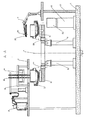
- Fig. 1 illustrates a layout of the main technological equipment of the metallurgical complex.
- the top platform 1 made in the form of a semicircle overlapping positions I and II supports the portal crane 10 of an arc steel melting furnace SMF, a portal crane 11 of the integrated steel processing plant (SPP), the furnace transformer 16, the SPP transformer 17.
- SMF arc steel melting furnace
- SPP integrated steel processing plant
- the platform 3 rests on three trunnion stations 5 and is made of modular steel structures ( Figs. 2-4 ). To reduce the weight of the platform, apertures are made therein.
- the platform is rotated by a mechanical drive (not shown in the drawing).
- the steel pouring station 22 of the horizontal continuous casting machine Arranged on the bottom platform 2 at the zero mark is the steel pouring station 22 of the horizontal continuous casting machine with a metal receiver 21 and a support 23 for the console crane 18.
- the metallurgical complex operates as follows. In the zero cycle ( Fig. 2 ) i.e. at the beginning of operation of the complex, the lined container 9 being in position III is charged with a fusion mixture, closed with the cover 19, and the gas burner 20 is switched on to preheat the fusion mixture. The containers 7 and 8 are not yet loaded. After the fusion mixture in the container 9 has been heated up to a preset temperature, the heating is stopped, the cover 19 with the burner 20 is lifted, and the lined container 9 is transferred to position I by turning the platform 3 around 120°. In so doing the containers 7 and 8 also move and take positions II and III.
- the container 9 is covered with the portal crane 10 hanged up on chains, the dome 14 and electrodes 12, the SMF power supply is switched on and the preheated fusion mixture is melting down ( Fig. 3 ). In so doing the container 7 in position II is not yet filled.
- the container 8 is moved to position III, loaded with a portion of the fusion mixture, the cover 19 is lowered and the gas burner 20 is switched on to heat the new portion of the fusion mixture in the container 8 ( Fig. 3 ). This takes place simultaneously with melting the first portion of the fusion mixture in position I of the container 9.
- the platform 3 is again turned around 120°. After that the containers 7, 8, 9 are moved to positions III, I, II respectively. Then the dome 14 with the electrodes 12 is again lowered in position I and close the container 8, the dome 15 with electrodes 13 is set in position II and close the container 9, and in position III the cover 19 with the burner 20 covers the container 7 preloaded with the fusion mixture.
- the power supply is connected to the SMF
- the SPP to the burner and the metal in a SMF is melted in position I
- the processing of the molten metal in the SPP is effected in position II
- the fusion mixture preheating is made in position III.
- the platform is turned through the following 120° and the container 9 with the first portion of metal processed in the SPP arrives, it is discharged into the metal receiver 21 of the pouring station 22 of the horizontal continuous casting machine for producing blanks.
- fusion mixture is loaded again and the following cycle of preheating is started in position III, the melting in position I, the metal processing in position II and the metal pouring with subsequent loading of the fusion mixture for preheating in position III.
- Fig.4 Illustrates the working moment of preheating the fusion mixture in the container 8 in position III and integrated processing of the molten metal in the container 7 in position II.
- the slag removal is made by draining the metal processed in position II through the apertures 24 into the slag cup installed on the bottom platform 1.
- the slag cup is driven away by a special tractor or in another way.
- the time of each cycle is calculated so that simultaneously with melting the fusion mixture in position I, the fusion mixture in position III would be already preheated to a required temperature, and the metal arrived at the SPP for processing would be already processed in position II. In this case all containers will be synchronously turned around for respective 120°. In so doing the time of pouring the metal, loading the fusion mixture and its preheating in position III strictly corresponds to the time of fusion and metal processing in positions I and II.
- the control the process of turning the platform 3 and lowering and rising the domes and covers is performed by a matching device associated with the system of automatic control of the preheating, melting and processing processes (not shown in the drawing).
- This device includes a mechanism for turning the platform 3 after a preset time and generates a signal on rising or lowering of the domes, switching on/off the power supply for carrying out the processes of preheating the fusion mixture and steel melting and processing in positions I, II, III.
- making the working platform 3 with a possibility of rotation provides transfer of the melting containers 7, 8, 9 under a cyclic schedule from one position to another through a certain time period during which a definite technological process is carried out in each container.
- the cycle time should correspond to the SMF operating time under load, the time of pouring of the molten steel from the container.
- the fusion mixture is preheating in one of the three containers.
- the fusion mixture is additionally heated, in position I the container performs the SMF function, in the third position II the container performs the SPP function.
- the volume of the melting containers is designed for loading a single charge and conducting the process without additional charging. The control is performed from a single control panel.
- this metallurgical complex Due to a compact design and availability of the rotating platform with melting containers, as well as due to a discharge of the whole melt into the metal receiver of the melting machine, this metallurgical complex has no need in steel-teeming ladles and bridge cranes.
Landscapes
- Engineering & Computer Science (AREA)
- Chemical & Material Sciences (AREA)
- Mechanical Engineering (AREA)
- Metallurgy (AREA)
- Organic Chemistry (AREA)
- Materials Engineering (AREA)
- Manufacturing & Machinery (AREA)
- General Engineering & Computer Science (AREA)
- Life Sciences & Earth Sciences (AREA)
- Botany (AREA)
- Vertical, Hearth, Or Arc Furnaces (AREA)
- Furnace Details (AREA)
- Refinement Of Pig-Iron, Manufacture Of Cast Iron, And Steel Manufacture Other Than In Revolving Furnaces (AREA)
Applications Claiming Priority (2)
| Application Number | Priority Date | Filing Date | Title |
|---|---|---|---|
| RU2009136947/02A RU2441074C2 (ru) | 2009-10-07 | 2009-10-07 | Металлургический комплекс |
| PCT/RU2010/000560 WO2011043699A2 (fr) | 2009-10-07 | 2010-10-06 | Installation métallurgique |
Publications (1)
| Publication Number | Publication Date |
|---|---|
| EP2487267A2 true EP2487267A2 (fr) | 2012-08-15 |
Family
ID=43857317
Family Applications (1)
| Application Number | Title | Priority Date | Filing Date |
|---|---|---|---|
| EP10822307A Withdrawn EP2487267A2 (fr) | 2009-10-07 | 2010-10-06 | Installation métallurgique |
Country Status (4)
| Country | Link |
|---|---|
| US (1) | US20120193062A1 (fr) |
| EP (1) | EP2487267A2 (fr) |
| RU (1) | RU2441074C2 (fr) |
| WO (1) | WO2011043699A2 (fr) |
Cited By (1)
| Publication number | Priority date | Publication date | Assignee | Title |
|---|---|---|---|---|
| CN105344991A (zh) * | 2015-12-08 | 2016-02-24 | 广西长城矿山机械设备制造有限公司 | 一种钢水包转移装置 |
Families Citing this family (3)
| Publication number | Priority date | Publication date | Assignee | Title |
|---|---|---|---|---|
| RU2502579C1 (ru) * | 2012-07-09 | 2013-12-27 | Анатолий Аркадьевич Злобин | Мобильный металлургический комплекс |
| CN107127331A (zh) * | 2016-02-29 | 2017-09-05 | 宝钢工程技术集团有限公司 | 钢包台车交替装置及其使用方法 |
| RU2705836C1 (ru) * | 2019-02-25 | 2019-11-12 | Максим Александрович Бирюков | Металлургический комплекс для производства стали |
Family Cites Families (5)
| Publication number | Priority date | Publication date | Assignee | Title |
|---|---|---|---|---|
| AT318678B (de) * | 1968-01-08 | 1974-11-11 | Huta Zabrze Fa | Vorrichtung zur Erzeugung von Metallegierungen, insbesondere von Stahllegierungen |
| RU1770373C (ru) * | 1990-03-23 | 1992-10-23 | Институт проблем литья АН УССР | Технологическа лини получени стали |
| RU15673U1 (ru) * | 2000-09-07 | 2000-11-10 | Закрытое акционерное общество "Патентные услуги" | Технологическая линия производства металлопроката |
| RU2285050C1 (ru) * | 2005-05-04 | 2006-10-10 | Открытое акционерное общество специального машиностроения и металлургии "Мотовилихинские заводы" | Способ и технологическая линия получения стали |
| RU84848U8 (ru) * | 2009-05-04 | 2010-02-10 | Закрытое акционерное общество "Патентные услуги" | Технологическая линия производства стали |
-
2009
- 2009-10-07 RU RU2009136947/02A patent/RU2441074C2/ru not_active IP Right Cessation
-
2010
- 2010-10-06 US US13/500,478 patent/US20120193062A1/en not_active Abandoned
- 2010-10-06 EP EP10822307A patent/EP2487267A2/fr not_active Withdrawn
- 2010-10-06 WO PCT/RU2010/000560 patent/WO2011043699A2/fr not_active Ceased
Non-Patent Citations (1)
| Title |
|---|
| See references of WO2011043699A2 * |
Cited By (1)
| Publication number | Priority date | Publication date | Assignee | Title |
|---|---|---|---|---|
| CN105344991A (zh) * | 2015-12-08 | 2016-02-24 | 广西长城矿山机械设备制造有限公司 | 一种钢水包转移装置 |
Also Published As
| Publication number | Publication date |
|---|---|
| RU2009136947A (ru) | 2011-04-20 |
| WO2011043699A3 (fr) | 2011-06-03 |
| RU2441074C2 (ru) | 2012-01-27 |
| US20120193062A1 (en) | 2012-08-02 |
| WO2011043699A2 (fr) | 2011-04-14 |
Similar Documents
| Publication | Publication Date | Title |
|---|---|---|
| CN101586908B (zh) | 冶金炉 | |
| EP0187861B1 (fr) | Appareil de prechauffage et de chargement de matieres premieres pour fourneau electrique | |
| US20120193062A1 (en) | Metallurgical complex | |
| US4502527A (en) | Single shop continuous casting facility | |
| US6521170B2 (en) | Revamping of a basic oxygen furnace installation to provide an electric furnace facility | |
| EP0219891B1 (fr) | Dispositif pour manipuler des poches de coulée | |
| US3610315A (en) | Continuous steelmaking system and process | |
| CN108486309A (zh) | 一种转炉炼钢系统及投加废钢和铁水的方法 | |
| CA2053912A1 (fr) | Installation metallurgique | |
| US4909303A (en) | Steel manufacturing system, particularly a mini-steel plant | |
| AU727804B2 (en) | Method to load scrap for electric arc furnace and relative system | |
| WO2004035837A1 (fr) | Transformation d'un convertisseur basique a oxygene en four electrique pour la production d'acier | |
| US4390168A (en) | Crane and hoist for steel manufacturing mill | |
| CN211546580U (zh) | 熔渣收送设备及熔渣处理系统 | |
| CN103502480B (zh) | 电熔炉 | |
| US5802098A (en) | Melting vessel with fastening, mounting and tilting devices | |
| CN210856207U (zh) | 液态金属精炼装置和液态金属冶炼系统 | |
| US3791636A (en) | Steel mill melt shop arrangement | |
| CN206616249U (zh) | 大型转炉炼钢设备组件 | |
| GB2270929A (en) | Continuous automatic steel making method and facility | |
| CN112176149A (zh) | 液态金属精炼装置、液态金属冶炼系统及精炼方法 | |
| WO2004036131A1 (fr) | Four electrique pour la production d'acier | |
| US6157664A (en) | System to load pre-heated scrap by means of baskets for electric arc furnace | |
| CN121344288A (zh) | 一种短流程电炉炼钢工艺布置方法 | |
| CN215697955U (zh) | 铁包车外固定位置加揭盖装置 |
Legal Events
| Date | Code | Title | Description |
|---|---|---|---|
| PUAI | Public reference made under article 153(3) epc to a published international application that has entered the european phase |
Free format text: ORIGINAL CODE: 0009012 |
|
| 17P | Request for examination filed |
Effective date: 20120504 |
|
| AK | Designated contracting states |
Kind code of ref document: A2 Designated state(s): AL AT BE BG CH CY CZ DE DK EE ES FI FR GB GR HR HU IE IS IT LI LT LU LV MC MK MT NL NO PL PT RO RS SE SI SK SM TR |
|
| DAX | Request for extension of the european patent (deleted) | ||
| STAA | Information on the status of an ep patent application or granted ep patent |
Free format text: STATUS: THE APPLICATION IS DEEMED TO BE WITHDRAWN |
|
| 18D | Application deemed to be withdrawn |
Effective date: 20130503 |