EP2487321A2 - Connecteur à fiches et raccord de tringlerie pour une tige de sondage - Google Patents
Connecteur à fiches et raccord de tringlerie pour une tige de sondage Download PDFInfo
- Publication number
- EP2487321A2 EP2487321A2 EP12000706A EP12000706A EP2487321A2 EP 2487321 A2 EP2487321 A2 EP 2487321A2 EP 12000706 A EP12000706 A EP 12000706A EP 12000706 A EP12000706 A EP 12000706A EP 2487321 A2 EP2487321 A2 EP 2487321A2
- Authority
- EP
- European Patent Office
- Prior art keywords
- rod assembly
- rod
- connection
- plug
- connector
- Prior art date
- Legal status (The legal status is an assumption and is not a legal conclusion. Google has not performed a legal analysis and makes no representation as to the accuracy of the status listed.)
- Granted
Links
Images


Classifications
-
- E—FIXED CONSTRUCTIONS
- E21—EARTH OR ROCK DRILLING; MINING
- E21B—EARTH OR ROCK DRILLING; OBTAINING OIL, GAS, WATER, SOLUBLE OR MELTABLE MATERIALS OR A SLURRY OF MINERALS FROM WELLS
- E21B7/00—Special methods or apparatus for drilling
- E21B7/002—Drilling with diversely driven shafts extending into the borehole
-
- E—FIXED CONSTRUCTIONS
- E21—EARTH OR ROCK DRILLING; MINING
- E21B—EARTH OR ROCK DRILLING; OBTAINING OIL, GAS, WATER, SOLUBLE OR MELTABLE MATERIALS OR A SLURRY OF MINERALS FROM WELLS
- E21B17/00—Drilling rods or pipes; Flexible drill strings; Kellies; Drill collars; Sucker rods; Cables; Casings; Tubings
- E21B17/02—Couplings; joints
- E21B17/04—Couplings; joints between rod or the like and bit or between rod and rod or the like
- E21B17/046—Couplings; joints between rod or the like and bit or between rod and rod or the like with ribs, pins, or jaws, and complementary grooves or the like, e.g. bayonet catches
-
- E—FIXED CONSTRUCTIONS
- E21—EARTH OR ROCK DRILLING; MINING
- E21B—EARTH OR ROCK DRILLING; OBTAINING OIL, GAS, WATER, SOLUBLE OR MELTABLE MATERIALS OR A SLURRY OF MINERALS FROM WELLS
- E21B17/00—Drilling rods or pipes; Flexible drill strings; Kellies; Drill collars; Sucker rods; Cables; Casings; Tubings
- E21B17/18—Pipes provided with plural fluid passages
-
- E—FIXED CONSTRUCTIONS
- E21—EARTH OR ROCK DRILLING; MINING
- E21B—EARTH OR ROCK DRILLING; OBTAINING OIL, GAS, WATER, SOLUBLE OR MELTABLE MATERIALS OR A SLURRY OF MINERALS FROM WELLS
- E21B21/00—Methods or apparatus for flushing boreholes, e.g. by use of exhaust air from motor
- E21B21/12—Methods or apparatus for flushing boreholes, e.g. by use of exhaust air from motor using drilling pipes with plural fluid passages, e.g. closed circulation systems
-
- E—FIXED CONSTRUCTIONS
- E21—EARTH OR ROCK DRILLING; MINING
- E21B—EARTH OR ROCK DRILLING; OBTAINING OIL, GAS, WATER, SOLUBLE OR MELTABLE MATERIALS OR A SLURRY OF MINERALS FROM WELLS
- E21B17/00—Drilling rods or pipes; Flexible drill strings; Kellies; Drill collars; Sucker rods; Cables; Casings; Tubings
- E21B17/02—Couplings; joints
- E21B17/028—Electrical or electro-magnetic connections
- E21B17/0285—Electrical or electro-magnetic connections characterised by electrically insulating elements
Definitions
- the invention relates to a connector for connecting two rod sections of a drill pipe and a corresponding rod section.
- a drill head When rod-based drilling in the ground, in particular for the production of so-called horizontal bores, which extend substantially parallel or at a relatively low inclination angle to the earth's surface, a drill head is driven by means of a drill string from a arranged on the earth's surface or in a pit drive device.
- the drill pipe used in this case consist of individual, interconnected rod sections, which - according to the course of drilling - gradually attached to the rear end of the already drilled drill string and connected to this. For this purpose usually threaded connections are used.
- Soft soil drilling is usually based on radial displacement and compaction of the soil.
- the drill head is therefore - if ever - regularly only - in addition to the static feed - driven at low speed rotating.
- a first of these designs relies on the use of an in-hole motor that rotates the drill head directly rather than rotating about the drill string. Rather, the unit of drill head and in-hole motor is fixed to the front of the drill pipe, via which the required axial pressure is applied to drive the bore. Since the drilling required for the drilling of the drill head is generated by the in-hole motor, it is not necessary in such drilling devices to drive the drill pipe itself rotating. The wear of the drill string is therefore relatively low.
- so-called "mud motors" are regularly used, in which a drive fluid is passed under high pressure through a turbine in order to effect the rotation.
- This propulsion fluid is usually a drilling fluid which, after passing through the mud engine, exits through holes in the area of the drill head into the bore to cool and lubricate the drill head and around the cleared cuttings over the annulus between the borehole wall and the drill pipe.
- Significant drawbacks of such in-hole engine based rock drilling rigs are the high drilling fluid consumption coupled with low performance (e.g., 800Nm with a purge fluid consumption of 320L / min).
- the second common design for rock drilling equipment is based on the use of a double drill pipe.
- the drill head is additionally rotationally driven via an inner linkage of the double drill pipe from the drive device arranged on the earth's surface or in an excavation, which also provides for the advance of the drill head.
- the inner rod is rotatably mounted within an outer linkage of the DoppelbohrgestCodes.
- the outer linkage therefore either does not have to be rotated at all or only at a low speed. Even with such rock drilling device, the wear of the drill string is limited, because the standing in contact with the rocky bore wall outer linkage does not rotate or only at low speed, while the driven at a high speed inner linkage can be mounted wear-reducing in the outer rod.
- the present invention seeks to provide an improved connector for a drill pipe and in particular for the inner rod of a Doppelbohrgestfites.
- the invention is based on the idea of specifying a way to connect two rod sections of a drill pipe, the advantages of the Known prior art threaded connections and the Axialsteckitatien combined.
- a connector which - similar to a threaded connection - based on helical on a cross-sectionally circular threaded connector or in a corresponding threaded bushing projections / grooves, wherein the projections / grooves are designed so that the characteristic of a threaded connection Self-locking does not occur.
- a plug-in connection according to the invention for connecting two rod sections of a drill string accordingly has a connection plug at one end of a first of the rod sections and a connection socket at one end of the second of the rod sections, wherein the connection plug and the connection socket are characterized in that each at least one (n) having spirally extending (n) guide projection and / or guide groove which engage in the joining of the connector.
- the guide In order to avoid a self-locking of the guide, it is preferably provided to carry out the spiral course with a very large pitch, preferably in the range of 15 ° to 25 ° relative to the longitudinal axis.
- the contact surfaces, over which the guide projections or guide grooves of the connector plug or the connecting sleeve abut each other, are largely aligned radially, i. a straight line laid on the contact surface in a direction perpendicular to the longitudinal axis of the plug-in connection at a (random) point points essentially in the direction of this longitudinal axis.
- the jamming of the thread flanks which is known from most threaded connections, can be avoided by a radial deformation of the connecting parts as a result of radial force components caused by the geometry of the thread flanks.
- the guide projections In a cross section selected perpendicular to the longitudinal axis of the plug connection, the guide projections preferably have a rectangular or trapezoidal cross section.
- the essential design criterion is preferably the pitch of the helical course of the guide projections / guide grooves, which are preferably chosen to be so large is that - even when using usual for drill pipe materials, especially steel, and achievable without significant post-processing of the contact surface surface quality - the connector according to the invention can also be joined exclusively by the application of compressive forces (which of course associated with a relative rotation of the two connecting parts is).
- a connector according to the invention but also always be joined by the exclusive application of torque, since the relative axial displacement is then - as in a threaded connection - forced by the spiral guide projections / guide grooves.
- the main advantages of the connector according to the invention are that it simply - like the already known Axialsteckitati - by the application of only axial forces (compressive or tensile forces in the direction of the longitudinal axis of the connector) joined and - because of the lack of self-locking - again (if necessary manually) can be solved.
- the use of a mechanical release device, as required for screw, can therefore be omitted.
- the helical formation of the guide projections / guide grooves causes the connectors to fix automatically as long as a torque (in the joining direction) is transmitted via the drill pipe.
- a secure cohesion of the individual rod sections of the drill string can be achieved when acting on these tensile forces, for example when retracting the drill string.
- the connector plug and / or the connection socket has a conical insertion section, by which a lack of coaxiality of the two connection parts is corrected during mating.
- a mechanical mating of the connecting parts of the connector according to the invention can be simplified.
- a seal can be provided which seals a ring space formed between the connection plug and the connection socket in the assembled state of the plug connection.
- a seal can avoid contamination of the contact surfaces of the connecting parts, for example by a drilling fluid entering through the annular space.
- An inventive rod assembly for a drill string has a rod end body, the two ends each comprise a connecting part of a connector according to the invention. Accordingly, the rod assembly main body at a (longitudinal axial) end of a connector of an inventive Plug connection and at the corresponding other end a connection socket of a plug connection according to the invention.
- Such a rod assembly according to the invention can preferably be used as an inner rod assembly of a double rod assembly according to the invention for a double drill rod, wherein the double rod assembly additionally comprises an outer rod assembly which surrounds the inner rod assembly.
- the rod assembly according to the invention may further comprise at least one cylindrical bearing seat for receiving a bearing ring.
- This bearing seat can preferably receive a rotary bearing over which the rod assembly according to the invention, if this is provided as mecanicgestfiteschuss a double rod section, is mounted in the outer rod assembly.
- annular space can be provided, which can be preferably used for the transport of a drilling fluid.
- This annular space is at least partially closed by the rotary bearing, whereby the transport of the drilling fluid can be hindered.
- the bearing seat of the (inner) linkage of the invention is traversed by at least one channel (in the longitudinal axial direction).
- This signal line section can be, for example, an (electrically insulated) cable.
- an electrically conductive (kink-resistant) rod is suitable, provided that it is electrically insulated from the rod end body, the connector and the connector socket.
- the two ends of the signal line are also provided with a coupling part which allows a connection with a corresponding connection part of a signal line section of a second linkage to be connected to the first linkage.
- these coupling parts are designed as Axialsteckitati, so that they can be connected to each other automatically when connecting the two rod sections.
- the signal line should be axially supported at least in the region of the coupling parts in the rod section.
- connection of the outer rod sections of two double-rod sections according to the invention to be connected takes place via a screw connection, for which purpose each outer rod section has a threaded connector at one of the (longitudinal-axial) ends and a corresponding threaded socket at the other end.
- a screw connection for which purpose each outer rod section has a threaded connector at one of the (longitudinal-axial) ends and a corresponding threaded socket at the other end.
- the Fig. 1 shows in cross-section two interconnected ends of double linkage sections 1 according to the invention a DoppelbohrgestShes.
- Each of the double rod sections 1 comprises an outer linkage 2 and an inner linkage 3 arranged centrally therein.
- Each of the outer rod sections 2 is provided at one of its ends with a conical external thread and at the opposite end with a corresponding conical internal thread to form a threaded connection 4. About these threaded parts, the individual outer rod sections 2 are screwed together. The concrete form of this used for use thread and this thread having sections of the rod sections is in the DE 10 2008 047 060 A1 described.
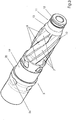
- each of the inner rod sections 3 at one of his Ends a connector 5, which is provided with helically extending guide projections 6 (see. Fig. 3 ), between which correspondingly shaped guide grooves 7 are formed.
- the guide projections 6 of the connector 5 cooperate in the mated state of the connector with the corresponding guide projections 8 a connecting sleeve 9 of the adjacent réellegestlindeschusses together, ie they engage in the guide grooves formed by these. Due to the helical course of the guide projections 6, 8, the mating movement combines both an axial relative displacement and a relative rotation of the two connecting parts (connecting plug 5 and connecting bush 9) to each other.
- the course of the spiral guide projections 6, 8 is provided with a very large pitch.
- each of the guide projections 6, 8 over the entire length of the guide projections receiving portion of the connector or the connecting sleeve winds around only about 70 ° about the longitudinal axis.
- the guide projections 6, 8 would thus - have a rectangular cross section - without the twist caused by the spiral course.
- these design features large slope, radial orientation of the contact surfaces 10
- the connector 5 is frontally provided with a reduced diameter in its insertion section 11 by having a smaller outer diameter than the remaining portions of the inner rod.
- the insertion section 11 of the connector is also provided with two conical sections 12, 13. In conjunction with a conical insertion section 14 of the connecting bushing 9 can be achieved by the insertion section 11 of the connector 5 a secure mating of the connector even if the two connecting parts are not recognized in exactly coaxial alignment with each other.
- the psychologygestfiteschadore 3 are hollow and thus formed as RohrgestCodeschadore.
- a signal line section 15 formed from a solid (metal) wire is arranged centrally and held in this position (also in the axial direction) via bearings (not shown) which are designed to be electrically insulating.
- Each of these signal line sections 15 has at one of its ends a plug 16 and at the corresponding other a socket 17 for forming an axial plug connection.
- Each of the inner rod sections 3 is rotatably supported by a sliding bearing ring 18 in the corresponding outer rod section 2.
- each of the inner rod sections 3 in the region of the connector 5 has a cylindrical bearing surface 19 for receiving an inner ring of the sliding bearing ring 18.
- the bearing surface 19 is limited to one side by a shoulder 20, which serves as an axial stop for the sliding bearing ring 18.
- the slide bearing ring 18 is connected by shrinking with the mecanicgestlindeschuss 3 (non-positively).
- the inside of each of the outer rod sections 2 has a corresponding bearing surface, which is in contact with an outer ring of the sliding bearing ring 18. Also, this bearing surface is bounded on one side by a shoulder 21, which in turn serves as (first) axial stop for the sliding bearing ring 18.
- a second axial stop is formed by a snap ring 22, which engages in a corresponding groove on the inside of the outer rod section 2.
- the bearing of the sliding bearing ring 18 in the outer rod assembly 2 takes place with play, so that a simple assembly and disassembly (for example, for maintenance purposes) of the sliding bearing ring 18 and the associated mecanicestlindeschusses 3 is possible.
- only the snap ring 22 has to be removed and the (only via the one slide bearing ring mounted) réellegestfiteschuss 3 are pulled out of the outer linkage 2.
- annular space 23 is formed, through which a drilling fluid is to be transported.
- this annular space 23 is (at least partially) blocked, so that a total of three channels 24 are provided for the transport of the drilling fluid, which are integrated into the wall of the réellegestfiteschusses 2 and the bearing surface 19 and thus under the slide bearing ring 18 in the longitudinal axial direction, as can be seen in particular from Fig. 2 and 3 results.
- the threaded connections and the connectors of the inner linkage each with a seal 26, 27 provided in the form of commercially available O-rings, which is positioned in corresponding grooves of the threaded or connector plug 5.
Landscapes
- Engineering & Computer Science (AREA)
- Life Sciences & Earth Sciences (AREA)
- Geology (AREA)
- Mining & Mineral Resources (AREA)
- Physics & Mathematics (AREA)
- Environmental & Geological Engineering (AREA)
- Fluid Mechanics (AREA)
- General Life Sciences & Earth Sciences (AREA)
- Geochemistry & Mineralogy (AREA)
- Mechanical Engineering (AREA)
- Earth Drilling (AREA)
Applications Claiming Priority (1)
| Application Number | Priority Date | Filing Date | Title |
|---|---|---|---|
| DE102011010958A DE102011010958A1 (de) | 2011-02-10 | 2011-02-10 | Steckverbindung und Gestängeschuss für Bohrgestänge |
Publications (3)
| Publication Number | Publication Date |
|---|---|
| EP2487321A2 true EP2487321A2 (fr) | 2012-08-15 |
| EP2487321A3 EP2487321A3 (fr) | 2016-04-06 |
| EP2487321B1 EP2487321B1 (fr) | 2018-11-21 |
Family
ID=45606946
Family Applications (1)
| Application Number | Title | Priority Date | Filing Date |
|---|---|---|---|
| EP12000706.7A Active EP2487321B1 (fr) | 2011-02-10 | 2012-02-02 | Connecteur à fiches et raccord de tringlerie pour une tige de sondage |
Country Status (3)
| Country | Link |
|---|---|
| US (1) | US9290992B2 (fr) |
| EP (1) | EP2487321B1 (fr) |
| DE (1) | DE102011010958A1 (fr) |
Families Citing this family (14)
| Publication number | Priority date | Publication date | Assignee | Title |
|---|---|---|---|---|
| USD721425S1 (en) * | 2013-01-28 | 2015-01-20 | E-Value LLC | Flexible tubing |
| DE102014018102A1 (de) * | 2014-12-05 | 2016-06-09 | Tracto-Technik Gmbh & Co. Kg | "Bohrgestänge, Verbindungssystem, Erdbohrvorrichtung und Verfahren zum Verbinden eines Bohrgestängeschusses" |
| CA3115307C (fr) * | 2017-05-01 | 2022-10-11 | U-Target Energy Ltd. | Generateur pour systeme de telemetrie en fond de trou |
| DE102018004951A1 (de) | 2018-06-22 | 2019-12-24 | Tracto-Technik Gmbh & Co. Kg | Verbindung zweier Bohrstrangglieder eines Bohrstrangs zum Erdbohren |
| DE102018008533A1 (de) | 2018-10-31 | 2020-04-30 | Tracto-Technik Gmbh & Co. Kg | Gestängeschuss eines Erdbohrgestänges |
| US11274549B2 (en) | 2020-03-18 | 2022-03-15 | Saudi Arabian Oil Company | Logging operations in oil and gas applications |
| US11286725B2 (en) * | 2020-03-18 | 2022-03-29 | Saudi Arabian Oil Company | Drill pipe segments for logging operations |
| DE102020005727A1 (de) | 2020-09-18 | 2022-03-24 | Tracto-Technik Gmbh & Co. Kg | Gestängeschuss eines Erdbohrgestänges |
| DE102020005982A1 (de) | 2020-09-30 | 2022-03-31 | Tracto-Technik Gmbh & Co. Kg | Gestängeschuss eines Erdbohrgestänges, Antriebselement, Gestängeschusssystem und Erdbohrvorrichtung |
| EP4086426B1 (fr) | 2021-05-03 | 2026-02-11 | TRACTO-TECHNIK GmbH & Co. KG | Accouplement de tiges d'une tige de tarière |
| WO2023017481A1 (fr) * | 2021-08-13 | 2023-02-16 | Gradidge, Robert Charles | Raccord d'acier de forage, tige et maîtresse-tige les comprenant |
| US11905791B2 (en) | 2021-08-18 | 2024-02-20 | Saudi Arabian Oil Company | Float valve for drilling and workover operations |
| US11913298B2 (en) | 2021-10-25 | 2024-02-27 | Saudi Arabian Oil Company | Downhole milling system |
| US12276190B2 (en) | 2022-02-16 | 2025-04-15 | Saudi Arabian Oil Company | Ultrasonic flow check systems for wellbores |
Citations (2)
| Publication number | Priority date | Publication date | Assignee | Title |
|---|---|---|---|---|
| EP0817901B1 (fr) | 1996-02-14 | 2004-04-21 | The Charles Machine Works Inc | Raccord de tuyaux a deux elements, destine a un train de tiges a deux elements |
| DE102008047060A1 (de) | 2008-09-12 | 2010-03-18 | Tracto-Technik Gmbh & Co. Kg | Gewindeverbindung |
Family Cites Families (12)
| Publication number | Priority date | Publication date | Assignee | Title |
|---|---|---|---|---|
| US2257101A (en) * | 1939-06-30 | 1941-09-30 | Boynton Alexander | Threadless drill pipe |
| US2280786A (en) * | 1939-07-17 | 1942-04-28 | Boynton Alexander | Threadless drill pipe |
| US2275418A (en) * | 1939-07-17 | 1942-03-10 | Boynton Alexander | Threadless drill pipe |
| US2551995A (en) * | 1948-01-30 | 1951-05-08 | Cicero C Brown | Rotary core drill with jar mechanism |
| DE1076596B (de) * | 1958-02-24 | 1960-03-03 | Kenneth Edward Waggener | Loesbare Sicherheitsverbindung fuer Tiefbohrstraenge |
| US4280535A (en) * | 1978-01-25 | 1981-07-28 | Walker-Neer Mfg. Co., Inc. | Inner tube assembly for dual conduit drill pipe |
| US4454922A (en) * | 1982-05-27 | 1984-06-19 | Consolidation Coal Company | Drill rod and drilling apparatus |
| CA2499760C (fr) * | 2002-08-21 | 2010-02-02 | Presssol Ltd. | Forage horizontal et directionnel a circulation inverse au moyen de tube de production spirale |
| US7084782B2 (en) * | 2002-12-23 | 2006-08-01 | Halliburton Energy Services, Inc. | Drill string telemetry system and method |
| CN103343669A (zh) * | 2006-05-24 | 2013-10-09 | 维米尔制造公司 | 具有改进的流动通道的方法和装置的双杆钻管 |
| US20100260540A1 (en) * | 2009-04-13 | 2010-10-14 | Church Kris L | Connection System for Tubular Members |
| DE102009035277B4 (de) | 2009-07-29 | 2023-10-26 | Tracto-Technik Gmbh & Co. Kg | Bohrvorrichtung |
-
2011
- 2011-02-10 DE DE102011010958A patent/DE102011010958A1/de not_active Withdrawn
-
2012
- 2012-02-02 EP EP12000706.7A patent/EP2487321B1/fr active Active
- 2012-02-09 US US13/369,791 patent/US9290992B2/en active Active
Patent Citations (2)
| Publication number | Priority date | Publication date | Assignee | Title |
|---|---|---|---|---|
| EP0817901B1 (fr) | 1996-02-14 | 2004-04-21 | The Charles Machine Works Inc | Raccord de tuyaux a deux elements, destine a un train de tiges a deux elements |
| DE102008047060A1 (de) | 2008-09-12 | 2010-03-18 | Tracto-Technik Gmbh & Co. Kg | Gewindeverbindung |
Also Published As
| Publication number | Publication date |
|---|---|
| EP2487321B1 (fr) | 2018-11-21 |
| US20120205908A1 (en) | 2012-08-16 |
| US9290992B2 (en) | 2016-03-22 |
| DE102011010958A1 (de) | 2012-08-16 |
| EP2487321A3 (fr) | 2016-04-06 |
Similar Documents
| Publication | Publication Date | Title |
|---|---|---|
| EP2487321B1 (fr) | Connecteur à fiches et raccord de tringlerie pour une tige de sondage | |
| EP2957710B1 (fr) | Tête de forage et dispositif de production d'un forage dans la terre | |
| EP2495389B1 (fr) | Tiges de forage | |
| DE102010027544A1 (de) | Verfahren zur Herstellung der Bohrvorrichtungen vor allem für die Rohrschirmtechnik und Bohrvorrichtung | |
| EP2737159B1 (fr) | Manchon porte-outil recevant des outils de forage tubulaires présentant de différents diamètres | |
| DE102012025187A1 (de) | Verbindungsvorrichtung | |
| DE102008006236A1 (de) | Injektionskopf für Injektionsbohranker | |
| DE102011109001A1 (de) | Bohrgerät mit Kelly-Stange und äußere Werkzeugschnellbefestigung | |
| EP0825326A2 (fr) | Procédé et dispositif pour le forage horizontal et pour la manipulation de tiges de forage | |
| EP1682745B1 (fr) | Procede et dispositif permettant de creuser des trous dans des sols ou des roches | |
| DE102011109330B4 (de) | Steuerbare Bohrvorrichtung | |
| EP3868998B1 (fr) | Raccordement de deux membres de tige de forage d'une tige de forage destiné au forage du sol | |
| DE102011122143A1 (de) | Spannkopf einer Erdbohranlage | |
| EP4403740B1 (fr) | Raccord fileté | |
| EP2299049B1 (fr) | Raccord enfichable pour tiges de sondage | |
| EP3480419B1 (fr) | Dispositif formant tarière hélicoïdale et procédé de formation d'un dispositif formant tarière hélicoïdale | |
| EP4086426B1 (fr) | Accouplement de tiges d'une tige de tarière | |
| DE19512123C2 (de) | Vorrichtung zur unterirdischen Herstellung von Kanälen und Leitungen | |
| CH698771A2 (de) | Bohrantriebseinheit für ein Doppelbohrgestänge. | |
| EP3647531A1 (fr) | Accouplement de tiges d'une tige de tarière | |
| WO2002092955A2 (fr) | Dispositif de forage | |
| EP4636220A1 (fr) | Dispositif de forage du sol | |
| EP1411176B1 (fr) | Dispositif d' ancrage et procedée de realiser une ancrage | |
| EP2753779A2 (fr) | Procédé et dispositif pour le forage, en particulier le forage à percussion ou à roto-percussion, de trous dans le sol ou la roche et élément d'assemblage pour une tige de forage | |
| WO2016131533A1 (fr) | Portion de tige de forage double, tronçon de tige de forage double et procédé pour former une liaison électriquement conductrice dans une portion de tige de forage double |
Legal Events
| Date | Code | Title | Description |
|---|---|---|---|
| PUAI | Public reference made under article 153(3) epc to a published international application that has entered the european phase |
Free format text: ORIGINAL CODE: 0009012 |
|
| AK | Designated contracting states |
Kind code of ref document: A2 Designated state(s): AL AT BE BG CH CY CZ DE DK EE ES FI FR GB GR HR HU IE IS IT LI LT LU LV MC MK MT NL NO PL PT RO RS SE SI SK SM TR |
|
| AX | Request for extension of the european patent |
Extension state: BA ME |
|
| RAP1 | Party data changed (applicant data changed or rights of an application transferred) |
Owner name: TRACTO-TECHNIK GMBH & CO.KG |
|
| PUAL | Search report despatched |
Free format text: ORIGINAL CODE: 0009013 |
|
| AK | Designated contracting states |
Kind code of ref document: A3 Designated state(s): AL AT BE BG CH CY CZ DE DK EE ES FI FR GB GR HR HU IE IS IT LI LT LU LV MC MK MT NL NO PL PT RO RS SE SI SK SM TR |
|
| AX | Request for extension of the european patent |
Extension state: BA ME |
|
| RIC1 | Information provided on ipc code assigned before grant |
Ipc: E21B 17/046 20060101ALI20160301BHEP Ipc: E21B 21/12 20060101ALI20160301BHEP Ipc: E21B 17/04 20060101ALI20160301BHEP Ipc: E21B 17/02 20060101ALI20160301BHEP Ipc: E21B 7/00 20060101AFI20160301BHEP Ipc: E21B 17/18 20060101ALI20160301BHEP |
|
| 17P | Request for examination filed |
Effective date: 20161006 |
|
| RBV | Designated contracting states (corrected) |
Designated state(s): AL AT BE BG CH CY CZ DE DK EE ES FI FR GB GR HR HU IE IS IT LI LT LU LV MC MK MT NL NO PL PT RO RS SE SI SK SM TR |
|
| GRAP | Despatch of communication of intention to grant a patent |
Free format text: ORIGINAL CODE: EPIDOSNIGR1 |
|
| STAA | Information on the status of an ep patent application or granted ep patent |
Free format text: STATUS: GRANT OF PATENT IS INTENDED |
|
| INTG | Intention to grant announced |
Effective date: 20180604 |
|
| GRAS | Grant fee paid |
Free format text: ORIGINAL CODE: EPIDOSNIGR3 |
|
| GRAA | (expected) grant |
Free format text: ORIGINAL CODE: 0009210 |
|
| STAA | Information on the status of an ep patent application or granted ep patent |
Free format text: STATUS: THE PATENT HAS BEEN GRANTED |
|
| AK | Designated contracting states |
Kind code of ref document: B1 Designated state(s): AL AT BE BG CH CY CZ DE DK EE ES FI FR GB GR HR HU IE IS IT LI LT LU LV MC MK MT NL NO PL PT RO RS SE SI SK SM TR |
|
| RAP1 | Party data changed (applicant data changed or rights of an application transferred) |
Owner name: TRACTO-TECHNIK GMBH & CO. KG |
|
| REG | Reference to a national code |
Ref country code: CH Ref legal event code: EP |
|
| REG | Reference to a national code |
Ref country code: IE Ref legal event code: FG4D Free format text: LANGUAGE OF EP DOCUMENT: GERMAN |
|
| REG | Reference to a national code |
Ref country code: DE Ref legal event code: R096 Ref document number: 502012013846 Country of ref document: DE |
|
| REG | Reference to a national code |
Ref country code: AT Ref legal event code: REF Ref document number: 1067746 Country of ref document: AT Kind code of ref document: T Effective date: 20181215 |
|
| REG | Reference to a national code |
Ref country code: NL Ref legal event code: MP Effective date: 20181121 |
|
| PG25 | Lapsed in a contracting state [announced via postgrant information from national office to epo] |
Ref country code: IS Free format text: LAPSE BECAUSE OF FAILURE TO SUBMIT A TRANSLATION OF THE DESCRIPTION OR TO PAY THE FEE WITHIN THE PRESCRIBED TIME-LIMIT Effective date: 20190321 Ref country code: BG Free format text: LAPSE BECAUSE OF FAILURE TO SUBMIT A TRANSLATION OF THE DESCRIPTION OR TO PAY THE FEE WITHIN THE PRESCRIBED TIME-LIMIT Effective date: 20190221 Ref country code: NO Free format text: LAPSE BECAUSE OF FAILURE TO SUBMIT A TRANSLATION OF THE DESCRIPTION OR TO PAY THE FEE WITHIN THE PRESCRIBED TIME-LIMIT Effective date: 20190221 Ref country code: HR Free format text: LAPSE BECAUSE OF FAILURE TO SUBMIT A TRANSLATION OF THE DESCRIPTION OR TO PAY THE FEE WITHIN THE PRESCRIBED TIME-LIMIT Effective date: 20181121 Ref country code: LV Free format text: LAPSE BECAUSE OF FAILURE TO SUBMIT A TRANSLATION OF THE DESCRIPTION OR TO PAY THE FEE WITHIN THE PRESCRIBED TIME-LIMIT Effective date: 20181121 Ref country code: FI Free format text: LAPSE BECAUSE OF FAILURE TO SUBMIT A TRANSLATION OF THE DESCRIPTION OR TO PAY THE FEE WITHIN THE PRESCRIBED TIME-LIMIT Effective date: 20181121 Ref country code: LT Free format text: LAPSE BECAUSE OF FAILURE TO SUBMIT A TRANSLATION OF THE DESCRIPTION OR TO PAY THE FEE WITHIN THE PRESCRIBED TIME-LIMIT Effective date: 20181121 Ref country code: ES Free format text: LAPSE BECAUSE OF FAILURE TO SUBMIT A TRANSLATION OF THE DESCRIPTION OR TO PAY THE FEE WITHIN THE PRESCRIBED TIME-LIMIT Effective date: 20181121 |
|
| PG25 | Lapsed in a contracting state [announced via postgrant information from national office to epo] |
Ref country code: PT Free format text: LAPSE BECAUSE OF FAILURE TO SUBMIT A TRANSLATION OF THE DESCRIPTION OR TO PAY THE FEE WITHIN THE PRESCRIBED TIME-LIMIT Effective date: 20190321 Ref country code: NL Free format text: LAPSE BECAUSE OF FAILURE TO SUBMIT A TRANSLATION OF THE DESCRIPTION OR TO PAY THE FEE WITHIN THE PRESCRIBED TIME-LIMIT Effective date: 20181121 Ref country code: RS Free format text: LAPSE BECAUSE OF FAILURE TO SUBMIT A TRANSLATION OF THE DESCRIPTION OR TO PAY THE FEE WITHIN THE PRESCRIBED TIME-LIMIT Effective date: 20181121 Ref country code: SE Free format text: LAPSE BECAUSE OF FAILURE TO SUBMIT A TRANSLATION OF THE DESCRIPTION OR TO PAY THE FEE WITHIN THE PRESCRIBED TIME-LIMIT Effective date: 20181121 Ref country code: GR Free format text: LAPSE BECAUSE OF FAILURE TO SUBMIT A TRANSLATION OF THE DESCRIPTION OR TO PAY THE FEE WITHIN THE PRESCRIBED TIME-LIMIT Effective date: 20190222 Ref country code: AL Free format text: LAPSE BECAUSE OF FAILURE TO SUBMIT A TRANSLATION OF THE DESCRIPTION OR TO PAY THE FEE WITHIN THE PRESCRIBED TIME-LIMIT Effective date: 20181121 |
|
| PG25 | Lapsed in a contracting state [announced via postgrant information from national office to epo] |
Ref country code: IT Free format text: LAPSE BECAUSE OF FAILURE TO SUBMIT A TRANSLATION OF THE DESCRIPTION OR TO PAY THE FEE WITHIN THE PRESCRIBED TIME-LIMIT Effective date: 20181121 Ref country code: CZ Free format text: LAPSE BECAUSE OF FAILURE TO SUBMIT A TRANSLATION OF THE DESCRIPTION OR TO PAY THE FEE WITHIN THE PRESCRIBED TIME-LIMIT Effective date: 20181121 Ref country code: PL Free format text: LAPSE BECAUSE OF FAILURE TO SUBMIT A TRANSLATION OF THE DESCRIPTION OR TO PAY THE FEE WITHIN THE PRESCRIBED TIME-LIMIT Effective date: 20181121 Ref country code: DK Free format text: LAPSE BECAUSE OF FAILURE TO SUBMIT A TRANSLATION OF THE DESCRIPTION OR TO PAY THE FEE WITHIN THE PRESCRIBED TIME-LIMIT Effective date: 20181121 |
|
| REG | Reference to a national code |
Ref country code: DE Ref legal event code: R097 Ref document number: 502012013846 Country of ref document: DE |
|
| PG25 | Lapsed in a contracting state [announced via postgrant information from national office to epo] |
Ref country code: EE Free format text: LAPSE BECAUSE OF FAILURE TO SUBMIT A TRANSLATION OF THE DESCRIPTION OR TO PAY THE FEE WITHIN THE PRESCRIBED TIME-LIMIT Effective date: 20181121 Ref country code: SM Free format text: LAPSE BECAUSE OF FAILURE TO SUBMIT A TRANSLATION OF THE DESCRIPTION OR TO PAY THE FEE WITHIN THE PRESCRIBED TIME-LIMIT Effective date: 20181121 Ref country code: SK Free format text: LAPSE BECAUSE OF FAILURE TO SUBMIT A TRANSLATION OF THE DESCRIPTION OR TO PAY THE FEE WITHIN THE PRESCRIBED TIME-LIMIT Effective date: 20181121 Ref country code: RO Free format text: LAPSE BECAUSE OF FAILURE TO SUBMIT A TRANSLATION OF THE DESCRIPTION OR TO PAY THE FEE WITHIN THE PRESCRIBED TIME-LIMIT Effective date: 20181121 |
|
| PLBE | No opposition filed within time limit |
Free format text: ORIGINAL CODE: 0009261 |
|
| STAA | Information on the status of an ep patent application or granted ep patent |
Free format text: STATUS: NO OPPOSITION FILED WITHIN TIME LIMIT |
|
| REG | Reference to a national code |
Ref country code: CH Ref legal event code: PL |
|
| 26N | No opposition filed |
Effective date: 20190822 |
|
| PG25 | Lapsed in a contracting state [announced via postgrant information from national office to epo] |
Ref country code: MC Free format text: LAPSE BECAUSE OF FAILURE TO SUBMIT A TRANSLATION OF THE DESCRIPTION OR TO PAY THE FEE WITHIN THE PRESCRIBED TIME-LIMIT Effective date: 20181121 Ref country code: SI Free format text: LAPSE BECAUSE OF FAILURE TO SUBMIT A TRANSLATION OF THE DESCRIPTION OR TO PAY THE FEE WITHIN THE PRESCRIBED TIME-LIMIT Effective date: 20181121 Ref country code: LU Free format text: LAPSE BECAUSE OF NON-PAYMENT OF DUE FEES Effective date: 20190202 |
|
| REG | Reference to a national code |
Ref country code: BE Ref legal event code: MM Effective date: 20190228 |
|
| REG | Reference to a national code |
Ref country code: IE Ref legal event code: MM4A |
|
| PG25 | Lapsed in a contracting state [announced via postgrant information from national office to epo] |
Ref country code: LI Free format text: LAPSE BECAUSE OF NON-PAYMENT OF DUE FEES Effective date: 20190228 Ref country code: CH Free format text: LAPSE BECAUSE OF NON-PAYMENT OF DUE FEES Effective date: 20190228 |
|
| PG25 | Lapsed in a contracting state [announced via postgrant information from national office to epo] |
Ref country code: IE Free format text: LAPSE BECAUSE OF NON-PAYMENT OF DUE FEES Effective date: 20190202 |
|
| PG25 | Lapsed in a contracting state [announced via postgrant information from national office to epo] |
Ref country code: BE Free format text: LAPSE BECAUSE OF NON-PAYMENT OF DUE FEES Effective date: 20190228 |
|
| PG25 | Lapsed in a contracting state [announced via postgrant information from national office to epo] |
Ref country code: TR Free format text: LAPSE BECAUSE OF FAILURE TO SUBMIT A TRANSLATION OF THE DESCRIPTION OR TO PAY THE FEE WITHIN THE PRESCRIBED TIME-LIMIT Effective date: 20181121 |
|
| REG | Reference to a national code |
Ref country code: AT Ref legal event code: MM01 Ref document number: 1067746 Country of ref document: AT Kind code of ref document: T Effective date: 20190202 |
|
| PG25 | Lapsed in a contracting state [announced via postgrant information from national office to epo] |
Ref country code: AT Free format text: LAPSE BECAUSE OF NON-PAYMENT OF DUE FEES Effective date: 20190202 |
|
| PG25 | Lapsed in a contracting state [announced via postgrant information from national office to epo] |
Ref country code: MT Free format text: LAPSE BECAUSE OF FAILURE TO SUBMIT A TRANSLATION OF THE DESCRIPTION OR TO PAY THE FEE WITHIN THE PRESCRIBED TIME-LIMIT Effective date: 20181121 |
|
| PG25 | Lapsed in a contracting state [announced via postgrant information from national office to epo] |
Ref country code: CY Free format text: LAPSE BECAUSE OF FAILURE TO SUBMIT A TRANSLATION OF THE DESCRIPTION OR TO PAY THE FEE WITHIN THE PRESCRIBED TIME-LIMIT Effective date: 20181121 |
|
| PG25 | Lapsed in a contracting state [announced via postgrant information from national office to epo] |
Ref country code: HU Free format text: LAPSE BECAUSE OF FAILURE TO SUBMIT A TRANSLATION OF THE DESCRIPTION OR TO PAY THE FEE WITHIN THE PRESCRIBED TIME-LIMIT; INVALID AB INITIO Effective date: 20120202 |
|
| PG25 | Lapsed in a contracting state [announced via postgrant information from national office to epo] |
Ref country code: MK Free format text: LAPSE BECAUSE OF FAILURE TO SUBMIT A TRANSLATION OF THE DESCRIPTION OR TO PAY THE FEE WITHIN THE PRESCRIBED TIME-LIMIT Effective date: 20181121 |
|
| REG | Reference to a national code |
Ref country code: DE Ref legal event code: R082 Ref document number: 502012013846 Country of ref document: DE Representative=s name: HOFFMANN EITLE PATENT- UND RECHTSANWAELTE PART, DE |
|
| PGFP | Annual fee paid to national office [announced via postgrant information from national office to epo] |
Ref country code: GB Payment date: 20260219 Year of fee payment: 15 |
|
| PGFP | Annual fee paid to national office [announced via postgrant information from national office to epo] |
Ref country code: DE Payment date: 20260217 Year of fee payment: 15 |
|
| PGFP | Annual fee paid to national office [announced via postgrant information from national office to epo] |
Ref country code: FR Payment date: 20260223 Year of fee payment: 15 |