EP2487351A1 - Schaltkreismodul mit stecker(n) - Google Patents
Schaltkreismodul mit stecker(n) Download PDFInfo
- Publication number
- EP2487351A1 EP2487351A1 EP10821745A EP10821745A EP2487351A1 EP 2487351 A1 EP2487351 A1 EP 2487351A1 EP 10821745 A EP10821745 A EP 10821745A EP 10821745 A EP10821745 A EP 10821745A EP 2487351 A1 EP2487351 A1 EP 2487351A1
- Authority
- EP
- European Patent Office
- Prior art keywords
- connector
- circuit board
- conductor
- motor
- side terminal
- Prior art date
- Legal status (The legal status is an assumption and is not a legal conclusion. Google has not performed a legal analysis and makes no representation as to the accuracy of the status listed.)
- Granted
Links
Images


Classifications
-
- F—MECHANICAL ENGINEERING; LIGHTING; HEATING; WEAPONS; BLASTING
- F02—COMBUSTION ENGINES; HOT-GAS OR COMBUSTION-PRODUCT ENGINE PLANTS
- F02D—CONTROLLING COMBUSTION ENGINES
- F02D11/00—Arrangements for, or adaptations to, non-automatic engine control initiation means, e.g. operator initiated
- F02D11/06—Arrangements for, or adaptations to, non-automatic engine control initiation means, e.g. operator initiated characterised by non-mechanical control linkages, e.g. fluid control linkages or by control linkages with power drive or assistance
- F02D11/10—Arrangements for, or adaptations to, non-automatic engine control initiation means, e.g. operator initiated characterised by non-mechanical control linkages, e.g. fluid control linkages or by control linkages with power drive or assistance of the electric type
- F02D11/106—Detection of demand or actuation
-
- F—MECHANICAL ENGINEERING; LIGHTING; HEATING; WEAPONS; BLASTING
- F02—COMBUSTION ENGINES; HOT-GAS OR COMBUSTION-PRODUCT ENGINE PLANTS
- F02D—CONTROLLING COMBUSTION ENGINES
- F02D9/00—Controlling engines by throttling air or fuel-and-air induction conduits or exhaust conduits
- F02D9/08—Throttle valves specially adapted therefor; Arrangements of such valves in conduits
- F02D9/10—Throttle valves specially adapted therefor; Arrangements of such valves in conduits having pivotally-mounted flaps
- F02D9/1035—Details of the valve housing
-
- H—ELECTRICITY
- H05—ELECTRIC TECHNIQUES NOT OTHERWISE PROVIDED FOR
- H05K—PRINTED CIRCUITS; CASINGS OR CONSTRUCTIONAL DETAILS OF ELECTRIC APPARATUS; MANUFACTURE OF ASSEMBLAGES OF ELECTRICAL COMPONENTS
- H05K5/00—Casings, cabinets or drawers for electric apparatus
- H05K5/0026—Casings, cabinets or drawers for electric apparatus provided with connectors and printed circuit boards [PCB], e.g. automotive electronic control units
- H05K5/0047—Casings, cabinets or drawers for electric apparatus provided with connectors and printed circuit boards [PCB], e.g. automotive electronic control units having a two-part housing enclosing a PCB
- H05K5/006—Casings, cabinets or drawers for electric apparatus provided with connectors and printed circuit boards [PCB], e.g. automotive electronic control units having a two-part housing enclosing a PCB characterized by features for holding the PCB within the housing
-
- H—ELECTRICITY
- H05—ELECTRIC TECHNIQUES NOT OTHERWISE PROVIDED FOR
- H05K—PRINTED CIRCUITS; CASINGS OR CONSTRUCTIONAL DETAILS OF ELECTRIC APPARATUS; MANUFACTURE OF ASSEMBLAGES OF ELECTRICAL COMPONENTS
- H05K5/00—Casings, cabinets or drawers for electric apparatus
- H05K5/0026—Casings, cabinets or drawers for electric apparatus provided with connectors and printed circuit boards [PCB], e.g. automotive electronic control units
- H05K5/0069—Casings, cabinets or drawers for electric apparatus provided with connectors and printed circuit boards [PCB], e.g. automotive electronic control units having connector relating features for connecting the connector pins with the PCB or for mounting the connector body with the housing
-
- F—MECHANICAL ENGINEERING; LIGHTING; HEATING; WEAPONS; BLASTING
- F02—COMBUSTION ENGINES; HOT-GAS OR COMBUSTION-PRODUCT ENGINE PLANTS
- F02D—CONTROLLING COMBUSTION ENGINES
- F02D9/00—Controlling engines by throttling air or fuel-and-air induction conduits or exhaust conduits
- F02D9/02—Controlling engines by throttling air or fuel-and-air induction conduits or exhaust conduits concerning induction conduits
- F02D2009/0201—Arrangements; Control features; Details thereof
- F02D2009/0294—Throttle control device with provisions for actuating electric or electronic sensors
-
- F—MECHANICAL ENGINEERING; LIGHTING; HEATING; WEAPONS; BLASTING
- F02—COMBUSTION ENGINES; HOT-GAS OR COMBUSTION-PRODUCT ENGINE PLANTS
- F02D—CONTROLLING COMBUSTION ENGINES
- F02D2400/00—Control systems adapted for specific engine types; Special features of engine control systems not otherwise provided for; Power supply, connectors or cabling for engine control systems
- F02D2400/18—Packaging of the electronic circuit in a casing
-
- F—MECHANICAL ENGINEERING; LIGHTING; HEATING; WEAPONS; BLASTING
- F02—COMBUSTION ENGINES; HOT-GAS OR COMBUSTION-PRODUCT ENGINE PLANTS
- F02D—CONTROLLING COMBUSTION ENGINES
- F02D2400/00—Control systems adapted for specific engine types; Special features of engine control systems not otherwise provided for; Power supply, connectors or cabling for engine control systems
- F02D2400/22—Connectors or cables specially adapted for engine management applications
-
- H—ELECTRICITY
- H01—ELECTRIC ELEMENTS
- H01R—ELECTRICALLY-CONDUCTIVE CONNECTIONS; STRUCTURAL ASSOCIATIONS OF A PLURALITY OF MUTUALLY-INSULATED ELECTRICAL CONNECTING ELEMENTS; COUPLING DEVICES; CURRENT COLLECTORS
- H01R12/00—Structural associations of a plurality of mutually-insulated electrical connecting elements, specially adapted for printed circuits, e.g. printed circuit boards [PCB], flat or ribbon cables, or like generally planar structures, e.g. terminal strips, terminal blocks; Coupling devices specially adapted for printed circuits, flat or ribbon cables, or like generally planar structures; Terminals specially adapted for contact with, or insertion into, printed circuits, flat or ribbon cables, or like generally planar structures
- H01R12/70—Coupling devices
- H01R12/71—Coupling devices for rigid printing circuits or like structures
- H01R12/712—Coupling devices for rigid printing circuits or like structures co-operating with the surface of the printed circuit or with a coupling device exclusively provided on the surface of the printed circuit
- H01R12/716—Coupling device provided on the PCB
- H01R12/718—Contact members provided on the PCB without an insulating housing
Definitions
- the present invention relates to a circuit module having a connector and more particularly to a circuit board mounting structure for connecting between a circuit board and a connector terminal conductor in the circuit module.
- the circuit module is, for example, for a motor-driven throttle valve device which drives a throttle valve by a motor to control the opening area of an air passage in an internal combustion engine electrically.
- the present invention concerns, for example, a circuit board mounting structure for connecting between terminal conductors on a signal processing circuit board of a rotation angle sensor of the throttle valve and connector-side terminal conductors of the connector provided on a cover.
- JP-U-Sho 63-14868 The structure described in JP-U-Sho 63-14868 is known as a structure for connecting between connector terminal conductors and an electric circuit.
- JP-A-2008-96231 is also known as a circuit board mounting structure for connecting between circuit board-side terminals used for the rotation angle sensor of a motor-driven throttle valve control device and connector-side terminal conductors provided on a cover and also known as a structure for fixing the circuit board on the cover.
- a circuit board has been fixed on a member provided with a connector (a cover member for the sensor or a gear cover member of the motor-driven throttle valve controller in Patent Literature 2) with an adhesive agent or screw; and conductor parts on the circuit board and connector-side terminal conductors have been electrically connected respectively by welding each both ends of the lead terminal conductors to the conductor parts on the circuit board and the connector-side terminal conductors.
- the above-mentioned conventional structure has some problems that a large number of components and a large number of assembling steps for the device are required, and there is difficulty in a man-hour management to control adhesive drying conditions and welding current conditions in the bonding and welding processes.
- An object of the present invention is to provide a circuit module having a circuit board mounting structure with high assemblability for connecting between this kind of circuit board and connector-side terminal conductors.
- a circuit module having a connector which is characterized in that: a stopper for mechanically retaining an one-side edge of a circuit board is provided in a resin molded member (also referred to as a module housing, a sensor cover, a gear cover or a connector member) with which the connector integrally formed; a connector-side terminal conductor provided in the resinmoldedmember with insert molding is provided with an elastic part which is formed at an one end-side portion of the connector-side terminal conductor close to the circuit board so as to be exposed on the resin molded member; and the elastic part is pressed against a circuit-side terminal conductor formed on the circuit board such that the circuit board is mechanically caught with the elastic part and a cover member.
- a resin molded member also referred to as a module housing, a sensor cover, a gear cover or a connector member
- the elastic part which is formed at one end-side portion of the connector-side terminal conductor close to a circuit board, is electrically connected to the circuit-side terminal conductor formed on the circuit board while the circuit board is mechanically caught with the stopper of the connector member and the elastic part of the connector-side terminal conductor.
- circuit board mounting structure for connecting between the circuit board and the resin molded member (module housing, sensor cover, gear cover or connector member) having a connector and , it is possible to mechanically fix the circuit board on the resin molded member (module housing, sensor cover, gear cover or connector member) having the connector without an adhesive agent and electrically connect between the circuit board and the connector of the resin molded member at a time, so the number of components and the number of assembling steps for the device can be reduced.
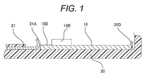
- Fig. 1 is a partial view illustrating a mounting structure for connecting between a circuit board and a connector terminal conductor in a circuit module according to an embodiment of the present invention.
- a resin molded member 20 formed integrally with a connector 20B may be referred to as a module casing for housing the circuit board or a connector member, and, depending on the application purpose, it may be referred to as a sensor cover, gear cover or the like.
- Each of stoppers 20D which retains (restrains) an one-side edge of a circuit board 18 by a hooked portion of the stopper, is provided on a surface of the cover 20, for example, an inner surface thereof.
- Each stopper 20D is formed as an elastic projection or in the form of a wall, and molded together with the resin molded member 20 (as module casing, sensor cover, gear cover, or connector member).
- the resin molded member 20 (module casing, sensor cover, gear cover or connector member) is provided with a plurality of connector-side terminal conductors 21 on an inside of the resin molded member with insert molding such that the connector-side terminal conductors 21 are partially exposed on the resin molded member 20 at an one end side respectively.
- the one end side portion of each connector-side terminal conductor 21 is formed in a hooked shape (curved portion) so as to be an elastic part 21A having elasticity.
- the elastic part 21A of each terminal conductor 21 is located opposite to the elastic part 21A, across an installation space of the circuit board 18 from the elastic part 21A.
- the circuit board 18 is caught by the stoppers 20D of the resin molded member 20 (module casing, sensor cover or gear cover) and the elastic parts 21A of the connector-side terminal conductors 21.
- Fig. 2 is a plan view of a motor-driven throttle valve controller to which a signal processing circuit board of an inductance type rotation angle sensor is attached
- Fig. 3 is an exploded perspective view thereof.
- the above circuit module is applied to this motor-driven throttle valve controller.
- the circuit board In a circuit board mounting structure for connecting between the circuit board for the throttle valve controller and the connector-side terminal conductors, the circuit board is caught between the elastic projection and the connector-side terminal conductor as in Fig. 1 , though there is some modification to the structure illustrated in Fig. 1 .
- a stationary-side annular excitation conductor 18A is printed on the circuit board 18 as a sensor signal processing circuit board and this conductor is a part which senses a rotational position. Also an electronic circuit including microcomputers 18B is attached onto the circuit board 18 and this circuit controls the operation of the rotational position sensing part and processes an output signal.
- the circuit board 18 is fixed on the resin molded member 20 as a module casing (how it is fixed will be described later).
- the resin molded member 20 not only functions as a sensor cover housing components for the rotation angle sensor but also serves as a gear cover housing the gear mechanism of a throttle valve drive mechanism (not illustrated) and a connector member having a connector.
- a position of the circuit board 18 on the resin molded member 20 is determined by a through hole 18C made in the center of the circuit board 18 and a projection 20A formed on the resin molded member 20.
- the inside of the resin molded member 20 is provided with six connector-side terminal conductors 21 made of conductive material by insert-molding.
- the connector-side terminal conductors 21 comprise four terminal conductors used for the sensor and two terminal conductors 22 used for a motor.
- the respective ends of the terminal conductors are put together in a female plug-in connector 20B formed in the resin molded member 20.
- the male plug-in connector (not illustrated), which is provided at one end of an electric wire (not illustrated) extending from an engine control unit (not illustrated), is inserted into the female plug-in connector 20B, so that the six connector-side terminal conductors (21 and 22) are electrically connected with the engine control unit to send and receive electric signals.
- the motor terminal conductor insertion area 23 is molded integrally with the resin molded member 20 so as to protrude from the inside of the resin molded member 20. So the other ends of the terminal conductors 22 are electrically connected with relay couplings 23A provided inside the motor terminal conductor insertion area 23.
- An electric connection between the terminal conductors 22 and the motor 2 is made by inserting motor-side terminal conductors '2B extending from the motor 2 into the relay couplings 23A.
- Elastic parts 21A of the connector-side terminal conductors 21, which are opposite to the female plug-in connector 20B, are exposed on the inner surface of the resin molded member 20 near the circuit board 18.
- lead terminal conductors 24 (which corresponds to the conductor parts 18D in Fig. 1 ), each which is welded to a welding-use projection 18E of conductive material provided on the circuit board 18, extend up to an edge at one end of the circuit board 18 as illustrated in the view taken from the direction of arrow P in Fig. 2 .
- the elastic parts 21A at the respective one ends of the connector-side terminal conductors 21 extend over the corresponding lead terminal conductors 24 so as to be pressed against the lead terminal conductors 24, so that the connecter-side terminal conductors and the lead terminal conductors are electrically connected to each other respectively.
- the circuit board 18 itself is pressed against the resin molded member 20 by the elastic parts 21A so as to be fixed.
- the welding-use projections 18E made of conductive material are electrically connected with corresponding circuit elements respectively.
- the microcomputer 18B and the welding-use projections 18E are electrically connected through lead terminals 18J of the microcomputer 18B, via holes 18H made in the circuit board 18 and conductors 18K printed on the front and back surfaces of the board 18.
- the welding-use projections 18E are connected to the conductors 18K by an appropriate means such as soldering or brazing.
- each welding projection 18E made of conductive material and each lead terminal conductor 24 with one end welded to the projection may be constituted by a single conductor like the conductor part 18D illustrated in Fig. 1 .
- the projection 18E made of conductive material itself is formed so as to extend to the edge of the circuit board 20 as illustrated in Fig. 1 so that the elastic part 21A at the one end of the connector-side terminal conductor 21 is pressed against the edge resulting in free of welding.
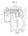
- Fig. 4 is a sectional view of the whole motor-driven throttle valve controller in which the circuit module illustrated in Figs. 2 and 3 is mounted.
- an intake air passage 1 (hereinafter referred to as a bore) and a motor housing 2A for housing the motor 2 are formed integrally with each other.
- a metal rotating shaft (hereinafter referred to as a throttle shaft) 4 is provided along a diameter of the bore 1. Both ends of the throttle shaft 4 are rotatably supported by needle bearings 5 and 6. The needle bearings 5 and 6 are press-fitted into the throttle body 3. Also, the amount of movement of the throttle shaft 4 in the axial direction is limited by inserting a C-shaped washer (hereinafter referred to as a thrust retainer) 7 in a slit on the throttle shaft 4 and then pressing the needle bearing 5 inwards.
- a C-shaped washer hereinafter referred to as a thrust retainer
- a metal circular disc-valve (hereinafter referred to as a throttle valve) 8 is inserted in the slit of the throttle shaft 4 and fixed in the throttle shaft 4 with screws 9.
- the throttle valve 8 rotates and as a consequence the opening area of the intake air passage changes, making it possible to control an intake air rate of the internal combustion engine.
- a throttle gear 10 is fixed at one end of the throttle shaft 4 with a nut 11.
- the throttle gear 10 is comprised of a metal plate 10A and a gear part 10B resin-molded on the metal plate 10A.
- the motor housing 2A is formed in parallel with the throttle shaft 4 and a brush DC motor 2 is placed into the motor housing 2A and fixed with screws 12.
- Ametal gear hereinafter referred to as a motor pinion 13 which has the smallest number of teeth among gears, is fixed on an end of the rotating shaft of the motor 2.
- the intermediate gear 15 is comprised of a large-diameter gear 15A to be engaged with the motor gear 13 and a small-diameter gear 15B to be engaged with the throttle gear 10. Both the gears are integrally formed with each other by resin molding.
- gears 13, 15A, 15B and 10 constitute a double reduction gear mechanism so that rotation of the motor 2 is transmitted through the reduction mechanism to the throttle shaft 4.
- a return spring 16 formed as a coiled spring is interposed between a back side of the throttle gear 10 and a lateral side of the throttle body 3. One end of the return spring 16 is hooked to a notch made in the throttle body 3 and the other end thereof is hooked to a notch made in the throttle gear 10.
- the return spring 16 is given a preload in the direction of rotation so as to keep the throttle valve 8 fully open while the motor 2 is not turned on.
- the abovementioned circuit module in Figs. 2 and 3 namely the resin molded member 20 including the connector 20B and the circuit board 18 and having the structure for connecting between the circuit board and connector terminal conductors which characterizes this embodiment, is attached so as to cover the reduction gear mechanism which is located on the throttle body 3 and a lateral side of the motor housing.
- a rotatable excitation conductor inductance type rotation angle sensor
- inductance type rotation angle sensor in the form of a rotating plate located at one end of the throttle shaft 4 faces the stationary-side excitation conductor 18 of the abovementioned circuit module (resin molded member 20).
- the inductance type rotation angle sensor can sense a rotational angle as a rotational position of the rotatable excitation conductor, by taking advantage of the fact that the inductance between the rotatable excitation conductor attached to the rotating shaft and the stationary-side excitation conductor varies depending on a positional relation between both excitation conductors. Since such an inductance type rotation angle sensor is an already known technique (for example, JP-A-2008-96231 ), detailed description thereof is omitted here.
- the invention may be widely used as a mounting structure having such a circuit board fixed on a member with a connector formed thereon, terminal conductors used for the circuit board, and terminal conductors used for the connector electrically being connected to each other.
Landscapes
- Engineering & Computer Science (AREA)
- Chemical & Material Sciences (AREA)
- Combustion & Propulsion (AREA)
- Mechanical Engineering (AREA)
- General Engineering & Computer Science (AREA)
- Microelectronics & Electronic Packaging (AREA)
- Control Of Throttle Valves Provided In The Intake System Or In The Exhaust System (AREA)
- Mounting Of Printed Circuit Boards And The Like (AREA)
- Motor Or Generator Frames (AREA)
Applications Claiming Priority (2)
| Application Number | Priority Date | Filing Date | Title |
|---|---|---|---|
| JP2009232090A JP5235833B2 (ja) | 2009-10-06 | 2009-10-06 | 回路基板とコネクタターミナル導体との接続実装構造 |
| PCT/JP2010/005994 WO2011043070A1 (ja) | 2009-10-06 | 2010-10-06 | コネクタを有する回路モジュール |
Publications (3)
| Publication Number | Publication Date |
|---|---|
| EP2487351A1 true EP2487351A1 (de) | 2012-08-15 |
| EP2487351A4 EP2487351A4 (de) | 2014-07-23 |
| EP2487351B1 EP2487351B1 (de) | 2015-09-09 |
Family
ID=43856552
Family Applications (1)
| Application Number | Title | Priority Date | Filing Date |
|---|---|---|---|
| EP10821745.6A Not-in-force EP2487351B1 (de) | 2009-10-06 | 2010-10-06 | Schaltkreismodul mit stecker(n) |
Country Status (4)
| Country | Link |
|---|---|
| EP (1) | EP2487351B1 (de) |
| JP (1) | JP5235833B2 (de) |
| CN (1) | CN102667108B (de) |
| WO (1) | WO2011043070A1 (de) |
Cited By (3)
| Publication number | Priority date | Publication date | Assignee | Title |
|---|---|---|---|---|
| FR3016229A1 (fr) * | 2014-01-07 | 2015-07-10 | Systemes Et Technologies Identification Stid | Lecteur de controle d’acces et module complementaire de controle |
| US10091895B2 (en) | 2014-01-07 | 2018-10-02 | Systemes Et Technologies Identification (Stid) | Access control reader with an opening detection device |
| US11892324B2 (en) | 2018-09-21 | 2024-02-06 | Denso Corporation | Rotation angle sensor and method for manufacturing rotation angle sensor |
Families Citing this family (4)
| Publication number | Priority date | Publication date | Assignee | Title |
|---|---|---|---|---|
| JP5987877B2 (ja) * | 2013-10-04 | 2016-09-07 | 株式会社デンソー | 電子スロットル |
| JP6684957B2 (ja) * | 2017-03-14 | 2020-04-22 | アルプスアルパイン株式会社 | 固定導電板と弾性導電板を有する電子装置 |
| EP3842734B1 (de) * | 2018-08-23 | 2024-05-08 | Mikuni Corporation | Elektronisch gesteuerte drosselvorrichtung für einen motor |
| WO2025220229A1 (ja) * | 2024-04-19 | 2025-10-23 | ファナック株式会社 | ハウジングおよび電子機器 |
Family Cites Families (10)
| Publication number | Priority date | Publication date | Assignee | Title |
|---|---|---|---|---|
| JPS5892784U (ja) * | 1981-12-15 | 1983-06-23 | 松下電工株式会社 | プリント基板保持構造 |
| JPH0526961Y2 (de) * | 1985-12-09 | 1993-07-08 | ||
| JP3394407B2 (ja) * | 1996-12-25 | 2003-04-07 | 株式会社三協精機製作所 | モータ駆動装置 |
| EP1167724B1 (de) * | 1999-03-29 | 2004-05-26 | Hitachi, Ltd. | Elektronisch geregelte drosselklappe |
| JP2001124509A (ja) * | 1999-10-22 | 2001-05-11 | Aisan Ind Co Ltd | ロータリポジションセンサ |
| JP2002368450A (ja) * | 2001-06-05 | 2002-12-20 | Toyota Industries Corp | 半導体装置の端子構造 |
| JP3787518B2 (ja) * | 2001-11-27 | 2006-06-21 | ポリマテック株式会社 | シーリングコネクタ及び小型情報通信機器の内部音響構造 |
| JP2003254782A (ja) * | 2002-03-05 | 2003-09-10 | Yoshikazu Ichiyama | 角度位置検出器 |
| JP5147213B2 (ja) * | 2006-10-11 | 2013-02-20 | 日立オートモティブシステムズ株式会社 | インダクタンス式回転角度検出装置及びそれを備えたモータ駆動式の絞り弁制御装置 |
| WO2009010705A1 (en) * | 2007-07-18 | 2009-01-22 | Autoliv Development Ab | An electrical unit |
-
2009
- 2009-10-06 JP JP2009232090A patent/JP5235833B2/ja not_active Expired - Fee Related
-
2010
- 2010-10-06 CN CN201080043824.7A patent/CN102667108B/zh not_active Expired - Fee Related
- 2010-10-06 WO PCT/JP2010/005994 patent/WO2011043070A1/ja not_active Ceased
- 2010-10-06 EP EP10821745.6A patent/EP2487351B1/de not_active Not-in-force
Cited By (5)
| Publication number | Priority date | Publication date | Assignee | Title |
|---|---|---|---|---|
| FR3016229A1 (fr) * | 2014-01-07 | 2015-07-10 | Systemes Et Technologies Identification Stid | Lecteur de controle d’acces et module complementaire de controle |
| WO2015104486A1 (fr) * | 2014-01-07 | 2015-07-16 | Systemes Et Technologies Identification (Stid) | Lecteur de controle d'acces et module complementaire de controle |
| US10008059B2 (en) | 2014-01-07 | 2018-06-26 | Systemes Et Technologies Identification (Stid) | Access control reader and complementary control module |
| US10091895B2 (en) | 2014-01-07 | 2018-10-02 | Systemes Et Technologies Identification (Stid) | Access control reader with an opening detection device |
| US11892324B2 (en) | 2018-09-21 | 2024-02-06 | Denso Corporation | Rotation angle sensor and method for manufacturing rotation angle sensor |
Also Published As
| Publication number | Publication date |
|---|---|
| JP5235833B2 (ja) | 2013-07-10 |
| WO2011043070A1 (ja) | 2011-04-14 |
| CN102667108A (zh) | 2012-09-12 |
| JP2011080390A (ja) | 2011-04-21 |
| CN102667108B (zh) | 2015-05-20 |
| EP2487351B1 (de) | 2015-09-09 |
| EP2487351A4 (de) | 2014-07-23 |
Similar Documents
| Publication | Publication Date | Title |
|---|---|---|
| EP2487351B1 (de) | Schaltkreismodul mit stecker(n) | |
| JP5066142B2 (ja) | インダクティブ型スロットルセンサ付きモータ駆動型スロットルバルブ装置、およびモータ駆動型スロットルバルブ装置のスロットルシャフトの回転角度を検出するためのインダクティブ型スロットルセンサ | |
| US8853902B2 (en) | Displacement drive, in particular window lifter drive | |
| US9976333B2 (en) | Adjusting drive, in particular window lifter drive | |
| EP2023467A1 (de) | Motor mit reduktionsgetriebe und herstellungsverfahren dafür | |
| US5963124A (en) | Cover mounted position sensor | |
| JP6234713B2 (ja) | ギヤボックスおよびギヤボックスの製造方法 | |
| KR20050051712A (ko) | 모터 | |
| JP4394530B2 (ja) | 電動駆動装置 | |
| CN103812279B (zh) | 电动机 | |
| WO2004009424A1 (ja) | 電動パワーステアリング装置 | |
| CN106411041A (zh) | 驱动单元 | |
| CN112424460A (zh) | 电控节气门装置 | |
| JP2004147490A (ja) | モータ | |
| CN114865825A (zh) | 自动开闭装置和马桶 | |
| CN1383601A (zh) | 带可调电位器的变速驱动装置 | |
| JP4255792B2 (ja) | モータ | |
| US8671910B2 (en) | Intake air quantity control device for internal combustion engine | |
| JP4549582B2 (ja) | モータ及びモータの中間コネクタ製造方法 | |
| CN216625412U (zh) | 马达和泵装置 | |
| EP1659375A1 (de) | Modularen Encoder, Fertigungsverfahren für einen modularen Encoder, und Messsystem für Drehbewegungen | |
| JPH0237256Y2 (de) | ||
| CN223001495U (zh) | 线束支撑装置以及车辆转向柱连接结构 | |
| EP3822589A1 (de) | Detektionsvorrichtung | |
| JP4456433B2 (ja) | ブラシホルダの製造方法 |
Legal Events
| Date | Code | Title | Description |
|---|---|---|---|
| PUAI | Public reference made under article 153(3) epc to a published international application that has entered the european phase |
Free format text: ORIGINAL CODE: 0009012 |
|
| 17P | Request for examination filed |
Effective date: 20120507 |
|
| AK | Designated contracting states |
Kind code of ref document: A1 Designated state(s): AL AT BE BG CH CY CZ DE DK EE ES FI FR GB GR HR HU IE IS IT LI LT LU LV MC MK MT NL NO PL PT RO RS SE SI SK SM TR |
|
| DAX | Request for extension of the european patent (deleted) | ||
| A4 | Supplementary search report drawn up and despatched |
Effective date: 20140623 |
|
| RIC1 | Information provided on ipc code assigned before grant |
Ipc: F02D 9/10 20060101AFI20140616BHEP Ipc: H01R 12/72 20110101ALI20140616BHEP Ipc: F02D 11/10 20060101ALI20140616BHEP Ipc: H05K 5/00 20060101ALI20140616BHEP |
|
| REG | Reference to a national code |
Ref country code: DE Ref legal event code: R079 Ref document number: 602010027466 Country of ref document: DE Free format text: PREVIOUS MAIN CLASS: F02D0009000000 Ipc: F02D0009100000 |
|
| RIC1 | Information provided on ipc code assigned before grant |
Ipc: H05K 5/00 20060101ALI20150113BHEP Ipc: H01R 12/72 20110101ALI20150113BHEP Ipc: F02D 9/10 20060101AFI20150113BHEP Ipc: F02D 11/10 20060101ALI20150113BHEP |
|
| GRAP | Despatch of communication of intention to grant a patent |
Free format text: ORIGINAL CODE: EPIDOSNIGR1 |
|
| INTG | Intention to grant announced |
Effective date: 20150324 |
|
| GRAS | Grant fee paid |
Free format text: ORIGINAL CODE: EPIDOSNIGR3 |
|
| GRAA | (expected) grant |
Free format text: ORIGINAL CODE: 0009210 |
|
| AK | Designated contracting states |
Kind code of ref document: B1 Designated state(s): AL AT BE BG CH CY CZ DE DK EE ES FI FR GB GR HR HU IE IS IT LI LT LU LV MC MK MT NL NO PL PT RO RS SE SI SK SM TR |
|
| REG | Reference to a national code |
Ref country code: GB Ref legal event code: FG4D |
|
| REG | Reference to a national code |
Ref country code: AT Ref legal event code: REF Ref document number: 748330 Country of ref document: AT Kind code of ref document: T Effective date: 20150915 Ref country code: CH Ref legal event code: EP |
|
| REG | Reference to a national code |
Ref country code: IE Ref legal event code: FG4D |
|
| REG | Reference to a national code |
Ref country code: DE Ref legal event code: R096 Ref document number: 602010027466 Country of ref document: DE |
|
| REG | Reference to a national code |
Ref country code: NL Ref legal event code: MP Effective date: 20150909 |
|
| PG25 | Lapsed in a contracting state [announced via postgrant information from national office to epo] |
Ref country code: NO Free format text: LAPSE BECAUSE OF FAILURE TO SUBMIT A TRANSLATION OF THE DESCRIPTION OR TO PAY THE FEE WITHIN THE PRESCRIBED TIME-LIMIT Effective date: 20151209 Ref country code: LT Free format text: LAPSE BECAUSE OF FAILURE TO SUBMIT A TRANSLATION OF THE DESCRIPTION OR TO PAY THE FEE WITHIN THE PRESCRIBED TIME-LIMIT Effective date: 20150909 Ref country code: LV Free format text: LAPSE BECAUSE OF FAILURE TO SUBMIT A TRANSLATION OF THE DESCRIPTION OR TO PAY THE FEE WITHIN THE PRESCRIBED TIME-LIMIT Effective date: 20150909 Ref country code: GR Free format text: LAPSE BECAUSE OF FAILURE TO SUBMIT A TRANSLATION OF THE DESCRIPTION OR TO PAY THE FEE WITHIN THE PRESCRIBED TIME-LIMIT Effective date: 20151210 Ref country code: FI Free format text: LAPSE BECAUSE OF FAILURE TO SUBMIT A TRANSLATION OF THE DESCRIPTION OR TO PAY THE FEE WITHIN THE PRESCRIBED TIME-LIMIT Effective date: 20150909 |
|
| REG | Reference to a national code |
Ref country code: LT Ref legal event code: MG4D |
|
| REG | Reference to a national code |
Ref country code: AT Ref legal event code: MK05 Ref document number: 748330 Country of ref document: AT Kind code of ref document: T Effective date: 20150909 |
|
| PG25 | Lapsed in a contracting state [announced via postgrant information from national office to epo] |
Ref country code: RS Free format text: LAPSE BECAUSE OF FAILURE TO SUBMIT A TRANSLATION OF THE DESCRIPTION OR TO PAY THE FEE WITHIN THE PRESCRIBED TIME-LIMIT Effective date: 20150909 Ref country code: ES Free format text: LAPSE BECAUSE OF FAILURE TO SUBMIT A TRANSLATION OF THE DESCRIPTION OR TO PAY THE FEE WITHIN THE PRESCRIBED TIME-LIMIT Effective date: 20150909 Ref country code: HR Free format text: LAPSE BECAUSE OF FAILURE TO SUBMIT A TRANSLATION OF THE DESCRIPTION OR TO PAY THE FEE WITHIN THE PRESCRIBED TIME-LIMIT Effective date: 20150909 Ref country code: SE Free format text: LAPSE BECAUSE OF FAILURE TO SUBMIT A TRANSLATION OF THE DESCRIPTION OR TO PAY THE FEE WITHIN THE PRESCRIBED TIME-LIMIT Effective date: 20150909 |
|
| PG25 | Lapsed in a contracting state [announced via postgrant information from national office to epo] |
Ref country code: NL Free format text: LAPSE BECAUSE OF FAILURE TO SUBMIT A TRANSLATION OF THE DESCRIPTION OR TO PAY THE FEE WITHIN THE PRESCRIBED TIME-LIMIT Effective date: 20150909 |
|
| PG25 | Lapsed in a contracting state [announced via postgrant information from national office to epo] |
Ref country code: EE Free format text: LAPSE BECAUSE OF FAILURE TO SUBMIT A TRANSLATION OF THE DESCRIPTION OR TO PAY THE FEE WITHIN THE PRESCRIBED TIME-LIMIT Effective date: 20150909 Ref country code: IT Free format text: LAPSE BECAUSE OF FAILURE TO SUBMIT A TRANSLATION OF THE DESCRIPTION OR TO PAY THE FEE WITHIN THE PRESCRIBED TIME-LIMIT Effective date: 20150909 Ref country code: IS Free format text: LAPSE BECAUSE OF FAILURE TO SUBMIT A TRANSLATION OF THE DESCRIPTION OR TO PAY THE FEE WITHIN THE PRESCRIBED TIME-LIMIT Effective date: 20160109 Ref country code: SK Free format text: LAPSE BECAUSE OF FAILURE TO SUBMIT A TRANSLATION OF THE DESCRIPTION OR TO PAY THE FEE WITHIN THE PRESCRIBED TIME-LIMIT Effective date: 20150909 Ref country code: CZ Free format text: LAPSE BECAUSE OF FAILURE TO SUBMIT A TRANSLATION OF THE DESCRIPTION OR TO PAY THE FEE WITHIN THE PRESCRIBED TIME-LIMIT Effective date: 20150909 |
|
| PG25 | Lapsed in a contracting state [announced via postgrant information from national office to epo] |
Ref country code: PT Free format text: LAPSE BECAUSE OF FAILURE TO SUBMIT A TRANSLATION OF THE DESCRIPTION OR TO PAY THE FEE WITHIN THE PRESCRIBED TIME-LIMIT Effective date: 20160111 Ref country code: AT Free format text: LAPSE BECAUSE OF FAILURE TO SUBMIT A TRANSLATION OF THE DESCRIPTION OR TO PAY THE FEE WITHIN THE PRESCRIBED TIME-LIMIT Effective date: 20150909 Ref country code: PL Free format text: LAPSE BECAUSE OF FAILURE TO SUBMIT A TRANSLATION OF THE DESCRIPTION OR TO PAY THE FEE WITHIN THE PRESCRIBED TIME-LIMIT Effective date: 20150909 Ref country code: RO Free format text: LAPSE BECAUSE OF FAILURE TO SUBMIT A TRANSLATION OF THE DESCRIPTION OR TO PAY THE FEE WITHIN THE PRESCRIBED TIME-LIMIT Effective date: 20150909 |
|
| REG | Reference to a national code |
Ref country code: CH Ref legal event code: PL |
|
| REG | Reference to a national code |
Ref country code: DE Ref legal event code: R097 Ref document number: 602010027466 Country of ref document: DE |
|
| PG25 | Lapsed in a contracting state [announced via postgrant information from national office to epo] |
Ref country code: MC Free format text: LAPSE BECAUSE OF FAILURE TO SUBMIT A TRANSLATION OF THE DESCRIPTION OR TO PAY THE FEE WITHIN THE PRESCRIBED TIME-LIMIT Effective date: 20150909 |
|
| PLBE | No opposition filed within time limit |
Free format text: ORIGINAL CODE: 0009261 |
|
| STAA | Information on the status of an ep patent application or granted ep patent |
Free format text: STATUS: NO OPPOSITION FILED WITHIN TIME LIMIT |
|
| REG | Reference to a national code |
Ref country code: IE Ref legal event code: MM4A |
|
| PG25 | Lapsed in a contracting state [announced via postgrant information from national office to epo] |
Ref country code: CH Free format text: LAPSE BECAUSE OF NON-PAYMENT OF DUE FEES Effective date: 20151031 Ref country code: LI Free format text: LAPSE BECAUSE OF NON-PAYMENT OF DUE FEES Effective date: 20151031 |
|
| REG | Reference to a national code |
Ref country code: FR Ref legal event code: ST Effective date: 20160630 |
|
| 26N | No opposition filed |
Effective date: 20160610 |
|
| GBPC | Gb: european patent ceased through non-payment of renewal fee |
Effective date: 20151209 |
|
| PG25 | Lapsed in a contracting state [announced via postgrant information from national office to epo] |
Ref country code: FR Free format text: LAPSE BECAUSE OF NON-PAYMENT OF DUE FEES Effective date: 20151109 Ref country code: DK Free format text: LAPSE BECAUSE OF FAILURE TO SUBMIT A TRANSLATION OF THE DESCRIPTION OR TO PAY THE FEE WITHIN THE PRESCRIBED TIME-LIMIT Effective date: 20150909 Ref country code: SI Free format text: LAPSE BECAUSE OF FAILURE TO SUBMIT A TRANSLATION OF THE DESCRIPTION OR TO PAY THE FEE WITHIN THE PRESCRIBED TIME-LIMIT Effective date: 20150909 |
|
| PG25 | Lapsed in a contracting state [announced via postgrant information from national office to epo] |
Ref country code: GB Free format text: LAPSE BECAUSE OF NON-PAYMENT OF DUE FEES Effective date: 20151209 Ref country code: IE Free format text: LAPSE BECAUSE OF NON-PAYMENT OF DUE FEES Effective date: 20151006 |
|
| PG25 | Lapsed in a contracting state [announced via postgrant information from national office to epo] |
Ref country code: BE Free format text: LAPSE BECAUSE OF FAILURE TO SUBMIT A TRANSLATION OF THE DESCRIPTION OR TO PAY THE FEE WITHIN THE PRESCRIBED TIME-LIMIT Effective date: 20150909 |
|
| PG25 | Lapsed in a contracting state [announced via postgrant information from national office to epo] |
Ref country code: SM Free format text: LAPSE BECAUSE OF FAILURE TO SUBMIT A TRANSLATION OF THE DESCRIPTION OR TO PAY THE FEE WITHIN THE PRESCRIBED TIME-LIMIT Effective date: 20150909 Ref country code: BG Free format text: LAPSE BECAUSE OF FAILURE TO SUBMIT A TRANSLATION OF THE DESCRIPTION OR TO PAY THE FEE WITHIN THE PRESCRIBED TIME-LIMIT Effective date: 20150909 Ref country code: HU Free format text: LAPSE BECAUSE OF FAILURE TO SUBMIT A TRANSLATION OF THE DESCRIPTION OR TO PAY THE FEE WITHIN THE PRESCRIBED TIME-LIMIT; INVALID AB INITIO Effective date: 20101006 |
|
| PG25 | Lapsed in a contracting state [announced via postgrant information from national office to epo] |
Ref country code: CY Free format text: LAPSE BECAUSE OF FAILURE TO SUBMIT A TRANSLATION OF THE DESCRIPTION OR TO PAY THE FEE WITHIN THE PRESCRIBED TIME-LIMIT Effective date: 20150909 |
|
| PG25 | Lapsed in a contracting state [announced via postgrant information from national office to epo] |
Ref country code: TR Free format text: LAPSE BECAUSE OF FAILURE TO SUBMIT A TRANSLATION OF THE DESCRIPTION OR TO PAY THE FEE WITHIN THE PRESCRIBED TIME-LIMIT Effective date: 20150909 Ref country code: MT Free format text: LAPSE BECAUSE OF FAILURE TO SUBMIT A TRANSLATION OF THE DESCRIPTION OR TO PAY THE FEE WITHIN THE PRESCRIBED TIME-LIMIT Effective date: 20150909 |
|
| PG25 | Lapsed in a contracting state [announced via postgrant information from national office to epo] |
Ref country code: LU Free format text: LAPSE BECAUSE OF NON-PAYMENT OF DUE FEES Effective date: 20151006 |
|
| PG25 | Lapsed in a contracting state [announced via postgrant information from national office to epo] |
Ref country code: MK Free format text: LAPSE BECAUSE OF FAILURE TO SUBMIT A TRANSLATION OF THE DESCRIPTION OR TO PAY THE FEE WITHIN THE PRESCRIBED TIME-LIMIT Effective date: 20150909 |
|
| PG25 | Lapsed in a contracting state [announced via postgrant information from national office to epo] |
Ref country code: AL Free format text: LAPSE BECAUSE OF FAILURE TO SUBMIT A TRANSLATION OF THE DESCRIPTION OR TO PAY THE FEE WITHIN THE PRESCRIBED TIME-LIMIT Effective date: 20150909 |
|
| REG | Reference to a national code |
Ref country code: DE Ref legal event code: R082 Ref document number: 602010027466 Country of ref document: DE Representative=s name: MERH-IP MATIAS ERNY REICHL HOFFMANN PATENTANWA, DE Ref country code: DE Ref legal event code: R081 Ref document number: 602010027466 Country of ref document: DE Owner name: HITACHI ASTEMO, LTD., HITACHINAKA-SHI, JP Free format text: FORMER OWNER: HITACHI AUTOMOTIVE SYSTEMS, LTD., HITACHINAKA-SHI, IBARAKI, JP |
|
| PGFP | Annual fee paid to national office [announced via postgrant information from national office to epo] |
Ref country code: DE Payment date: 20210831 Year of fee payment: 12 |
|
| REG | Reference to a national code |
Ref country code: DE Ref legal event code: R119 Ref document number: 602010027466 Country of ref document: DE |
|
| PG25 | Lapsed in a contracting state [announced via postgrant information from national office to epo] |
Ref country code: DE Free format text: LAPSE BECAUSE OF NON-PAYMENT OF DUE FEES Effective date: 20230503 |