EP2487449A2 - Lunette de visée dotée d'une lentille de correction de champ - Google Patents
Lunette de visée dotée d'une lentille de correction de champ Download PDFInfo
- Publication number
- EP2487449A2 EP2487449A2 EP20120154951 EP12154951A EP2487449A2 EP 2487449 A2 EP2487449 A2 EP 2487449A2 EP 20120154951 EP20120154951 EP 20120154951 EP 12154951 A EP12154951 A EP 12154951A EP 2487449 A2 EP2487449 A2 EP 2487449A2
- Authority
- EP
- European Patent Office
- Prior art keywords
- lens
- eyepiece
- image plane
- field lens
- side image
- Prior art date
- Legal status (The legal status is an assumption and is not a legal conclusion. Google has not performed a legal analysis and makes no representation as to the accuracy of the status listed.)
- Granted
Links
Images






Classifications
-
- F—MECHANICAL ENGINEERING; LIGHTING; HEATING; WEAPONS; BLASTING
- F41—WEAPONS
- F41G—WEAPON SIGHTS; AIMING
- F41G1/00—Sighting devices
- F41G1/38—Telescopic sights specially adapted for smallarms or ordnance; Supports or mountings therefor
Definitions
- the invention relates to a telescopic sight according to the preamble of claim 1.
- Rifle scopes are used in hunting and in the military for targeting targets at great distances by means of weapons.
- the lens arrangement has at least one objective and one eyepiece.
- the objective is a collecting optical system for real optical imaging of the target object and the eyepiece is a lens system through which one eye looks into the lens arrangement.
- An intermediate image designed by the objective in an objective-side image plane is magnified in an eyepiece-side image plane.
- the magnification however, the viewing angle is very limited and objects at a shorter distance can be poorly sighted or viewed.
- the prior art provides a variable magnification, the so-called zoom.
- the targeted object in the lens-side image plane is reversed and upside down and must therefore be corrected.
- a reversal system is used within the riflescope.
- This allows an axial independent or defined displacement of two optical elements.
- the optical elements include lenses, Kittlinsen and Reticle.
- an intermediate image generated in the lens-side image plane is erected and enlarged in the eyepiece-side image plane where it is viewed.
- each individual lens produces different aberrations in the optical imaging of the object into a virtual or real intermediate image, including spherical aberration, defocus, coma, field curvature, distortion, longitudinal and transverse color aberrations in various orders.
- the lenses are combined and arranged in the objective of a riflescope in such a way that the errors over the beam path from the object to the image compensate each other as well as possible.
- flint and crown glass lattices are used to correct the chromatic aberrations.
- optical means Despite the use of optical means remains in the first image plane always a certain amount of aberrations, especially in combinatorial binoculars or riflescopes, especially at a more than fourfold magnification, in the eyepiece image plane at a high magnification are increasingly visible. Transverse aberrations are magnified linearly and longitudinal errors are magnified quadratically.
- the prior art provides to reduce the image errors by clever design of the lens system so that a consistently good image quality over the entire magnification range is guaranteed.
- a combatzoomiges rifle scope is for example in EP 1 746 451 B1 described.
- This describes a telescopic sight, with a central tube, which is arranged between a lens and an eyepiece.
- the center tube contains a reversing system, in which an adjustable magnification optics is integrated.
- This consists of two relatively movable optical elements.
- the reversing system is arranged between an objective-side image plane and an eyepiece-side image plane. By moving the optical elements, an intermediate image designed by the objective in the lens-side image plane is enlarged and erected with a variable magnification in the eyepiece-side image plane.
- the maximum magnification is at least fourfold.
- an optical beam deflection device is integrated into the reversing system.
- This consists of an additional lens arrangement which is arranged on the eyepiece facing side of the reversing system and has a negative refractive power between -20 dpt (diopters) and - 40 dpt. This expands the magnification range. This ensures a subjective field of view of the telescopic sight of at least 22 °, at least for light with a wavelength of about 550 nm at all magnifications.
- the reversing system on the object side spaced from the lens-side image plane has a field lens, by means of which a beam coming from the lens of an object point lying on the field of view can be guided through the narrow channel of the reversing system.
- This field lens also has the task of moving the magnification range of the riflescope and is not used primarily for image aberration correction.
- the object of the invention is therefore to reduce the aberrations over the entire magnification range, especially in the edge region and even at low magnifications, the solution should cause a low mechanical complexity and low cost.
- the riflescope should remain easy and comfortable to handle and have a long service life.
- a telescopic sight with a arranged between a lens and an eyepiece reversing system having an objective-side field lens and eyepiece at least two relatively displaceable optical elements, with a lying between the lens and the field lens and the field lens spaced lens side image plane and between the eyepiece and the eyepiece-side image plane underlying the inversion system, wherein an intermediate image designed by the lens in the lens-side image plane is displayed in the eyepiece image plane by the displacement of the optical elements and with at least four times the maximum magnification
- the invention provides that between the lens side image plane and the field lens a correction field lens is arranged.
- Such a correction field lens is not movable, which increases the complexity of the scope only slightly.
- image errors are less pronounced in the inverse system. This considerably increases the image quality.
- the correction field lens is insensitive to vibrations as well as thermal changes that result from the use under different operating conditions. This results in a long life of the riflescope.
- the actuating forces for the movable optical elements are not increased, which would require a more stable and thus heavier design.
- the few additional components required increase the weight of the riflescope only insignificantly.
- the scope remains light, comfortable and easy to handle.
- the particular advantages of the correction lens at the position according to the invention result from the correction of various aberrations that are less pronounced on the eyepiece-side image plane occur. Particularly advantageous is the position between the lens-side image plane and the field lens. Through this, the image aberration changes depending on the position of the movable optical elements and thus the magnification. It is now possible to design the image aberration correction over the entire zoom range in such a way that a brilliant, sharp and well-illuminated image is displayed on the eyepiece-side image plane. A third movable optical element in the inverse system is not required.
- a beam path is influenced in such a way that inter alia the spherical aberration and the coma are reduced at all magnifications, but in particular at the small magnification, in the eyepiece-side image plane, but also astigmatism and field curvature are reduced.
- the correction field lens serves to correct the aberrations already coming out of the objective, but also to compensate for the aberrations arising in the reversal system, so that the best possible image is produced in the eyepiece-side image plane.
- the correction field lens is arranged between the lens-side image plane and the field lens, since this allows the errors from the lens to be corrected.
- the following table shows the influence of the inventive correction field lens on 3rd order aberrations, according to an optical design program according to MIL-HDBK-141 (Military Standardization Handbook: Optical Design): Image defect intensity from optical design program according to MIL-HDBK-141 WITHOUT CORRECTION FIELD LENS WITH CORRECTION FIELD LENS Picture Error Type Small magnification Medium magnification Big magnification Small magnification Medium magnification Big magnification Spherical aberration 0.821086 0.150681 0.235905 0.448830 0.106225 0.187797 coma -0.199421 -0.100022 0.100028 -0.051632 -0.100011 0.100030 Tangential astigmatism 0.307891 -0.011196 0.067351 0.066316 -0.051988 0.033315 Sagittal astaxism 0.239279 0.023984 0.037844 0.136409 0.004444 0.023182 Curvature of field 0.204973 0.0415
- the correction field lens is arranged on the side of the lens-side image plane facing away from the objective.
- the lens can be designed with a plan side facing the lens and can be arranged directly at the lens-side image plane. This allows cementing with a reticle or reticle. As a result, the transmission is not significantly reduced, and the otherwise high sensitivity of the two mutually facing glass surfaces of reticle and correction field lens against the visibility of scratches is significantly reduced in the cemented surface.
- the correction field lens is collecting or scattering. This may be convex, concave or flat. Particularly advantageous is a spherical and / or planar surface, since such a correction field lens costs significantly less than aspherical lenses.
- a development provides that a reticle is arranged on the correction field lens, preferably in the lens-side image plane.
- the correction field lens is cemented to the reticle. This reduces the complexity of the optical arrangement and the necessary fastening means. Thermal influences and vibrations have no increased effect on the optical arrangement. Thus, the weight of the riflescope remains low and it results in a good comfortable handling. In principle, however, it would also be possible to arrange the reticle in the eyepiece image plane, as it is found especially in the American market.
- a beam splitter is arranged between the eyepiece-side image plane and the eyepiece. This can be used to reflect another target in the riflescope.
- a variant of the invention provides that the objective consists of an objective lens and an objective achromat arranged between the objective lens and the objective-side image plane.
- a further lens achromat can be provided, which is arranged on the same side of the objective lens or the opposite side of this.
- the eyepiece consists of an eyepiece lens and an eyepiece achromat arranged between the eyepiece lens and the eyepiece-side image plane.
- the second optical element is arranged closer to the eyepiece than the first optical element, and that in the inversion system a beam deflecting device with negative refractive power is arranged between the second optical element and the eyepiece-side image plane.
- the magnification range is widened. This is particularly advantageous in combinatorial processes.
- the correction field lens is particularly advantageous for improving the image quality if the maximum magnification of the intermediate image on the eyepiece-side image plane is at least fivefold, but preferably at least sixfold and particularly preferably at least eightfold. Especially with large magnification ranges, a sharp and brilliant image over the entire image area, in particular up to the edge of the image, is thus achieved even at the low magnifications.
- Fig. 1 shows a cross section through an inventive optical arrangement of a riflescope with a beam path SG.
- a reversing system 30 is arranged between an objective 10 and an eyepiece 20, a reversing system 30 is arranged.
- the inverting system 30 includes an objective-side field lens 50 and eyepiece side two relatively displaceable optical elements 31, 32, wherein the second optical element 32 is disposed closer to the eyepiece 20 than the first optical element 31.
- an object lens side image plane BE1 spaced apart from the field lens 50.
- an eyepiece-side image plane BE2 lies between the eyepiece 20 and the reversing system 30.
- the objective 10 consists of a first objective achromat 12, an objective lens 11 arranged between the objective achromat 12 and the lens-side image plane BE1, and a second objective achromat 13 arranged between the objective lens 11 and the lens-side image plane BE1.
- the eyepiece 20 consists of an eyepiece lens 21 and an eyepiece achromat 22 arranged between the eyepiece lens 21 and the eyepiece-side image plane BE2.
- a beam splitter 60 and a beam deflector 70 are provided.
- the beam splitter 60 is arranged between the eyepiece-side image plane BE2 and the eyepiece 20.
- the beam deflection device 70 has a negative refractive power and is located in the inversion system 30 between the second optical element 32 and the eyepiece-side image plane BE2.
- a correction field lens 40 is furthermore arranged between the lens-side image plane BE1 and the field lens 50. This is cemented with a reticle 41, which is positioned in the lens-side image plane BE1. Due to the physical extent of the reticle 41, a part of it lies between the objective 10 and the objective-side image plane BE1 and a part between the objective-side image plane BE1 and the field lens 50.
- the actual correction lens 40 is around the part of the reticle 41 in the direction of the field lens 50 spaced from the lens-side image plane BE1, by which the reticle 41 on the side of the field lens 50 projects beyond the lens-side image plane BE1.
- an intermediate image designed by the objective 10 in the lens-side image plane BE1 is displayed with a variable magnification erected in the eyepiece-side image plane BE2.
- the field lens 50 serves to concentrate the beam path SG to a diameter of the first displaceable optical element 31.
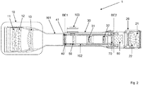
- Fig. 2 shows a cross section through a telescopic sight 1, in which the features of the optical arrangement of Fig. 1 are integrated.
- a reversing system 30 is disposed within a tube 102 between a lens 10 and an eyepiece 20.
- the tube 102 is adjustably positionable within the housing 101 by means of an adjusting wheel 103. This makes it possible to adjust the position of a reticle in order to be able to adjust the optical target acquisition and the meeting point location of a projectile. Without such an adjustment, the point of impact could deviate from the target because of the trajectory of the projectile, which is affected by, among other things, gravity and wind energy.
- the reversing system 30 has an objective-side field lens 50 and eyepiece-side two relatively movable optical elements 31, 32, wherein the second optical element 32 is disposed closer to the eyepiece 20 than the first optical element 31. Between the lens 10 and the field lens 50 is a to the field lens 50 spaced lens side image plane BE1. In addition, an eyepiece-side image plane BE2 lies between the eyepiece 20 and the reversing system 30.
- the objective 10 consists of an objective lens 11 and two objective achromats 12, 13 arranged between the objective lens 11 and the objective-side image plane BE1.
- the eyepiece 20 consists of an eyepiece lens 21 and an eyepiece arranged between the eyepiece lens 21 and the eyepiece-side image plane BE2
- the eyepiece 20 consists of an eyepiece lens 21 and an eyepiece achromat 22 arranged between the eyepiece lens 21 and the eyepiece-side image plane BE2.
- a correction field lens 40 is further arranged in the tube 102 between the lens-side image plane BE1 and the field lens 50. This is cemented with a reticle 41, which is positioned in the lens-side image plane BE1.
- the rifle scope 1 has a beam splitter 60 and a beam deflection device 70.
- the beam splitter 60 is fixed between the eyepiece-side image plane BE2 and the eyepiece 20 in the housing 101.
- the beam deflection device 70 has a negative refractive power and is located in the inversion system 30 between the second optical element 32 and the eyepiece-side image plane BE2. It is like the rest of the inversion system 30 disposed in the tube 102.
- an intermediate image designed by the objective 10 in the lens-side image plane BE1 is displayed with a variable magnification erected in the eyepiece-side image plane BE2.
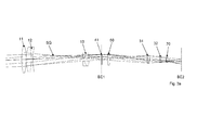
- Fig. 3a and Fig. 3b each show an optical arrangement.
- a lens consisting of an objective lens 11 and two lens achromats 12, 13 and an eyepiece-side image plane BE2
- a reversing system is arranged between a lens, consisting of an objective lens 11 and two lens achromats 12, 13 and an eyepiece-side image plane BE2
- the inversion system has an objective-side field lens 50 and eyepiece-side two relatively movable optical elements 31, 32, wherein the second optical element 32 is arranged closer to the eyepiece-side image plane BE2 than the first optical element 31.
- Between the lens achromat 12 and the field lens 50 is a distance to the field lens 50 lens side image plane BE1.
- a reticle 41 is arranged in this image plane BE1 .
- the optical arrangement Fig. 3b differs from Fig. 3a a correction field lens 40 according to the invention between the lens-side image plane BE1 and the field lens 50.
- she is cemented with the reticle 41.
- the displaceable optical elements 31, 32 are in a position in which a very small magnification or a non-magnifying setting is present. This can be seen from the beam paths SG such that the distance of the uppermost beam and the lowermost beam of the beam path SG in the lens-side image plane BE1 approximately corresponds to that which exists between the uppermost beam and the lowermost beam of the beam path SG in the eyepiece-side image plane BE2.
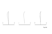
- Fig. 4a1 . Fig. 4a2 . Fig. 4b1 and Fig. 4b2 are Aberrationsdiagramme of transverse aberrations at the eyepiece image plane at low magnification with and without correction field lens shown.
- the underlying optical arrangements correspond to those in Fig. 3a and Fig. 3b shown.
- the aberration diagram Fig. 4a1 shows the transverse aberration in the tangential plane without correction field lens (cf. Fig. 3a ) and the aberration diagram Fig. 4a2 the transverse aberration in the tangential plane with correction field lens (cf. Fig. 3b ).
- a deviation range from the ideal state of -0.1 mm to + 0.1 mm is shown.
- the graph line shows the transverse aberration in the tangential plane for the wavelength 546 nm.
- the tangential image surface at each distance to the image center is affected by the correction field lens.
- the individual graphs are in the aberration diagram Fig. 4a2 each arranged flatter and closer to the horizontal, which describes an error-free ideal state, as in the aberration diagram Fig. 4a1 .
- the transverse aberration in the tangential plane is aberration diagram Fig. 4a2 , ie with correction field lens, significantly lower than aberration diagram Fig. 4a1 ,
- FIG. 4b1 shows the transverse aberration in the sagittal plane without correction field lens (cf. Fig. 3a ) and the aberration diagram Fig. 4b2 the transverse aberration in the sagittal plane with correction field lens (cf. Fig. 3b ).
- a deviation range from the ideal state of -0.1 mm to + 0.1 mm is shown.
- the graph line shows the transverse aberration in the sagittal plane for the wavelength 546 nm.
- the sagittal image surface is influenced by the correction field lens at every distance from the image field center.
- the individual graphs are in the aberration diagram Fig. 4b2 each arranged flatter and closer to the horizontal, which describes an error-free ideal state, as in the aberration diagram Fig. 4b1 .
- the transverse aberration in the sagittal plane is aberration diagram Fig. 4b2 , ie with correction field lens, significantly lower than aberration diagram Fig. 4b1 ,
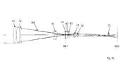
- Fig. 5a and Fig. 5b each describe an optical arrangement.
- a lens consisting of an objective lens 11 and two lens achromats 12, 13 and an eyepiece-side image plane BE2
- a reversing system is arranged between a lens, consisting of an objective lens 11 and two lens achromats 12, 13 and an eyepiece-side image plane BE2
- the inversion system has an objective-side field lens 50 and eyepiece-side two relatively movable optical elements 31, 32, wherein the second optical element 32 is arranged closer to the eyepiece-side image plane BE2 than the first optical element 31.
- Between the lens achromat 12 and the field lens 50 is a distance to the field lens 50 lens side image plane BE1.
- a reticle 41 is arranged in this image plane BE1 .
- Fig. 5b differs from Fig. 5a a correction field lens 40 according to the invention between the lens-side image plane BE1 and the field lens 50.
- she is cemented with the reticle 41.
- the displaceable optical elements 31, 32 are in a position where there is a large magnification. This can be seen on the basis of the beam paths SG such that the distance between the uppermost beam and the lowermost beam of the beam path SG in the eyepiece-side image plane BE2 is significantly greater than that between the uppermost beam and the lowermost beam of the beam path SG in the lens-side image plane BE1.
- Fig. 6a1 . Fig. 6a2 . Fig. 6b1 and Fig. 6b2 are Aberrationsdiagramme of transverse aberrations on the eyepiece image plane at high magnification with and without correction field lens shown.
- the underlying optical arrangements correspond to those in Fig. 5a and Fig. 5b shown.
- the aberration diagram Fig. 6a1 shows the transverse aberration in the tangential plane without correction field lens (cf. Fig. 5a ) and the aberration diagram Fig. 6a2 the transverse aberration in the tangential plane with correction field lens (cf. Fig. 5b ).
- the abscissa of each graph shows a deviation range from the ideal state of -0.2 mm to + 0.2 mm.
- the Graph line shows the transverse aberration in the tangential plane for the wavelength 546 nm.
- the tangential image surface at each distance to the image center is affected by the correction field lens.
- the individual graphs are in the aberration diagram Fig. 6a2 each arranged flatter and closer to the horizontal, which describes an error-free ideal state, as in the aberration diagram Fig. 6a1 .
- the transverse aberration in the tangential plane is aberration diagram Fig. 6a2 , ie with correction field lens, significantly lower than aberration diagram Fig. 6a1
- the improvements are not as blatant as with a small magnification according to Fig. 4a1 and Fig. 4a2 since the optical arrangement is already optimized for the medium to high magnifications, and the correction by the correction field lens at these magnifications is correspondingly lower.
- Fig. 6b1 shows the transverse aberration in the sagittal plane without correction field lens (cf. Fig. 5a ) and the aberration diagram Fig. 5b2 the transverse aberration in the sagittal plane with correction field lens (cf. Fig. 5b ).
- the abscissa of each graph shows a deviation range from the ideal state of -0.2 mm to + 0.2 mm.
- the graph line shows the transverse aberration in the sagittal plane for the wavelength 546 nm.
- the sagittal image surface is influenced by the correction field lens at every distance from the image field center.
- the individual graphs are in the aberration diagram Fig. 6b2 each arranged flatter and closer to the horizontal, which describes an error-free ideal state, as in the aberration diagram Fig. 6b1 .
- the transverse aberration in the sagittal plane is aberration diagram Fig. 6b2 , ie with correction field lens, significantly lower than aberration diagram Fig. 6b1 .
- the improvements are not so blatant as with a small magnification according to Fig. 4b1 and Fig. 4b2 since the optical arrangement is already optimized for the medium to high magnifications, and the correction by the correction field lens at these magnifications is correspondingly lower.
Landscapes
- Physics & Mathematics (AREA)
- Optics & Photonics (AREA)
- Engineering & Computer Science (AREA)
- General Engineering & Computer Science (AREA)
- Telescopes (AREA)
- Lenses (AREA)
Applications Claiming Priority (1)
| Application Number | Priority Date | Filing Date | Title |
|---|---|---|---|
| DE102011000685A DE102011000685B3 (de) | 2011-02-11 | 2011-02-11 | Zielfernrohr mit Korrekturfeldlinse |
Publications (3)
| Publication Number | Publication Date |
|---|---|
| EP2487449A2 true EP2487449A2 (fr) | 2012-08-15 |
| EP2487449A3 EP2487449A3 (fr) | 2015-05-20 |
| EP2487449B1 EP2487449B1 (fr) | 2020-04-01 |
Family
ID=45655592
Family Applications (1)
| Application Number | Title | Priority Date | Filing Date |
|---|---|---|---|
| EP12154951.3A Active EP2487449B1 (fr) | 2011-02-11 | 2012-02-10 | Lunette de visée dotée d'une lentille de correction de champ |
Country Status (3)
| Country | Link |
|---|---|
| US (1) | US8958149B2 (fr) |
| EP (1) | EP2487449B1 (fr) |
| DE (1) | DE102011000685B3 (fr) |
Cited By (1)
| Publication number | Priority date | Publication date | Assignee | Title |
|---|---|---|---|---|
| CZ304284B6 (cs) * | 2013-02-21 | 2014-02-12 | ÄŚeskĂ© vysokĂ© uÄŤenĂ technickĂ© v Praze - fakulta stavebnĂ | Puškohled s proměnným zvětšením |
Families Citing this family (1)
| Publication number | Priority date | Publication date | Assignee | Title |
|---|---|---|---|---|
| AT513009B1 (de) * | 2012-06-11 | 2021-02-15 | Swarovski Optik Kg | Objektiv für ein Bildaufzeichnungsgerät |
Citations (2)
| Publication number | Priority date | Publication date | Assignee | Title |
|---|---|---|---|---|
| US7684114B2 (en) | 2005-01-26 | 2010-03-23 | Leupold & Stevens, Inc. | Scope with improved magnification system |
| EP1746451B1 (fr) | 2005-07-20 | 2010-06-09 | Swarovski-Optik KG | Lunette de visée à grand champ et grossissement variable |
Family Cites Families (8)
| Publication number | Priority date | Publication date | Assignee | Title |
|---|---|---|---|---|
| US3045545A (en) * | 1960-11-10 | 1962-07-24 | Bausch & Lomb | Optical system for sighting instruments |
| US3918791A (en) * | 1974-10-18 | 1975-11-11 | Leupold & Stevens Inc | Flat field variable power rifle scope |
| US4497548A (en) * | 1980-12-05 | 1985-02-05 | Burris Company | Variable-power riflescope with range-compensating reticle and a field stop diaphram centered off the optical axis |
| AT394457B (de) * | 1985-12-18 | 1992-04-10 | Basta Walter | Zielfernrohr mit automatischer elevationseinrichtung fuer scharfschuetzengewehre |
| US5481405A (en) * | 1993-11-30 | 1996-01-02 | Minnesota Mining And Manufacturing Company | Stepless micrographic zoom lens having large magnification ratio |
| DE10116997A1 (de) * | 2001-04-05 | 2002-10-31 | Hensoldt & Soehne Optik | Zielfernrohr |
| EP1817538B1 (fr) * | 2004-11-30 | 2013-03-27 | Bernard Thomas Windauer | Systeme de visee optique |
| DE102005063245A1 (de) * | 2005-12-21 | 2007-07-05 | Carl Zeiss Sports Optics Gmbh | Fernrohr mit variabler Vergrößerung |
-
2011
- 2011-02-11 DE DE102011000685A patent/DE102011000685B3/de active Active
-
2012
- 2012-02-10 US US13/370,749 patent/US8958149B2/en active Active
- 2012-02-10 EP EP12154951.3A patent/EP2487449B1/fr active Active
Patent Citations (2)
| Publication number | Priority date | Publication date | Assignee | Title |
|---|---|---|---|---|
| US7684114B2 (en) | 2005-01-26 | 2010-03-23 | Leupold & Stevens, Inc. | Scope with improved magnification system |
| EP1746451B1 (fr) | 2005-07-20 | 2010-06-09 | Swarovski-Optik KG | Lunette de visée à grand champ et grossissement variable |
Cited By (1)
| Publication number | Priority date | Publication date | Assignee | Title |
|---|---|---|---|---|
| CZ304284B6 (cs) * | 2013-02-21 | 2014-02-12 | ÄŚeskĂ© vysokĂ© uÄŤenĂ technickĂ© v Praze - fakulta stavebnĂ | Puškohled s proměnným zvětšením |
Also Published As
| Publication number | Publication date |
|---|---|
| EP2487449A3 (fr) | 2015-05-20 |
| US20120212811A1 (en) | 2012-08-23 |
| EP2487449B1 (fr) | 2020-04-01 |
| US8958149B2 (en) | 2015-02-17 |
| DE102011000685B3 (de) | 2012-08-09 |
Similar Documents
| Publication | Publication Date | Title |
|---|---|---|
| DE19858785C2 (de) | Endoskopobjektiv sowie Endoskop mit einem derartigen Objektiv | |
| EP3420882B1 (fr) | Objectif de caméra pour un endoscope et endoscope | |
| DE102013105425B3 (de) | Fotografisches Weitwinkelobjektiv mit Innenfokussierung | |
| DE69809880T2 (de) | Objektiv mit konstanter brennweite im sichtbaren- und im ir-bereich | |
| DE112017003378T5 (de) | Endoskopoptik | |
| DE102015201393B4 (de) | Anordnung zur Fokusveränderung eines Mikroskopobjektivs | |
| DE69629301T2 (de) | Tripletobjektiv mit fester brennweite für overheadprojektoren | |
| DE102007005168A1 (de) | Anastigmatisches anamorphotisches Objektiv | |
| EP2211222B1 (fr) | Lunette de visée à grand champ et grossissement élevé | |
| DE102015218328A1 (de) | Optisches System zur Feldabbildung und/oder Pupillenabbildung | |
| DE102004003139A1 (de) | Polarausrichtungsteil variabler Brennweite | |
| DE102011000685B3 (de) | Zielfernrohr mit Korrekturfeldlinse | |
| DE4401364A1 (de) | Realbildsucher | |
| WO2007140747A1 (fr) | Oculaire de télescope avec pupille de sortie très éloignée | |
| DE102018106236B3 (de) | Objektiv mit fester Brennweite | |
| EP2495599B1 (fr) | Lunette de visée dotée d'une pupille de sortie agrandie | |
| DE102010015506A1 (de) | Katadioptrisches Cassegrain-Objektiv | |
| DE102007046505A1 (de) | Anzeigevorrichtung | |
| DE102018204155B4 (de) | Objektiv mit veränderlicher Brennweite und Verfahren zur Steuerung des Objektivs sowie Fernrohr und Fernglas mit einem solchen Objektiv | |
| DE19930568A1 (de) | Nahvorsatzoptik für ein Binokular | |
| DE102019211360A1 (de) | Tubussystem | |
| DE19964079C1 (de) | Maksutov-Cassegrain-System kurzer Baulänge | |
| EP1403679B1 (fr) | Oculaire | |
| DE7041703U (de) | Optisches System stufenlos verander barer Vergrosserung | |
| DE102013110423A1 (de) | Endoskop |
Legal Events
| Date | Code | Title | Description |
|---|---|---|---|
| PUAI | Public reference made under article 153(3) epc to a published international application that has entered the european phase |
Free format text: ORIGINAL CODE: 0009012 |
|
| AK | Designated contracting states |
Kind code of ref document: A2 Designated state(s): AL AT BE BG CH CY CZ DE DK EE ES FI FR GB GR HR HU IE IS IT LI LT LU LV MC MK MT NL NO PL PT RO RS SE SI SK SM TR |
|
| AX | Request for extension of the european patent |
Extension state: BA ME |
|
| PUAL | Search report despatched |
Free format text: ORIGINAL CODE: 0009013 |
|
| AK | Designated contracting states |
Kind code of ref document: A3 Designated state(s): AL AT BE BG CH CY CZ DE DK EE ES FI FR GB GR HR HU IE IS IT LI LT LU LV MC MK MT NL NO PL PT RO RS SE SI SK SM TR |
|
| AX | Request for extension of the european patent |
Extension state: BA ME |
|
| RIC1 | Information provided on ipc code assigned before grant |
Ipc: F41G 1/38 20060101AFI20150415BHEP |
|
| 17P | Request for examination filed |
Effective date: 20151113 |
|
| RBV | Designated contracting states (corrected) |
Designated state(s): AL AT BE BG CH CY CZ DE DK EE ES FI FR GB GR HR HU IE IS IT LI LT LU LV MC MK MT NL NO PL PT RO RS SE SI SK SM TR |
|
| GRAP | Despatch of communication of intention to grant a patent |
Free format text: ORIGINAL CODE: EPIDOSNIGR1 |
|
| STAA | Information on the status of an ep patent application or granted ep patent |
Free format text: STATUS: GRANT OF PATENT IS INTENDED |
|
| INTG | Intention to grant announced |
Effective date: 20191004 |
|
| GRAS | Grant fee paid |
Free format text: ORIGINAL CODE: EPIDOSNIGR3 |
|
| GRAA | (expected) grant |
Free format text: ORIGINAL CODE: 0009210 |
|
| STAA | Information on the status of an ep patent application or granted ep patent |
Free format text: STATUS: THE PATENT HAS BEEN GRANTED |
|
| AK | Designated contracting states |
Kind code of ref document: B1 Designated state(s): AL AT BE BG CH CY CZ DE DK EE ES FI FR GB GR HR HU IE IS IT LI LT LU LV MC MK MT NL NO PL PT RO RS SE SI SK SM TR |
|
| REG | Reference to a national code |
Ref country code: GB Ref legal event code: FG4D Free format text: NOT ENGLISH |
|
| REG | Reference to a national code |
Ref country code: AT Ref legal event code: REF Ref document number: 1251902 Country of ref document: AT Kind code of ref document: T Effective date: 20200415 Ref country code: CH Ref legal event code: EP |
|
| REG | Reference to a national code |
Ref country code: DE Ref legal event code: R096 Ref document number: 502012015909 Country of ref document: DE |
|
| REG | Reference to a national code |
Ref country code: IE Ref legal event code: FG4D Free format text: LANGUAGE OF EP DOCUMENT: GERMAN |
|
| PG25 | Lapsed in a contracting state [announced via postgrant information from national office to epo] |
Ref country code: BG Free format text: LAPSE BECAUSE OF FAILURE TO SUBMIT A TRANSLATION OF THE DESCRIPTION OR TO PAY THE FEE WITHIN THE PRESCRIBED TIME-LIMIT Effective date: 20200701 |
|
| REG | Reference to a national code |
Ref country code: NL Ref legal event code: MP Effective date: 20200401 |
|
| REG | Reference to a national code |
Ref country code: LT Ref legal event code: MG4D |
|
| PG25 | Lapsed in a contracting state [announced via postgrant information from national office to epo] |
Ref country code: NO Free format text: LAPSE BECAUSE OF FAILURE TO SUBMIT A TRANSLATION OF THE DESCRIPTION OR TO PAY THE FEE WITHIN THE PRESCRIBED TIME-LIMIT Effective date: 20200701 Ref country code: IS Free format text: LAPSE BECAUSE OF FAILURE TO SUBMIT A TRANSLATION OF THE DESCRIPTION OR TO PAY THE FEE WITHIN THE PRESCRIBED TIME-LIMIT Effective date: 20200801 Ref country code: GR Free format text: LAPSE BECAUSE OF FAILURE TO SUBMIT A TRANSLATION OF THE DESCRIPTION OR TO PAY THE FEE WITHIN THE PRESCRIBED TIME-LIMIT Effective date: 20200702 Ref country code: NL Free format text: LAPSE BECAUSE OF FAILURE TO SUBMIT A TRANSLATION OF THE DESCRIPTION OR TO PAY THE FEE WITHIN THE PRESCRIBED TIME-LIMIT Effective date: 20200401 Ref country code: SE Free format text: LAPSE BECAUSE OF FAILURE TO SUBMIT A TRANSLATION OF THE DESCRIPTION OR TO PAY THE FEE WITHIN THE PRESCRIBED TIME-LIMIT Effective date: 20200401 Ref country code: LT Free format text: LAPSE BECAUSE OF FAILURE TO SUBMIT A TRANSLATION OF THE DESCRIPTION OR TO PAY THE FEE WITHIN THE PRESCRIBED TIME-LIMIT Effective date: 20200401 Ref country code: PT Free format text: LAPSE BECAUSE OF FAILURE TO SUBMIT A TRANSLATION OF THE DESCRIPTION OR TO PAY THE FEE WITHIN THE PRESCRIBED TIME-LIMIT Effective date: 20200817 Ref country code: FI Free format text: LAPSE BECAUSE OF FAILURE TO SUBMIT A TRANSLATION OF THE DESCRIPTION OR TO PAY THE FEE WITHIN THE PRESCRIBED TIME-LIMIT Effective date: 20200401 Ref country code: CZ Free format text: LAPSE BECAUSE OF FAILURE TO SUBMIT A TRANSLATION OF THE DESCRIPTION OR TO PAY THE FEE WITHIN THE PRESCRIBED TIME-LIMIT Effective date: 20200401 |
|
| PG25 | Lapsed in a contracting state [announced via postgrant information from national office to epo] |
Ref country code: LV Free format text: LAPSE BECAUSE OF FAILURE TO SUBMIT A TRANSLATION OF THE DESCRIPTION OR TO PAY THE FEE WITHIN THE PRESCRIBED TIME-LIMIT Effective date: 20200401 Ref country code: HR Free format text: LAPSE BECAUSE OF FAILURE TO SUBMIT A TRANSLATION OF THE DESCRIPTION OR TO PAY THE FEE WITHIN THE PRESCRIBED TIME-LIMIT Effective date: 20200401 Ref country code: RS Free format text: LAPSE BECAUSE OF FAILURE TO SUBMIT A TRANSLATION OF THE DESCRIPTION OR TO PAY THE FEE WITHIN THE PRESCRIBED TIME-LIMIT Effective date: 20200401 |
|
| PG25 | Lapsed in a contracting state [announced via postgrant information from national office to epo] |
Ref country code: AL Free format text: LAPSE BECAUSE OF FAILURE TO SUBMIT A TRANSLATION OF THE DESCRIPTION OR TO PAY THE FEE WITHIN THE PRESCRIBED TIME-LIMIT Effective date: 20200401 |
|
| REG | Reference to a national code |
Ref country code: DE Ref legal event code: R097 Ref document number: 502012015909 Country of ref document: DE |
|
| PG25 | Lapsed in a contracting state [announced via postgrant information from national office to epo] |
Ref country code: RO Free format text: LAPSE BECAUSE OF FAILURE TO SUBMIT A TRANSLATION OF THE DESCRIPTION OR TO PAY THE FEE WITHIN THE PRESCRIBED TIME-LIMIT Effective date: 20200401 Ref country code: IT Free format text: LAPSE BECAUSE OF FAILURE TO SUBMIT A TRANSLATION OF THE DESCRIPTION OR TO PAY THE FEE WITHIN THE PRESCRIBED TIME-LIMIT Effective date: 20200401 Ref country code: ES Free format text: LAPSE BECAUSE OF FAILURE TO SUBMIT A TRANSLATION OF THE DESCRIPTION OR TO PAY THE FEE WITHIN THE PRESCRIBED TIME-LIMIT Effective date: 20200401 Ref country code: SM Free format text: LAPSE BECAUSE OF FAILURE TO SUBMIT A TRANSLATION OF THE DESCRIPTION OR TO PAY THE FEE WITHIN THE PRESCRIBED TIME-LIMIT Effective date: 20200401 Ref country code: EE Free format text: LAPSE BECAUSE OF FAILURE TO SUBMIT A TRANSLATION OF THE DESCRIPTION OR TO PAY THE FEE WITHIN THE PRESCRIBED TIME-LIMIT Effective date: 20200401 Ref country code: DK Free format text: LAPSE BECAUSE OF FAILURE TO SUBMIT A TRANSLATION OF THE DESCRIPTION OR TO PAY THE FEE WITHIN THE PRESCRIBED TIME-LIMIT Effective date: 20200401 |
|
| PLBE | No opposition filed within time limit |
Free format text: ORIGINAL CODE: 0009261 |
|
| STAA | Information on the status of an ep patent application or granted ep patent |
Free format text: STATUS: NO OPPOSITION FILED WITHIN TIME LIMIT |
|
| PG25 | Lapsed in a contracting state [announced via postgrant information from national office to epo] |
Ref country code: PL Free format text: LAPSE BECAUSE OF FAILURE TO SUBMIT A TRANSLATION OF THE DESCRIPTION OR TO PAY THE FEE WITHIN THE PRESCRIBED TIME-LIMIT Effective date: 20200401 Ref country code: SK Free format text: LAPSE BECAUSE OF FAILURE TO SUBMIT A TRANSLATION OF THE DESCRIPTION OR TO PAY THE FEE WITHIN THE PRESCRIBED TIME-LIMIT Effective date: 20200401 |
|
| 26N | No opposition filed |
Effective date: 20210112 |
|
| PG25 | Lapsed in a contracting state [announced via postgrant information from national office to epo] |
Ref country code: SI Free format text: LAPSE BECAUSE OF FAILURE TO SUBMIT A TRANSLATION OF THE DESCRIPTION OR TO PAY THE FEE WITHIN THE PRESCRIBED TIME-LIMIT Effective date: 20200401 |
|
| PG25 | Lapsed in a contracting state [announced via postgrant information from national office to epo] |
Ref country code: MC Free format text: LAPSE BECAUSE OF FAILURE TO SUBMIT A TRANSLATION OF THE DESCRIPTION OR TO PAY THE FEE WITHIN THE PRESCRIBED TIME-LIMIT Effective date: 20200401 |
|
| REG | Reference to a national code |
Ref country code: BE Ref legal event code: MM Effective date: 20210228 |
|
| PG25 | Lapsed in a contracting state [announced via postgrant information from national office to epo] |
Ref country code: LI Free format text: LAPSE BECAUSE OF NON-PAYMENT OF DUE FEES Effective date: 20210228 Ref country code: LU Free format text: LAPSE BECAUSE OF NON-PAYMENT OF DUE FEES Effective date: 20210210 Ref country code: CH Free format text: LAPSE BECAUSE OF NON-PAYMENT OF DUE FEES Effective date: 20210228 |
|
| PG25 | Lapsed in a contracting state [announced via postgrant information from national office to epo] |
Ref country code: IE Free format text: LAPSE BECAUSE OF NON-PAYMENT OF DUE FEES Effective date: 20210210 |
|
| REG | Reference to a national code |
Ref country code: AT Ref legal event code: MM01 Ref document number: 1251902 Country of ref document: AT Kind code of ref document: T Effective date: 20210210 |
|
| PG25 | Lapsed in a contracting state [announced via postgrant information from national office to epo] |
Ref country code: AT Free format text: LAPSE BECAUSE OF NON-PAYMENT OF DUE FEES Effective date: 20210210 |
|
| PG25 | Lapsed in a contracting state [announced via postgrant information from national office to epo] |
Ref country code: BE Free format text: LAPSE BECAUSE OF NON-PAYMENT OF DUE FEES Effective date: 20210228 |
|
| PG25 | Lapsed in a contracting state [announced via postgrant information from national office to epo] |
Ref country code: HU Free format text: LAPSE BECAUSE OF FAILURE TO SUBMIT A TRANSLATION OF THE DESCRIPTION OR TO PAY THE FEE WITHIN THE PRESCRIBED TIME-LIMIT; INVALID AB INITIO Effective date: 20120210 Ref country code: CY Free format text: LAPSE BECAUSE OF FAILURE TO SUBMIT A TRANSLATION OF THE DESCRIPTION OR TO PAY THE FEE WITHIN THE PRESCRIBED TIME-LIMIT Effective date: 20200401 |
|
| PG25 | Lapsed in a contracting state [announced via postgrant information from national office to epo] |
Ref country code: MK Free format text: LAPSE BECAUSE OF FAILURE TO SUBMIT A TRANSLATION OF THE DESCRIPTION OR TO PAY THE FEE WITHIN THE PRESCRIBED TIME-LIMIT Effective date: 20200401 |
|
| PG25 | Lapsed in a contracting state [announced via postgrant information from national office to epo] |
Ref country code: TR Free format text: LAPSE BECAUSE OF FAILURE TO SUBMIT A TRANSLATION OF THE DESCRIPTION OR TO PAY THE FEE WITHIN THE PRESCRIBED TIME-LIMIT Effective date: 20200401 |
|
| PG25 | Lapsed in a contracting state [announced via postgrant information from national office to epo] |
Ref country code: MT Free format text: LAPSE BECAUSE OF FAILURE TO SUBMIT A TRANSLATION OF THE DESCRIPTION OR TO PAY THE FEE WITHIN THE PRESCRIBED TIME-LIMIT Effective date: 20200401 |
|
| PGFP | Annual fee paid to national office [announced via postgrant information from national office to epo] |
Ref country code: GB Payment date: 20260219 Year of fee payment: 15 |
|
| PGFP | Annual fee paid to national office [announced via postgrant information from national office to epo] |
Ref country code: DE Payment date: 20260228 Year of fee payment: 15 |
|
| PGFP | Annual fee paid to national office [announced via postgrant information from national office to epo] |
Ref country code: FR Payment date: 20260218 Year of fee payment: 15 |