EP2487465A1 - Structure de capteur - Google Patents
Structure de capteur Download PDFInfo
- Publication number
- EP2487465A1 EP2487465A1 EP12154740A EP12154740A EP2487465A1 EP 2487465 A1 EP2487465 A1 EP 2487465A1 EP 12154740 A EP12154740 A EP 12154740A EP 12154740 A EP12154740 A EP 12154740A EP 2487465 A1 EP2487465 A1 EP 2487465A1
- Authority
- EP
- European Patent Office
- Prior art keywords
- pressure
- measurement device
- intake air
- structural component
- sensor
- Prior art date
- Legal status (The legal status is an assumption and is not a legal conclusion. Google has not performed a legal analysis and makes no representation as to the accuracy of the status listed.)
- Granted
Links
Images



Classifications
-
- G—PHYSICS
- G01—MEASURING; TESTING
- G01F—MEASURING VOLUME, VOLUME FLOW, MASS FLOW OR LIQUID LEVEL; METERING BY VOLUME
- G01F1/00—Measuring the volume flow or mass flow of fluid or fluent solid material wherein the fluid passes through a meter in a continuous flow
- G01F1/68—Measuring the volume flow or mass flow of fluid or fluent solid material wherein the fluid passes through a meter in a continuous flow by using thermal effects
- G01F1/684—Structural arrangements; Mounting of elements, e.g. in relation to fluid flow
-
- G—PHYSICS
- G01—MEASURING; TESTING
- G01L—MEASURING FORCE, STRESS, TORQUE, WORK, MECHANICAL POWER, MECHANICAL EFFICIENCY, OR FLUID PRESSURE
- G01L19/00—Details of, or accessories for, apparatus for measuring steady or quasi-steady pressure of a fluent medium insofar as such details or accessories are not special to particular types of pressure gauges
- G01L19/0007—Fluidic connecting means
-
- G—PHYSICS
- G01—MEASURING; TESTING
- G01L—MEASURING FORCE, STRESS, TORQUE, WORK, MECHANICAL POWER, MECHANICAL EFFICIENCY, OR FLUID PRESSURE
- G01L23/00—Devices or apparatus for measuring or indicating or recording rapid changes, such as oscillations, in the pressure of steam, gas, or liquid; Indicators for determining work or energy of steam, internal-combustion, or other fluid-pressure engines from the condition of the working fluid
- G01L23/24—Devices or apparatus for measuring or indicating or recording rapid changes, such as oscillations, in the pressure of steam, gas, or liquid; Indicators for determining work or energy of steam, internal-combustion, or other fluid-pressure engines from the condition of the working fluid specially adapted for measuring pressure in inlet or exhaust ducts of internal-combustion engines
Definitions
- the present invention relates to a sensor structure suitable for measuring a physical quantity of intake air in an internal combustion engine, and to an internal combustion engine controller using the same.
- a typical pressure measurement device for measuring pressure in an intake air tube includes a pressure measurement part formed of a semiconductor and a pressure intake tube (see JP Patent Application Publication No. 2006-292391 A ).
- a heating resistor type mass airflow measurement device As an air mass flow measurement technology for an internal combustion engine, a heating resistor type mass airflow measurement device is known (see JP Patent No. 3523022 B ). This device takes advantages of the fact that an amount of heat that a heating resistor is deprived of is in correlation with an amount of intake air flow and is capable of directly measuring an air mass flow required for controlling combustion of an engine, and is therefore widely used especially as a flowmeter for controlling an air-fuel ratio in an automobile.
- Such a heating resistor type mass airflow measurement device may be integrated with the pressure measurement device (see JP Patent Application Publication No. 2008-304232 A ).
- An automobile using an electronically controlled fuel injection system has been commonly used. In recent years, it has been developed for achieving higher performance and higher functionality. It is desirable to reduce the number of components and improve the appearance inside an engine room by integrating a plurality of sensors and control equipment with each other. As an example, a mass airflow measurement device is integrated with a pressure measurement device so that connectors can be used in common, thereby reducing the number of process steps for assembling components into an automobile and simplifying a wiring harness.
- the pressure measurement device In an engine control system in which a single pressure measurement device is disposed on upstream of a throttle valve, for example, in an intake air tube, the pressure measurement device is required to measure pressure while air flows. Accordingly, a sensor structure needs to be provided such that a dynamic pressure effect caused by airflow is avoided as much as possible.
- a pressure measurement device is integrated with a mass airflow measurement device and a pressure intake port is defined by a part of a housing structural component making up a skeleton of the mass airflow measurement device, the mass airflow measurement device is disposed at a position where intake air in an engine flows. Accordingly, a sensor structure for measuring pressure also needs to be provided such that a dynamic pressure effect caused by airflow is avoided as much as possible.
- the pressure intake port can be opened inside or in the middle of an insertion hole on the sensor provided in the intake air tube to avoid the dynamic pressure effect caused by the airflow.
- the molding dimensional precision of an air cleaner or the like making up the intake air tube is not so high and the positional relationship between the mounting position of the sensor and the position of the insertion hole on the sensor is easily varied.
- an opening portion of the pressure intake port may be brought into contact with the side wall of the insertion hole on the sensor and the sensitivity of pressure measurement may be reduced.
- An object of the present invention which is aimed at solving the problems mentioned above, is to provide a sensor structure for stably measuring pressure even when a pressure intake port is brought into contact with a side wall of an insertion hole on a sensor in integrating a mass airflow measurement device with a pressure measurement device, and for preventing contaminated substances, water droplets, or the like from arriving at a pressure measurement part of the pressure measurement device.
- a sensor structure including: a mass airflow measurement device inserted into a sensor insertion port provided in an intake air tube component including an intake air tube and fixed to the intake air tube; and/or a pressure measurement device mounted in a housing structural component of the mass airflow measurement device for measuring pressure inside the intake tube, wherein a pressure intake port connecting the pressure measurement device to an inside of the intake air tube is provided in the housing structural component, an opening portion of the pressure intake port is provided on a side face of the housing structural component, and/or a cross-sectional area of the opening portion is larger than a cross-sectional area of the pressure intake port.
- a sensor structure for stably measuring pressure even when a pressure intake port is brought into contact with a side wall of an insertion hole on a sensor in integrating a mass airflow measurement device with a pressure measurement device, and for preventing contaminated substances, water droplets, or the like from arriving at a pressure measurement part of the pressure measurement device can be provided.
- FIG. 1 A specific structure example of the present invention will be explained with reference to FIG. 1 .
- a main air flow passage component 2 forming a main air flow passage 1 includes an insertion port 4 into which a part of a multifunction sensor 64, which is provided by integrating a pressure measurement device 3 with a mass airflow measurement device 16, is inserted via a gasket 5.
- the skeleton of the mass airflow measurement device 16 is formed using a housing structural component 6, a base plate 17, an electronic circuit board 18, a cover 19, a heating resistor 20 for measuring an air mass flow, a temperature compensation resistor 21 used for measuring the air mass flow, an intake air temperature sensor 22 used on a side close to a vehicle, a bypass air passage 23 including a measurement element for measuring the air mass flow and temperature, and a bypass air passage structural component 24 forming the bypass air passage 23.
- the heating resistor 20 for detecting the air mass flow and temperature of intake air, the temperature compensation resistor 21, and the intake air temperature sensor 22 are connected to the electronic circuit board 18 via a bonding wire 25.
- the electronic circuit board 18 is electrically connected to a connector terminal 9 via the bonding wire 25 to perform an input/output from/to the outside via an I/O connector 10.
- the basic structure of the integrated pressure measurement device 3 is formed by the housing structural component 6.
- a sensor chip 7 having a pressure measurement part is mounted on the housing structural component 6, and is fixed and sealed by a sealing agent 8 such as an adhesive agent.
- the sensor chip 7 is electrically connected to the connector terminal 9 by means of bonding, welding, or the like to perform an input/output from/to the outside via the I/O connector 10 as well as the mass airflow measurement device 16.
- the housing structural component 6 includes a pressure intake port 11 connecting the sensor chip 7 to the main air flow passage 1 for measuring the pressure inside an intake air tube using the pressure intake port 11.
- the pressure intake port 11 has a cross-sectional area expanded at a position close to the main air flow passage 1, and forms an enlarged opening 12 having an area vertically expanded in the air-flowing direction.
- the enlarged opening 12 is disposed on the side face of the housing structural component 6.
- the pressure measurement device 3 Since air flows in the main air flow passage 1, the pressure measurement device 3 needs to measure the pressure while the air flows.
- the dynamic pressure effect caused by airflow and the drift effect caused by twist of the tube or the air cleaner exist inside the intake air tube in the automobile, and accordingly, it is required to avoid such effects.
- the enlarged opening 12 is disposed on the side face of the housing structural component 6 and is formed to be long in the air-flowing direction. Due to such a structure, the pressure can be taken in from a wide range so as to be equalized and measured.
- FIG. 2 is a structural diagram of a sensor according to another embodiment of the present invention and its cross sectional view taken along the line B-B.
- intake air is sucked in after air suspended substances are removed by an air filter element provided in an air cleaner box.
- a large pressure loss caused by the air filter element which involves the engine output reduction and the fuel consumption rate deterioration, is not desired, and therefore a filter capable of filtering fine carbon and the like contained in exhaust gas is not used. Accordingly, fine air suspended substances or rain water are sucked into the engine through the filter.
- the enlarged opening 12 of the pressure intake port is disposed on an outer side compared to an inner wall surface 13 of the main air flow passage component 2.
- the enlarged opening 12 of the pressure intake port is disposed on a position opposite to the wall surface forming the sensor insertion port 4. Due to such a structure, the possibility of sucking contaminated substances and water droplets is considerably reduced. Also, since the enlarged opening 12 and the pressure intake port 11 are not directly exposed to the airflow, the dynamic pressure effect caused by the airflow and the drift effect can be reduced.
- the main air flow passage component 2 usually corresponds to a resin-molded air cleaner in the automobile, the molding dimensional precision of which is not so high.
- the multifunction sensor 64 is attached and fixed to the air cleaner by a screw, a positional relationship between the insertion port 4 and a screw hole is easily varied. Consequently, the pressure intake port 11 is brought into contact with the side wall of the insertion port 4 when the pressure intake port 11 is disposed on the side face of the housing structural component 6, which may unfavorably affect the pressure measurement and sensitivity.
- the enlarged opening 12 as shown in FIG. 2 , the possibility that the enlarged opening 12 is completely closed is almost zero even when being brought into contact with the side wall of the insertion port 4 because its opening portion is enlarged. Therefore, a pressure measurement function can be always maintained.
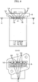
- FIG. 3 is a structural diagram of a sensor according to another embodiment of the present invention and its cross sectional view taken along the line C-C.
- the enlarged opening 12 unfavorably guides water droplets or the like to the pressure intake port 11 when the water droplets or the like are delivered into the enlarged opening 12.
- partition walls 14 are provided in the enlarged opening 12 to divide the enlarged opening 12 into a plurality of blocks.
- the partition walls 14 are provided to be lower than the outer wall surface of the housing structural component 6.
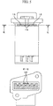
- FIG. 4 is a structural diagram of a sensor according to another embodiment of the present invention and its cross sectional view taken along the line D-D.
- the upper surface of each partition wall 14 has the same height as the outer wall surface of the housing structural component 6.
- Communication grooves 15 are provided only on the upper surfaces of the partition walls 14 which partition the enlarged opening 12 so as to enable the pressure measurement.
- FIG. 5 is a structural diagram of a sensor according to another embodiment of the present invention and its cross sectional view taken along the line E-E.
- the adjacent communication grooves 15 are staggeredly arranged in the structure shown in FIG. 5 compared to the structure as shown in FIG. 4 to further resist the moving of water droplets.
- FIG. 6 illustrates an internal combustion engine of an electronic fuel injection type to which another embodiment of the present invention is applied.
- An intake air 51 sucked by an air cleaner 50 is sucked into an engine cylinder 56 through an intake manifold 55 including the main air flow passage component 2 to which the multifunction sensor 64 is inserted, an intake air duct 52, a throttle body 53, and a fuel injector 54 to which fuel is supplied.
- a gas 57 generated in the engine cylinder 56 is discharged through an exhaust manifold 58.
- An engine control unit 62 inputs an air mass flow signal, a humidity signal, a pressure signal, and a temperature signal outputted from the multifunction sensor 64, a throttle valve angle signal outputted from a throttle angle sensor 59, an oxygen concentration signal outputted from an oxygen meter 60 provided in the exhaust manifold 58, and an engine rotational speed signal outputted from an engine speed meter 61, and calculates an optimal fuel injection amount and an optimal output torque. Such values are used to control the fuel injector 54 and the throttle valve 63.
Landscapes
- Physics & Mathematics (AREA)
- General Physics & Mathematics (AREA)
- Chemical & Material Sciences (AREA)
- Engineering & Computer Science (AREA)
- Combustion & Propulsion (AREA)
- Fluid Mechanics (AREA)
- Measuring Volume Flow (AREA)
- Measuring Fluid Pressure (AREA)
Applications Claiming Priority (1)
| Application Number | Priority Date | Filing Date | Title |
|---|---|---|---|
| JP2011025556A JP5557767B2 (ja) | 2011-02-09 | 2011-02-09 | センサの構造 |
Publications (2)
| Publication Number | Publication Date |
|---|---|
| EP2487465A1 true EP2487465A1 (fr) | 2012-08-15 |
| EP2487465B1 EP2487465B1 (fr) | 2019-12-18 |
Family
ID=45655535
Family Applications (1)
| Application Number | Title | Priority Date | Filing Date |
|---|---|---|---|
| EP12154740.0A Active EP2487465B1 (fr) | 2011-02-09 | 2012-02-09 | Structure de capteur |
Country Status (4)
| Country | Link |
|---|---|
| US (1) | US20120198943A1 (fr) |
| EP (1) | EP2487465B1 (fr) |
| JP (1) | JP5557767B2 (fr) |
| CN (1) | CN102636227B (fr) |
Families Citing this family (13)
| Publication number | Priority date | Publication date | Assignee | Title |
|---|---|---|---|---|
| KR101748875B1 (ko) * | 2010-08-20 | 2017-06-19 | 두산인프라코어 주식회사 | 전자식 터보차저 엔진의 부스트 압력센서 장착용 어댑터 구조 |
| JP2012052809A (ja) * | 2010-08-31 | 2012-03-15 | Hitachi Automotive Systems Ltd | センサの構造 |
| JP5675717B2 (ja) * | 2012-06-29 | 2015-02-25 | 日立オートモティブシステムズ株式会社 | 空気物理量検出装置 |
| US9588003B2 (en) * | 2013-09-26 | 2017-03-07 | Rosemount Inc. | Isolator system for a pressure transmitter |
| JP6387953B2 (ja) * | 2015-12-22 | 2018-09-12 | 株式会社デンソー | 空気流量測定装置 |
| WO2017156174A1 (fr) | 2016-03-08 | 2017-09-14 | K&N Engineering, Inc. | Système et procédé d'admission d'air de chargeur d'air |
| US10718300B2 (en) | 2016-03-09 | 2020-07-21 | K&N Engineering, Inc. | High performance air intake system |
| JP6578238B2 (ja) * | 2016-04-11 | 2019-09-18 | 日立オートモティブシステムズ株式会社 | 物理量検出装置 |
| CN107655798B (zh) * | 2016-07-26 | 2024-04-09 | 惠州华阳通用电子有限公司 | 一种检测汽车内外空气质量的装置 |
| WO2018193743A1 (fr) * | 2017-04-21 | 2018-10-25 | 日立オートモティブシステムズ株式会社 | Dispositif de mesure de température |
| JP6965358B2 (ja) * | 2017-09-05 | 2021-11-10 | 日立Astemo株式会社 | 熱式流量計 |
| CN108412648A (zh) * | 2018-04-16 | 2018-08-17 | 浙江毅力汽车空调有限公司 | 一种智能汽车超微进气传感调控器 |
| US11480451B2 (en) | 2018-12-17 | 2022-10-25 | Waymo Llc | Integrated cooling solution for spinning sensors |
Citations (7)
| Publication number | Priority date | Publication date | Assignee | Title |
|---|---|---|---|---|
| US4215565A (en) * | 1977-09-01 | 1980-08-05 | Agar Instrumentation Inc. | Method and apparatus for testing a fluid |
| DE4317312A1 (de) * | 1993-05-25 | 1994-12-01 | Bosch Gmbh Robert | Drucksensor in einem Kunststoffgehäuse und Verfahren zur Herstellung |
| DE19711939A1 (de) * | 1997-03-21 | 1998-09-24 | Bosch Gmbh Robert | Vorrichtung zur Erfassung des Drucks und der Temperatur im Saugrohr einer Brennkraftmaschine |
| JP3523022B2 (ja) | 1997-06-26 | 2004-04-26 | 株式会社日立製作所 | 発熱抵抗体式空気流量測定装置及び内燃機関の吸気系システム及び内燃機関の制御システム |
| JP2006292391A (ja) | 2005-04-06 | 2006-10-26 | Hitachi Ltd | 圧力検出装置 |
| JP2008304232A (ja) | 2007-06-06 | 2008-12-18 | Hitachi Ltd | 吸入空気流量測定装置 |
| EP2154494A1 (fr) * | 2008-08-11 | 2010-02-17 | Hitachi Automotive Systems Ltd. | Dispositif de mesure de débit massique d'air |
Family Cites Families (6)
| Publication number | Priority date | Publication date | Assignee | Title |
|---|---|---|---|---|
| JPS6093328A (ja) * | 1983-10-26 | 1985-05-25 | Fujitsu Ten Ltd | 内燃機関の吸入空気圧力検出方法 |
| JPH05107256A (ja) * | 1991-10-16 | 1993-04-27 | Mitsubishi Heavy Ind Ltd | 静圧管 |
| JP2003314327A (ja) * | 2002-04-26 | 2003-11-06 | Suzuki Motor Corp | 吸気通路の圧力検出装置 |
| JP2008261796A (ja) * | 2007-04-13 | 2008-10-30 | Denso Corp | 温度センサ一体型圧力センサ装置 |
| JP2008304245A (ja) * | 2007-06-06 | 2008-12-18 | Denso Corp | 圧力センサ |
| JP5396410B2 (ja) * | 2011-02-09 | 2014-01-22 | 日立オートモティブシステムズ株式会社 | センサの構造 |
-
2011
- 2011-02-09 JP JP2011025556A patent/JP5557767B2/ja active Active
-
2012
- 2012-02-06 CN CN201210024865.2A patent/CN102636227B/zh active Active
- 2012-02-08 US US13/368,746 patent/US20120198943A1/en not_active Abandoned
- 2012-02-09 EP EP12154740.0A patent/EP2487465B1/fr active Active
Patent Citations (8)
| Publication number | Priority date | Publication date | Assignee | Title |
|---|---|---|---|---|
| US4215565A (en) * | 1977-09-01 | 1980-08-05 | Agar Instrumentation Inc. | Method and apparatus for testing a fluid |
| DE4317312A1 (de) * | 1993-05-25 | 1994-12-01 | Bosch Gmbh Robert | Drucksensor in einem Kunststoffgehäuse und Verfahren zur Herstellung |
| DE19711939A1 (de) * | 1997-03-21 | 1998-09-24 | Bosch Gmbh Robert | Vorrichtung zur Erfassung des Drucks und der Temperatur im Saugrohr einer Brennkraftmaschine |
| JP3523022B2 (ja) | 1997-06-26 | 2004-04-26 | 株式会社日立製作所 | 発熱抵抗体式空気流量測定装置及び内燃機関の吸気系システム及び内燃機関の制御システム |
| JP2006292391A (ja) | 2005-04-06 | 2006-10-26 | Hitachi Ltd | 圧力検出装置 |
| JP2008304232A (ja) | 2007-06-06 | 2008-12-18 | Hitachi Ltd | 吸入空気流量測定装置 |
| EP2012097A1 (fr) * | 2007-06-06 | 2009-01-07 | Hitachi Ltd. | Dispositif de mesure du débit massique d'air d'entrée |
| EP2154494A1 (fr) * | 2008-08-11 | 2010-02-17 | Hitachi Automotive Systems Ltd. | Dispositif de mesure de débit massique d'air |
Also Published As
| Publication number | Publication date |
|---|---|
| JP2012163503A (ja) | 2012-08-30 |
| JP5557767B2 (ja) | 2014-07-23 |
| CN102636227B (zh) | 2015-02-11 |
| CN102636227A (zh) | 2012-08-15 |
| EP2487465B1 (fr) | 2019-12-18 |
| US20120198943A1 (en) | 2012-08-09 |
Similar Documents
| Publication | Publication Date | Title |
|---|---|---|
| EP2487465B1 (fr) | Structure de capteur | |
| CN102538867B (zh) | 传感器的结构 | |
| EP2439501B1 (fr) | Dispositif de mesure de débit massique d'air | |
| CN102636218B (zh) | 传感器的结构 | |
| JP6965358B2 (ja) | 熱式流量計 | |
| EP2012097B1 (fr) | Dispositif de mesure du débit massique d'air d'entrée | |
| CN107110683B (zh) | 物理量检测装置和电子装置 | |
| CN102384765B (zh) | 传感器的结构 | |
| CN105324644A (zh) | 物理量测量装置 | |
| CN109804226B (zh) | 流量检测装置 | |
| CN106662475A (zh) | 物理量检测装置 | |
| US11112286B2 (en) | Thermal flowmeter | |
| JP2021067510A (ja) | 物理量検出装置 | |
| CN113167620B (zh) | 物理量测定装置 | |
| CN115667856A (zh) | 流量测定装置 |
Legal Events
| Date | Code | Title | Description |
|---|---|---|---|
| PUAI | Public reference made under article 153(3) epc to a published international application that has entered the european phase |
Free format text: ORIGINAL CODE: 0009012 |
|
| 17P | Request for examination filed |
Effective date: 20120302 |
|
| AK | Designated contracting states |
Kind code of ref document: A1 Designated state(s): AL AT BE BG CH CY CZ DE DK EE ES FI FR GB GR HR HU IE IS IT LI LT LU LV MC MK MT NL NO PL PT RO RS SE SI SK SM TR |
|
| AX | Request for extension of the european patent |
Extension state: BA ME |
|
| STAA | Information on the status of an ep patent application or granted ep patent |
Free format text: STATUS: EXAMINATION IS IN PROGRESS |
|
| 17Q | First examination report despatched |
Effective date: 20180926 |
|
| GRAJ | Information related to disapproval of communication of intention to grant by the applicant or resumption of examination proceedings by the epo deleted |
Free format text: ORIGINAL CODE: EPIDOSDIGR1 |
|
| STAA | Information on the status of an ep patent application or granted ep patent |
Free format text: STATUS: GRANT OF PATENT IS INTENDED |
|
| GRAP | Despatch of communication of intention to grant a patent |
Free format text: ORIGINAL CODE: EPIDOSNIGR1 |
|
| INTG | Intention to grant announced |
Effective date: 20190725 |
|
| GRAS | Grant fee paid |
Free format text: ORIGINAL CODE: EPIDOSNIGR3 |
|
| GRAA | (expected) grant |
Free format text: ORIGINAL CODE: 0009210 |
|
| STAA | Information on the status of an ep patent application or granted ep patent |
Free format text: STATUS: THE PATENT HAS BEEN GRANTED |
|
| AK | Designated contracting states |
Kind code of ref document: B1 Designated state(s): AL AT BE BG CH CY CZ DE DK EE ES FI FR GB GR HR HU IE IS IT LI LT LU LV MC MK MT NL NO PL PT RO RS SE SI SK SM TR |
|
| REG | Reference to a national code |
Ref country code: GB Ref legal event code: FG4D |
|
| REG | Reference to a national code |
Ref country code: CH Ref legal event code: EP |
|
| REG | Reference to a national code |
Ref country code: IE Ref legal event code: FG4D |
|
| REG | Reference to a national code |
Ref country code: DE Ref legal event code: R096 Ref document number: 602012066498 Country of ref document: DE |
|
| REG | Reference to a national code |
Ref country code: AT Ref legal event code: REF Ref document number: 1215109 Country of ref document: AT Kind code of ref document: T Effective date: 20200115 |
|
| REG | Reference to a national code |
Ref country code: NL Ref legal event code: MP Effective date: 20191218 |
|
| PG25 | Lapsed in a contracting state [announced via postgrant information from national office to epo] |
Ref country code: SE Free format text: LAPSE BECAUSE OF FAILURE TO SUBMIT A TRANSLATION OF THE DESCRIPTION OR TO PAY THE FEE WITHIN THE PRESCRIBED TIME-LIMIT Effective date: 20191218 Ref country code: LV Free format text: LAPSE BECAUSE OF FAILURE TO SUBMIT A TRANSLATION OF THE DESCRIPTION OR TO PAY THE FEE WITHIN THE PRESCRIBED TIME-LIMIT Effective date: 20191218 Ref country code: GR Free format text: LAPSE BECAUSE OF FAILURE TO SUBMIT A TRANSLATION OF THE DESCRIPTION OR TO PAY THE FEE WITHIN THE PRESCRIBED TIME-LIMIT Effective date: 20200319 Ref country code: NO Free format text: LAPSE BECAUSE OF FAILURE TO SUBMIT A TRANSLATION OF THE DESCRIPTION OR TO PAY THE FEE WITHIN THE PRESCRIBED TIME-LIMIT Effective date: 20200318 Ref country code: BG Free format text: LAPSE BECAUSE OF FAILURE TO SUBMIT A TRANSLATION OF THE DESCRIPTION OR TO PAY THE FEE WITHIN THE PRESCRIBED TIME-LIMIT Effective date: 20200318 Ref country code: FI Free format text: LAPSE BECAUSE OF FAILURE TO SUBMIT A TRANSLATION OF THE DESCRIPTION OR TO PAY THE FEE WITHIN THE PRESCRIBED TIME-LIMIT Effective date: 20191218 Ref country code: LT Free format text: LAPSE BECAUSE OF FAILURE TO SUBMIT A TRANSLATION OF THE DESCRIPTION OR TO PAY THE FEE WITHIN THE PRESCRIBED TIME-LIMIT Effective date: 20191218 |
|
| REG | Reference to a national code |
Ref country code: LT Ref legal event code: MG4D |
|
| PG25 | Lapsed in a contracting state [announced via postgrant information from national office to epo] |
Ref country code: HR Free format text: LAPSE BECAUSE OF FAILURE TO SUBMIT A TRANSLATION OF THE DESCRIPTION OR TO PAY THE FEE WITHIN THE PRESCRIBED TIME-LIMIT Effective date: 20191218 Ref country code: RS Free format text: LAPSE BECAUSE OF FAILURE TO SUBMIT A TRANSLATION OF THE DESCRIPTION OR TO PAY THE FEE WITHIN THE PRESCRIBED TIME-LIMIT Effective date: 20191218 |
|
| PG25 | Lapsed in a contracting state [announced via postgrant information from national office to epo] |
Ref country code: AL Free format text: LAPSE BECAUSE OF FAILURE TO SUBMIT A TRANSLATION OF THE DESCRIPTION OR TO PAY THE FEE WITHIN THE PRESCRIBED TIME-LIMIT Effective date: 20191218 |
|
| PG25 | Lapsed in a contracting state [announced via postgrant information from national office to epo] |
Ref country code: CZ Free format text: LAPSE BECAUSE OF FAILURE TO SUBMIT A TRANSLATION OF THE DESCRIPTION OR TO PAY THE FEE WITHIN THE PRESCRIBED TIME-LIMIT Effective date: 20191218 Ref country code: PT Free format text: LAPSE BECAUSE OF FAILURE TO SUBMIT A TRANSLATION OF THE DESCRIPTION OR TO PAY THE FEE WITHIN THE PRESCRIBED TIME-LIMIT Effective date: 20200513 Ref country code: RO Free format text: LAPSE BECAUSE OF FAILURE TO SUBMIT A TRANSLATION OF THE DESCRIPTION OR TO PAY THE FEE WITHIN THE PRESCRIBED TIME-LIMIT Effective date: 20191218 Ref country code: NL Free format text: LAPSE BECAUSE OF FAILURE TO SUBMIT A TRANSLATION OF THE DESCRIPTION OR TO PAY THE FEE WITHIN THE PRESCRIBED TIME-LIMIT Effective date: 20191218 Ref country code: EE Free format text: LAPSE BECAUSE OF FAILURE TO SUBMIT A TRANSLATION OF THE DESCRIPTION OR TO PAY THE FEE WITHIN THE PRESCRIBED TIME-LIMIT Effective date: 20191218 |
|
| PG25 | Lapsed in a contracting state [announced via postgrant information from national office to epo] |
Ref country code: SM Free format text: LAPSE BECAUSE OF FAILURE TO SUBMIT A TRANSLATION OF THE DESCRIPTION OR TO PAY THE FEE WITHIN THE PRESCRIBED TIME-LIMIT Effective date: 20191218 Ref country code: IS Free format text: LAPSE BECAUSE OF FAILURE TO SUBMIT A TRANSLATION OF THE DESCRIPTION OR TO PAY THE FEE WITHIN THE PRESCRIBED TIME-LIMIT Effective date: 20200418 Ref country code: SK Free format text: LAPSE BECAUSE OF FAILURE TO SUBMIT A TRANSLATION OF THE DESCRIPTION OR TO PAY THE FEE WITHIN THE PRESCRIBED TIME-LIMIT Effective date: 20191218 |
|
| REG | Reference to a national code |
Ref country code: DE Ref legal event code: R097 Ref document number: 602012066498 Country of ref document: DE |
|
| REG | Reference to a national code |
Ref country code: CH Ref legal event code: PL |
|
| REG | Reference to a national code |
Ref country code: AT Ref legal event code: MK05 Ref document number: 1215109 Country of ref document: AT Kind code of ref document: T Effective date: 20191218 |
|
| PLBE | No opposition filed within time limit |
Free format text: ORIGINAL CODE: 0009261 |
|
| STAA | Information on the status of an ep patent application or granted ep patent |
Free format text: STATUS: NO OPPOSITION FILED WITHIN TIME LIMIT |
|
| REG | Reference to a national code |
Ref country code: BE Ref legal event code: MM Effective date: 20200229 |
|
| PG25 | Lapsed in a contracting state [announced via postgrant information from national office to epo] |
Ref country code: LU Free format text: LAPSE BECAUSE OF NON-PAYMENT OF DUE FEES Effective date: 20200209 Ref country code: MC Free format text: LAPSE BECAUSE OF FAILURE TO SUBMIT A TRANSLATION OF THE DESCRIPTION OR TO PAY THE FEE WITHIN THE PRESCRIBED TIME-LIMIT Effective date: 20191218 Ref country code: DK Free format text: LAPSE BECAUSE OF FAILURE TO SUBMIT A TRANSLATION OF THE DESCRIPTION OR TO PAY THE FEE WITHIN THE PRESCRIBED TIME-LIMIT Effective date: 20191218 Ref country code: ES Free format text: LAPSE BECAUSE OF FAILURE TO SUBMIT A TRANSLATION OF THE DESCRIPTION OR TO PAY THE FEE WITHIN THE PRESCRIBED TIME-LIMIT Effective date: 20191218 |
|
| 26N | No opposition filed |
Effective date: 20200921 |
|
| PG25 | Lapsed in a contracting state [announced via postgrant information from national office to epo] |
Ref country code: AT Free format text: LAPSE BECAUSE OF FAILURE TO SUBMIT A TRANSLATION OF THE DESCRIPTION OR TO PAY THE FEE WITHIN THE PRESCRIBED TIME-LIMIT Effective date: 20191218 Ref country code: CH Free format text: LAPSE BECAUSE OF NON-PAYMENT OF DUE FEES Effective date: 20200229 Ref country code: LI Free format text: LAPSE BECAUSE OF NON-PAYMENT OF DUE FEES Effective date: 20200229 Ref country code: SI Free format text: LAPSE BECAUSE OF FAILURE TO SUBMIT A TRANSLATION OF THE DESCRIPTION OR TO PAY THE FEE WITHIN THE PRESCRIBED TIME-LIMIT Effective date: 20191218 |
|
| PG25 | Lapsed in a contracting state [announced via postgrant information from national office to epo] |
Ref country code: IT Free format text: LAPSE BECAUSE OF FAILURE TO SUBMIT A TRANSLATION OF THE DESCRIPTION OR TO PAY THE FEE WITHIN THE PRESCRIBED TIME-LIMIT Effective date: 20191218 Ref country code: IE Free format text: LAPSE BECAUSE OF NON-PAYMENT OF DUE FEES Effective date: 20200209 Ref country code: FR Free format text: LAPSE BECAUSE OF NON-PAYMENT OF DUE FEES Effective date: 20200218 |
|
| PG25 | Lapsed in a contracting state [announced via postgrant information from national office to epo] |
Ref country code: PL Free format text: LAPSE BECAUSE OF FAILURE TO SUBMIT A TRANSLATION OF THE DESCRIPTION OR TO PAY THE FEE WITHIN THE PRESCRIBED TIME-LIMIT Effective date: 20191218 Ref country code: BE Free format text: LAPSE BECAUSE OF NON-PAYMENT OF DUE FEES Effective date: 20200229 |
|
| REG | Reference to a national code |
Ref country code: DE Ref legal event code: R082 Ref document number: 602012066498 Country of ref document: DE Representative=s name: MERH-IP MATIAS ERNY REICHL HOFFMANN PATENTANWA, DE Ref country code: DE Ref legal event code: R081 Ref document number: 602012066498 Country of ref document: DE Owner name: HITACHI ASTEMO, LTD., HITACHINAKA-SHI, JP Free format text: FORMER OWNER: HITACHI AUTOMOTIVE SYSTEMS, LTD., HITACHINAKA-SHI, IBARAKI, JP |
|
| GBPC | Gb: european patent ceased through non-payment of renewal fee |
Effective date: 20200318 |
|
| PG25 | Lapsed in a contracting state [announced via postgrant information from national office to epo] |
Ref country code: GB Free format text: LAPSE BECAUSE OF NON-PAYMENT OF DUE FEES Effective date: 20200318 |
|
| PG25 | Lapsed in a contracting state [announced via postgrant information from national office to epo] |
Ref country code: TR Free format text: LAPSE BECAUSE OF FAILURE TO SUBMIT A TRANSLATION OF THE DESCRIPTION OR TO PAY THE FEE WITHIN THE PRESCRIBED TIME-LIMIT Effective date: 20191218 Ref country code: MT Free format text: LAPSE BECAUSE OF FAILURE TO SUBMIT A TRANSLATION OF THE DESCRIPTION OR TO PAY THE FEE WITHIN THE PRESCRIBED TIME-LIMIT Effective date: 20191218 Ref country code: CY Free format text: LAPSE BECAUSE OF FAILURE TO SUBMIT A TRANSLATION OF THE DESCRIPTION OR TO PAY THE FEE WITHIN THE PRESCRIBED TIME-LIMIT Effective date: 20191218 |
|
| PG25 | Lapsed in a contracting state [announced via postgrant information from national office to epo] |
Ref country code: MK Free format text: LAPSE BECAUSE OF FAILURE TO SUBMIT A TRANSLATION OF THE DESCRIPTION OR TO PAY THE FEE WITHIN THE PRESCRIBED TIME-LIMIT Effective date: 20191218 |
|
| PGFP | Annual fee paid to national office [announced via postgrant information from national office to epo] |
Ref country code: DE Payment date: 20251230 Year of fee payment: 15 |