EP2487478A1 - Automatische aseptische Flüssigkeitssammel-Arbeitsstationen und Sammelvorrichtungen dafür - Google Patents
Automatische aseptische Flüssigkeitssammel-Arbeitsstationen und Sammelvorrichtungen dafür Download PDFInfo
- Publication number
- EP2487478A1 EP2487478A1 EP20110009544 EP11009544A EP2487478A1 EP 2487478 A1 EP2487478 A1 EP 2487478A1 EP 20110009544 EP20110009544 EP 20110009544 EP 11009544 A EP11009544 A EP 11009544A EP 2487478 A1 EP2487478 A1 EP 2487478A1
- Authority
- EP
- European Patent Office
- Prior art keywords
- liquid
- collection
- container
- workstation
- valve
- Prior art date
- Legal status (The legal status is an assumption and is not a legal conclusion. Google has not performed a legal analysis and makes no representation as to the accuracy of the status listed.)
- Withdrawn
Links
- 239000007788 liquid Substances 0.000 title claims abstract description 198
- 238000004891 communication Methods 0.000 claims abstract description 40
- 230000002572 peristaltic effect Effects 0.000 claims abstract description 15
- 238000011010 flushing procedure Methods 0.000 claims abstract description 6
- 238000011144 upstream manufacturing Methods 0.000 claims abstract description 6
- 239000002699 waste material Substances 0.000 claims description 45
- 238000012545 processing Methods 0.000 claims description 37
- 238000000034 method Methods 0.000 claims description 24
- 230000008878 coupling Effects 0.000 claims description 4
- 238000010168 coupling process Methods 0.000 claims description 4
- 238000005859 coupling reaction Methods 0.000 claims description 4
- 230000007613 environmental effect Effects 0.000 claims description 3
- 238000005070 sampling Methods 0.000 abstract description 4
- 239000000047 product Substances 0.000 description 44
- 238000004519 manufacturing process Methods 0.000 description 16
- 238000012795 verification Methods 0.000 description 10
- 239000000463 material Substances 0.000 description 6
- 238000010926 purge Methods 0.000 description 6
- 238000011109 contamination Methods 0.000 description 5
- 239000012530 fluid Substances 0.000 description 5
- 238000012360 testing method Methods 0.000 description 5
- 239000012263 liquid product Substances 0.000 description 4
- 238000013479 data entry Methods 0.000 description 2
- 229940079593 drug Drugs 0.000 description 2
- 239000003814 drug Substances 0.000 description 2
- 230000000694 effects Effects 0.000 description 2
- 235000013305 food Nutrition 0.000 description 2
- 230000013011 mating Effects 0.000 description 2
- 239000000825 pharmaceutical preparation Substances 0.000 description 2
- 229940127557 pharmaceutical product Drugs 0.000 description 2
- 238000005086 pumping Methods 0.000 description 2
- 239000000126 substance Substances 0.000 description 2
- 229960005486 vaccine Drugs 0.000 description 2
- 241000721701 Lynx Species 0.000 description 1
- 230000003213 activating effect Effects 0.000 description 1
- 238000013019 agitation Methods 0.000 description 1
- -1 but not limited to Substances 0.000 description 1
- 238000004140 cleaning Methods 0.000 description 1
- 230000006378 damage Effects 0.000 description 1
- 238000007405 data analysis Methods 0.000 description 1
- 238000013480 data collection Methods 0.000 description 1
- 230000002939 deleterious effect Effects 0.000 description 1
- 238000001514 detection method Methods 0.000 description 1
- 230000036512 infertility Effects 0.000 description 1
- 239000013067 intermediate product Substances 0.000 description 1
- 238000005304 joining Methods 0.000 description 1
- 230000000813 microbial effect Effects 0.000 description 1
- 238000012986 modification Methods 0.000 description 1
- 230000004048 modification Effects 0.000 description 1
- 239000003607 modifier Substances 0.000 description 1
- 238000012544 monitoring process Methods 0.000 description 1
- 230000003287 optical effect Effects 0.000 description 1
- 229920001296 polysiloxane Polymers 0.000 description 1
- 239000002243 precursor Substances 0.000 description 1
- 238000011012 sanitization Methods 0.000 description 1
- 229910001220 stainless steel Inorganic materials 0.000 description 1
- 239000010935 stainless steel Substances 0.000 description 1
- 230000001954 sterilising effect Effects 0.000 description 1
- 238000004659 sterilization and disinfection Methods 0.000 description 1
- 230000003612 virological effect Effects 0.000 description 1
- 230000000007 visual effect Effects 0.000 description 1
Images


Classifications
-
- G—PHYSICS
- G01—MEASURING; TESTING
- G01N—INVESTIGATING OR ANALYSING MATERIALS BY DETERMINING THEIR CHEMICAL OR PHYSICAL PROPERTIES
- G01N1/00—Sampling; Preparing specimens for investigation
- G01N1/02—Devices for withdrawing samples
- G01N1/10—Devices for withdrawing samples in the liquid or fluent state
- G01N1/20—Devices for withdrawing samples in the liquid or fluent state for flowing or falling materials
- G01N1/2035—Devices for withdrawing samples in the liquid or fluent state for flowing or falling materials by deviating part of a fluid stream, e.g. by drawing-off or tapping
-
- C—CHEMISTRY; METALLURGY
- C12—BIOCHEMISTRY; BEER; SPIRITS; WINE; VINEGAR; MICROBIOLOGY; ENZYMOLOGY; MUTATION OR GENETIC ENGINEERING
- C12M—APPARATUS FOR ENZYMOLOGY OR MICROBIOLOGY; APPARATUS FOR CULTURING MICROORGANISMS FOR PRODUCING BIOMASS, FOR GROWING CELLS OR FOR OBTAINING FERMENTATION OR METABOLIC PRODUCTS, i.e. BIOREACTORS OR FERMENTERS
- C12M33/00—Means for introduction, transport, positioning, extraction, harvesting, peeling or sampling of biological material in or from the apparatus
- C12M33/04—Means for introduction, transport, positioning, extraction, harvesting, peeling or sampling of biological material in or from the apparatus by injection or suction, e.g. using pipettes, syringes, needles
- C12M33/06—Means for introduction, transport, positioning, extraction, harvesting, peeling or sampling of biological material in or from the apparatus by injection or suction, e.g. using pipettes, syringes, needles for multiple inoculation or multiple collection of samples
-
- C—CHEMISTRY; METALLURGY
- C12—BIOCHEMISTRY; BEER; SPIRITS; WINE; VINEGAR; MICROBIOLOGY; ENZYMOLOGY; MUTATION OR GENETIC ENGINEERING
- C12M—APPARATUS FOR ENZYMOLOGY OR MICROBIOLOGY; APPARATUS FOR CULTURING MICROORGANISMS FOR PRODUCING BIOMASS, FOR GROWING CELLS OR FOR OBTAINING FERMENTATION OR METABOLIC PRODUCTS, i.e. BIOREACTORS OR FERMENTERS
- C12M37/00—Means for sterilizing, maintaining sterile conditions or avoiding chemical or biological contamination
-
- G—PHYSICS
- G01—MEASURING; TESTING
- G01N—INVESTIGATING OR ANALYSING MATERIALS BY DETERMINING THEIR CHEMICAL OR PHYSICAL PROPERTIES
- G01N1/00—Sampling; Preparing specimens for investigation
- G01N1/02—Devices for withdrawing samples
- G01N1/10—Devices for withdrawing samples in the liquid or fluent state
- G01N1/18—Devices for withdrawing samples in the liquid or fluent state with provision for splitting samples into portions
-
- G—PHYSICS
- G01—MEASURING; TESTING
- G01N—INVESTIGATING OR ANALYSING MATERIALS BY DETERMINING THEIR CHEMICAL OR PHYSICAL PROPERTIES
- G01N1/00—Sampling; Preparing specimens for investigation
- G01N1/02—Devices for withdrawing samples
- G01N1/10—Devices for withdrawing samples in the liquid or fluent state
- G01N1/14—Suction devices, e.g. pumps; Ejector devices
- G01N2001/1418—Depression, aspiration
- G01N2001/1427—Positive displacement, piston, peristaltic
-
- G—PHYSICS
- G01—MEASURING; TESTING
- G01N—INVESTIGATING OR ANALYSING MATERIALS BY DETERMINING THEIR CHEMICAL OR PHYSICAL PROPERTIES
- G01N1/00—Sampling; Preparing specimens for investigation
- G01N1/02—Devices for withdrawing samples
- G01N1/10—Devices for withdrawing samples in the liquid or fluent state
- G01N1/20—Devices for withdrawing samples in the liquid or fluent state for flowing or falling materials
- G01N1/2035—Devices for withdrawing samples in the liquid or fluent state for flowing or falling materials by deviating part of a fluid stream, e.g. by drawing-off or tapping
- G01N2001/205—Devices for withdrawing samples in the liquid or fluent state for flowing or falling materials by deviating part of a fluid stream, e.g. by drawing-off or tapping using a valve
-
- G—PHYSICS
- G01—MEASURING; TESTING
- G01N—INVESTIGATING OR ANALYSING MATERIALS BY DETERMINING THEIR CHEMICAL OR PHYSICAL PROPERTIES
- G01N1/00—Sampling; Preparing specimens for investigation
- G01N1/02—Devices for withdrawing samples
- G01N1/10—Devices for withdrawing samples in the liquid or fluent state
- G01N1/20—Devices for withdrawing samples in the liquid or fluent state for flowing or falling materials
- G01N1/2035—Devices for withdrawing samples in the liquid or fluent state for flowing or falling materials by deviating part of a fluid stream, e.g. by drawing-off or tapping
- G01N2001/2071—Removable sample bottle
-
- Y—GENERAL TAGGING OF NEW TECHNOLOGICAL DEVELOPMENTS; GENERAL TAGGING OF CROSS-SECTIONAL TECHNOLOGIES SPANNING OVER SEVERAL SECTIONS OF THE IPC; TECHNICAL SUBJECTS COVERED BY FORMER USPC CROSS-REFERENCE ART COLLECTIONS [XRACs] AND DIGESTS
- Y10—TECHNICAL SUBJECTS COVERED BY FORMER USPC
- Y10T—TECHNICAL SUBJECTS COVERED BY FORMER US CLASSIFICATION
- Y10T137/00—Fluid handling
- Y10T137/0318—Processes
- Y10T137/0324—With control of flow by a condition or characteristic of a fluid
-
- Y—GENERAL TAGGING OF NEW TECHNOLOGICAL DEVELOPMENTS; GENERAL TAGGING OF CROSS-SECTIONAL TECHNOLOGIES SPANNING OVER SEVERAL SECTIONS OF THE IPC; TECHNICAL SUBJECTS COVERED BY FORMER USPC CROSS-REFERENCE ART COLLECTIONS [XRACs] AND DIGESTS
- Y10—TECHNICAL SUBJECTS COVERED BY FORMER USPC
- Y10T—TECHNICAL SUBJECTS COVERED BY FORMER US CLASSIFICATION
- Y10T137/00—Fluid handling
- Y10T137/8593—Systems
- Y10T137/85978—With pump
-
- Y—GENERAL TAGGING OF NEW TECHNOLOGICAL DEVELOPMENTS; GENERAL TAGGING OF CROSS-SECTIONAL TECHNOLOGIES SPANNING OVER SEVERAL SECTIONS OF THE IPC; TECHNICAL SUBJECTS COVERED BY FORMER USPC CROSS-REFERENCE ART COLLECTIONS [XRACs] AND DIGESTS
- Y10—TECHNICAL SUBJECTS COVERED BY FORMER USPC
- Y10T—TECHNICAL SUBJECTS COVERED BY FORMER US CLASSIFICATION
- Y10T436/00—Chemistry: analytical and immunological testing
- Y10T436/25—Chemistry: analytical and immunological testing including sample preparation
- Y10T436/2575—Volumetric liquid transfer
Definitions
- the present disclosure relates to automated aseptic liquid collection workstations. More particularly, the present disclosure relates to workstations for use in the automated collection of liquids during processing, as well as to collection devices used with such automated workstations.
- liquid products can be performed in a sterile environment and/or an aseptic environment to protect the product and/or the manufacturing personnel from contamination.
- liquid products can include, but are not limited to, pharmaceutical products (e.g., medicines and vaccines), food products, biological products, biochemical products, chemical products, and any combinations thereof.
- the liquid collected can be used to sample or test the liquid product before, during, and after certain processing steps to ensure that the resultant product meets various acceptance criteria.
- the collected liquid can be a finished product such as, but not limited to a collected centrifuged fraction or can be a finished product precursor.
- the collected liquid can be collect in any desired volume.
- the liquid collection can be performed during or after certain process steps and/or at certain time intervals. In other instances, the collection can be performed after the product has been made, but before the production batch is released for use by consumers.
- the collection of liquid from the processing line is a critical activity and creates a potential risk of contaminating the product and/or the sample.
- the risk of contamination often leads manufacturers to limit the number of times liquids are collected and/or to limit the number of locations where such liquids are collected.
- contamination of the sample may cause a false result, which can lead to the unneeded destruction of a product batch and/or unneeded delay in the continuation of the production process until the cause of the contamination is determined.
- the need to clean and sterilize the sample path before and/or after each batch typically requires the sampling devices to be hard piped into a specific location in the production line, which can limit the flexibility of the processing line to process other products in a timely and efficient manner.
- the containers of collected liquids must be properly identified by the operator and this identifying information must then subsequently be input by the department responsible for testing the sample or releasing the finished product.
- the manual identification of collected liquid containers and the manual input of this identity have proven to be error prone, which can further complicate the proper testing and release of product.
- a liquid collection device includes an input conduit, a plurality of automated product collection containers, a waste collection container, and a valve block.
- the input conduit is connectable to a liquid processing line.
- the product collection containers each have a product volume and the waste collection container has a waste volume.
- the valve block a plurality of three-way valves and an output, where the plurality of three-way valves correspond in number to the plurality of product collection containers, each of the three-way valves placing the input conduit in liquid communication with a different one of the plurality of product collection containers.
- the output is in liquid communication with the waste collection container.
- the collection device has a ratio of the waste volume to the product volume of not more than 15:1.
- the workstation includes a processor, a peristaltic pump, a valve actuator, and an algorithm.
- the peristaltic pump and the valve actuator are in electrical communication with the processor.
- the valve actuator can move a plurality of valves, when disposed therein, among an off position, a flush position, and a collection position.
- the algorithm is resident on the processor and is configured to: move all of the valves to the off position and place the pump in an off state when no collection or flushing is required, move all of the valves to the flush position and place the pump in an on state for a predetermined flush time period when flushing is required, and move a respective one of the valves to the collection position, move any of the valves upstream of the respective valve to the flush position, and place the pump to the on state for a predetermined collection time period when collection is required.
- a method of automatically taking a plurality of liquid collections from a processing line includes: cleaning a processing line having a first half of a two-part connector connected thereto; connecting a second half of the two-part connector to the first part, the second half part of a liquid collection device, the liquid collection device having a plurality of collection containers, a valve block, and an input conduit with the second half of the two-part connector, the valve block having an input, a plurality of three-way valves, and an output, the plurality of three-way valves corresponding in number to the plurality of collection containers, each of the three-way valves placing the input in liquid communication with a different one of the plurality of collection containers, the output being in liquid communication with a waste collection container, the input being in liquid communication with the input conduit; and inserting the valve block into a valve actuator so that a handle of each of the plurality of valves is movable by the valve actuator.
- a method of automatically taking a plurality of liquid collections from a processing line includes: placing an input conduit of a liquid collection device in liquid communication with the processing line; operatively coupling the input conduit to a peristaltic pump and to an input of a valve block having a plurality of three-way valves; operatively coupling the valve block to a valve actuator so that each of the plurality of three-way valves is movable by a different portion of the valve actuator among an off position, a flush position, and a collection position; controlling the valve actuator to move all of the plurality of three-way valves to the flush position and turning on the peristaltic pump so that liquid from the processing line is pumped through the valve block to a waste container in liquid communication with an output of the valve block; and controlling the valve actuator to move a particular valve of the plurality of three-way valves to the collection position and to move any of the plurality of three-way valves upstream of the particular valve to the flush position while the peristaltic pump remains on, the particular valve
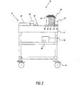
- Workstation 10 is configured to automatically aseptically collect, label, and store, in liquid collection device 12 (shown in FIG. 5 ), a plurality of liquid collections from a processing line or vessel (A).
- Workstation 10 is configured to automatically collect liquids such as, but not limited to, pharmaceutical products (e.g., medicines and vaccines), food products, biological products, biochemical products, chemical products and any combinations thereof.
- the collected liquid can be used as a sample, as an intermediate product, or as a finished product.
- workstation 10 is flexibly configured, namely is configured so that the workstation can be moved from point-to-point and/or from one process step to another process step in a manufacturing process. Further, workstation 10 is preferably suitable for use in an aseptic or clean room environment such that the material selection (e.g., stainless steel or other material) and material specifications (e.g., surface finish) are sufficient for use in such environments.
- material selection e.g., stainless steel or other material
- material specifications e.g., surface finish
- Workstation 10 includes a base or cabinet 14 supported, in some embodiments, by a plurality of wheels or casters 16 such that the workstation is mobile and can be positioned, as desired, in various locations within a processing facility.
- Workstation 10 is includes collection portion 18 for pumping liquid into collection device 12.
- Collection portion 18 includes a pump 20, a valve actuator 22, in some embodiments, a liquid edge detector 24, and a plurality of liquid holding areas 26.
- Pump 20 can be any desired pumping device but is, preferably, a non-contact pump that selectively draws liquid without directly contacting the liquid itself.
- pump 20 is a peristaltic pump.
- Liquid edge detector 24 can be any desired detector such as, but not limited to a sonic, a capacitance, or any other non-contacting or contacting sensor for determining the presence and absence of liquid in one or more areas of liquid collection device 12. Detector 24 can be in electrical communication with workstation 10 so that the workstation can detect when liquid is present in a predetermined location in liquid collection device 12.
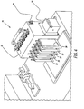
- liquid collection device 12 includes a plurality of product collection containers 28 (six shown), at least one waste container 30 (only one shown), and a valve block 32.
- Product containers 28 can be configured to have any desired volume so that the volumes of the product containers are identical to one another and/or different from one another.
- Product collection containers 28 and waste containers 30 can be any desired collection container such as, but not limited, collection bags as shown in FIG. 5 .
- containers 28, 30 can be collection bags such as the AllegroTM 2D Biocontainer, which is commercially available from Pall Corporation.
- each container 28, 30 includes an input line 29 releasably sealed with a clamp 33, an output line 31 releasably sealed with a clamp 33, and a port 35.
- containers 28, 30 be any sterile collection container including, but not limited to, collection bottles, collection boxes, collection syringes, and others.
- liquid collection device 12 includes five automated product collection containers 28 of identical volume, e.g., about 50 milliliters (mL), and one manual, collection container 28 of a larger volume, about 500 ml. Also, in the illustrated embodiment, the liquid collection device 12 includes one waste container 30 of about 1,000 mL. Of course, it should be recognized that the number and volumes of containers 28, 30 can be modified to any desired size.
- Device 12 further includes an input conduit 34 configured to place the processing line in liquid communication with valve block 32.
- Input conduit 34 includes at least one flexible portion 36.
- Portion 36 is configured to operably mate with pump 20 so that the pump can force the liquid into containers 28, 30 of liquid collection device 12.
- flexible portion 36 is made of a material having sufficient resiliency (e.g., silicone tubing) to operate in cooperation with the peristaltic pump.
- Liquid collection device 12 finds use with one or more two-part, aseptic connectors 38.
- input conduit 34 has only one part 38-1 of a two-part connector 38 connected thereto.
- the mating part 38-2 for two-part connector 38 of input conduit 36 is in liquid communication with processing line or vessel A.
- liquid collection device 12 can be liquidly connected to the processing line or vessel by joining both halves 38-1, 38-2 of two part-connector 38 at the input conduit and the processing line or vessel to one another.
- the portion of the two-part connector 38-2 mated with the production line or vessel A can be sterilized or sanitized along with the production line or vessel before processing of the liquid.
- Two-part connector 38 can be any disposable, two-part aseptic connector such as, but not limited to the KleenpakTM connector, which is commercially available from Pall Corporation, the Opta* SFT-I connector, which is commercially available from Sartorius Stedim Biotech, the Lynx® ST connector, which is commercially available from
- liquid collection device 12 product collection containers 28, waste collection container 30, and valve block 32 are removably connected to one another.
- liquid collection device 12 can include a plurality of connectors 39 such as, but not limited to Luer lock connectors.
- collection device 12 All product contact surfaces within collection device 12 are made of any material sufficient to hold or contact the liquid without interacting or contaminating the liquid. Moreover, collection device 12 can be packaged within one or more outer wrappings (not show) then can be sterilized using known sterilization methods such as, but not limited to, gamma irradiation. In this manner, collection device 12 can remain in a sterile condition until ready for use.
- Valve block 32 as shown in FIG. 6 , includes an input 40, a waste output 44, and a plurality of three-way valves 46 (six shown).
- the input 40 is in liquid communication with input conduit 34 and waste output 42 is in liquid communication with waste collection container 30.
- the plurality of three-way valves 44 correspond in number to the plurality of collection containers 28, with an output 46 from each of the valves being in liquid communication with a different collection container 28.
- Three-way valves 44 are each movable by rotation of a valve handle 48 among three positions: an "off” position; a "flush” position; and a “collection” position.
- each valve 44 prevents liquid from input 40 from flowing through the valve to either waste output 42 or output 46.
- each valve 44 allows liquid from input 40 to flow through the valve towards waste output 42, but prevents flow toward its respective output 46.
- each valve 44 allows liquid from input 40 to flow through the valve towards the respective output 46, but prevents flow toward the waste output 42.
- Handle 48 of each valve 44 operably mates with a different portion of valve actuator 22 so that the valve actuator can selectively rotate each handle independently of one another among the three positions.
- workstation 10 via valve actuator 22, is configured to actuate valve block 32 to selectively divert liquid from the processing line or vessel into any one of collection containers 28 or waste container 30.
- valves 44 are provided during various sampling activities contemplated by the present disclosure.
- valves 44 are sequentially numbered, in the direction of liquid flow, as valves 44-1 through 44-6 and the collection containers 28 are sequentially numbered, in the direction of liquid flow, as containers 28-1 through 28-6.
- TABLE NO. 1 VALVE POSITION Valve 44-1 Valve 44-2 Valve 44-3 Valve 44-4 Valve 44-5 Valve 44-6 Not in use Off Off Off Off Off Off Off Off Flush to waste container 30 Flush Flush Flush Flush Flush Flush Flush Divert to container 28-1 Divert Off Off Off Off Off Divert to container 28-2 Flush Divert Off Off Off Off Off Divert to container 28-3 Flush Flush Divert Off Off Off Off Divert to container 28-4 Flush Flush Flush Divert Off Off Divert to container 28-5 Flush Flush Flush Flush Divert Off Divert to container 28-6 Flush Flush Flush Flush Flush
- valves 44 are rotated to the "off" position, preventing liquid communication through valve block 32.
- each of the valves 44 Before collection and/or whenever it is desired to flush or prime the liquid flow path within liquid collection device 12, each of the valves 44 can be rotated to the "flush" position, placing input 40 in liquid communication with output 42. In this manner, liquid from input conduit 34 is diverted to waste container 30.
- the particular valve 44 associated with that particular container 28 is moved to the "collection" position. Further, any valve upstream, with respect to liquid flow through valve block 32, is moved to the flush position. Preferably, any valve 44 downstream, with respect to liquid flow through valve block 32, is moved to the off position. However, these downstream valves 44 can have any desired state.
- valves 44 are returned to the "off" position.
- liquid collection device 12 is positioned in workstation 10 so that flexible portion 36 of input conduit 34 is operatively positioned in pump 20 and so that valve block 32 is operatively positioned in valve actuator 22.
- the half of two-part connector 38 at input conduit 34 is operatively connected to its mating half arranged on the line or vessel.
- Valve actuator 22 can be used by the operator to manually operate valves 44.
- workstation 10 includes one or more valve operating buttons or controls 48.
- valve actuator 22 can be automatically controlled by workstation 12 as described in more detail herein below.
- valve actuator 22 it is contemplated by the present disclosure for valve actuator 22 to be controlled by any combination of manual and automated control.
- workstation 10 due to in part the use of two-part, aseptic connectors 38 in combination with liquid collection device 12, can be selectively moved from point-to-point within the manufacturing process to perform the desired sampling as needed. Also, workstation 10 can be installed in a particular location within the manufacturing line when that line is set up to make a first product, but can then be relocated to a different location within the manufacturing line when that line is set up to make a second product. In other words, workstation 10 can reduce the equipment cost to monitor a manufacturing process by being used in multiple locations within the manufacturing line during a production run or by being repositioned to a different stationary position when the manufacturing line is reconfigured to accommodate the manufacture of different products.
- Workstation 10 can, in some embodiments, include a product and waste container holding area 50, which can maintain containers 28, 30 in a desired position and/or in a desired conditions suitable for the liquid contained therein.
- workstation 10 can include environmental controls sufficient to maintain containers 28, 30, and thus, liquid contained therein, at a desired temperature.
- workstation 10 can include agitation and/or vibration devices sufficient to maintain the liquid within containers 28, 30 in a mixed or agitated state.
- Workstation 10 can include one or more sensors 52 to monitor and record the conditions (e.g., temperature, humidity) within base 14, the conditions within containers 28, 30 (e.g., temperature, turbidity, volume, etc), and other conditions of the workstation. Additionally, workstation 10 can include sensors or can connect to sensors outside 54 the workstation to monitor and records the conditions outside the base 12 including but not limited to temperature, pressure, humidity, particulates, and detection, typing and monitoring of viral and/or microbial organisms.
- conditions e.g., temperature, humidity
- containers 28, 30 e.g., temperature, turbidity, volume, etc
- workstation 10 to coordinate the control of pump 20, valve actuator 22, liquid edge detector 24 and sensors 50 within workstation 10 as well as collection of signals and data from any other (wireless or hardwire connected) human-machine input devices 56 such as, but not limited to, keyboards, and touch screens or any other data communication devices, USB or other data communication ports, CD or other data reading devices, computers, PLC's, analyzing equipments, testing devices and sensors outside the workstation.
- human-machine input devices 56 such as, but not limited to, keyboards, and touch screens or any other data communication devices, USB or other data communication ports, CD or other data reading devices, computers, PLC's, analyzing equipments, testing devices and sensors outside the workstation.
- liquid collection device 12 can include a disposable flow meter 58 in electrical communication with workstation 10.
- workstation 10 can include a processor 60 having human-machine-interface (HMI) 56 with one or more input devices 62 and one or more output devices 64.
- processor 60 can include devices such as, but not limited to, a computer, a programmable logic controller (PLC), or any other processor suitable to control the various components of workstation 10.
- HMI human-machine-interface
- PLC programmable logic controller
- HMI 56 can includes, for example, a keyboard, a mouse, a bar-code reader, a touch screen, a USB or other data communication port, CD or other data reading device, a remote control, or any other data communication device suitable for inputting commands to processor 60 in a wired and/or a wireless manner, and any combinations thereof.
- Output device 64 can include a computer monitor, an audible alarm device, a visual alarm device, a printer, a USB or other data communication port, a CD or other data writing device, a (wireless or hard-wired) data communication device or any other device suitable for receipt of a wired and/or a wireless output from processor 60.
- HMI 56 includes at least one bar code reader 62 and liquid collection device 12 can include at least one machine readable label 66, which includes details regarding the liquid collection device such as, but not limited to, the lot number, the expiration date, the number of product and waste containers 28, 30, the volume of product and waste containers 28, 30, the volume of conduits within the collection device, and other details.
- the operator can scan machine readable label 66 of liquid collection device 12 using bar code reader 62 so that processor 60 can determine and record the various details regarding the liquid collection device 12.
- output devices 64 include at least one printer.
- Processor 60 controls printer 64 to print labels, which can be applied by the operator directly on each container 28, 30 and includes information that is relevant to the liquid contained within the container.
- processor 60 can control printer 64 to print information such as, but not limited to, date of collection, time of collection, operator, batch ID, program sequence, room number, station number, collection location, and other process or environmental variables.
- printer 64 is configured to print information on the label in a machine readable language, such as a bar code, so that a laboratory technician can scan the machine readable code to input all relevant data related to the liquid within the container, which can mitigate instances of data entry errors.
- a machine readable language such as a bar code
- Processor 60 is in electrical communication via any wireless or wired manner such as, but not limited to, electrical, optical, audible, infrared, radiofrequency, magnetic and other means of communication with any one or more of pump 20, valve actuator 22, level sensor 24, manual controls 48, sensors 52 and 54, HMI 56, flow meter 58, output devices 60, as well as bar code reader 62 and printer 64.
- wireless or wired manner such as, but not limited to, electrical, optical, audible, infrared, radiofrequency, magnetic and other means of communication with any one or more of pump 20, valve actuator 22, level sensor 24, manual controls 48, sensors 52 and 54, HMI 56, flow meter 58, output devices 60, as well as bar code reader 62 and printer 64.
- processor 60 is configured to coordinate the control of workstation 10 and the collection of liquid in collection device 12, as well as to provide information on labels for placement onto containers 28, 30.
- processor 60 can communicate in wired and/or wireless manner with one or more computers (not shown) external to workstation 10, where such external computers can include data collection, data archiving, data analysis and data management software.
- the aseptic liquid collection ability of workstation 10 and collection device 12 mitigate or eliminate the risk of contaminating the collected liquid or the processing line.
- Workstation 10 via processor 60, can be programmed to aseptically obtain one or a series of liquid collections taken randomly, at manual selected times or at pre-set times and with manually selected volumes or pre-set volumes.
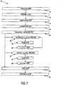
- FIG. 7 a method 70 of operating workstation 10 having liquid collection device 12 is shown.
- a first or selection step 72 the appropriate liquid collection device 12 for desired collection is selected by the operator.
- a second or assembly step 74 the operator assembles the selected liquid collection device 12 in workstation 10. Specifically, containers 28, 30 are placed in area 50, valve block 32 is operatively positioned in valve actuator 22, and flexible portion 36 of input conduit 34 is operatively positioned in pump 20. When level liquid edge detector 24 is present, a portion of input conduit 34 is operatively positioned in the detector.
- a third or verification step 76 the operator inputs information related to the liquid collection device 12 into processor 60 and inputs information related to the desired processing line or vessel from which workstation 10 will be collection the liquid.
- the verification step 76 includes requiring the operator to use scanner 62 to scan bar code 66 on liquid collection device 12.
- processor 60 verifies liquid collection device 12, the processor sends an output to the operator in a fourth or connection step 78 to instruct the operator to place the liquid collection device in liquid communication with the processing line or vessel via HMI 56.
- liquid collection device 12 is placed in liquid communication with the processing line or vessel by interconnecting two-part connector 38.
- Step 80 may initiate a manual collection process 82 using manual controls 48. Alternately, step 80 may initiate an automated collection process using an algorithm 84 resident on processor 60.
- algorithm 84 is configured to activate pump 20 to force liquid from the processing line or vessel through input conduit 34 and valve block 32 and into, as desired, any one of containers 28 and waste container 30.
- algorithm 84 is configured to control workstation 10 to a flush step 86.
- algorithm 84 flushes or purges liquid through liquid collection device 12 into waste container 30 for a predetermined period of time by moving all of the valves 44 to the "flush" position.
- algorithm 84 initiates a collection step 88 in which the processor 60 moves the plurality of valves 44 in the manner discussed above with respect to Table No, 1 to divert a desired volume of liquid into the desired collection container 28.
- algorithm 84 completes the collection step 88 by deactivating pump 20 and returning the valves 44 to the "off" position.
- Algorithm 84 repeats the flush and collection steps 86, 88 to activating pump 20 to flush liquid within liquid collection device 12 to waste container 30, divert the liquid to the desired product container 28, deactivates the pump, and closes the valves until all of the desired liquid collections have been obtained.
- algorithm 84 can use inputs from the flow meter to ensure proper liquid and purge volumes.
- algorithm 84 can use inputs from the sensor to ensure proper liquid and purge volumes.
- algorithm 84 is further configured to activate printer 64 to print data onto a label when a respective collection of liquid is obtained during a print step 90. The operator can then apply the label on the appropriate container 28, respectively.
- algorithm 84 can be configured to activate printer 64 to print waste related data onto a label when the respective waste is collected or after all of the waste has been collected.
- the operator can manually and/or via controller 60 flush liquid collection device 12 to waste container 30 during a manual flush step 96 and divert a desired volume of liquid to the manual container 28, when present, during a manual collection step 98.
- the operator can, during a disconnection step 92, disconnect liquid collection device 12 from the processing line or vessel by separating two-part connector 38. Similarly, the operator can remove each product container 28 and waste container 30 from liquid collection device 12 by separating two-part connectors 38.
- algorithm 84 purges a predetermined amount liquid from with liquid collection device 12 before taking each collection of liquid to ensure that the liquid collected in product container 28 is representative of liquid in the processing line or vessel at the time of the collection.
- waste container 30 has a volume that is sufficient to hold the purged liquid.
- a ratio of the volume of the waste container 30 to the volume of the product container 28 is not more than 15:1, more preferably 10:1, with between 5:1 to 2:1 being most preferred.
- waste container 30 provides a volume sufficient to allow liquid collection device 12 to be flushed before taking each of the collections to ensure that the liquid collected in the product container 28 is representative of the liquid in the processing line and, not, liquid remaining within the liquid collection device from the prior diverted liquid.
- verification step 76 from method 70 is shown in more detail.
- processor 60 requires the user to scan bar code 66 on liquid collection device 12 using scanner 62 in a scanning step 100.
- method 70 can further include a process identification step 102, where parameters and/or details of the process and/or liquid to be collected are entered into processor 60.
- the parameters and/or details can be entered manually into processor 60 by the operator, can be scanned into processor 60 using scanner 62 and an identifier located on the batch record and/or the process equipment, or any combination of manual and scanning data entry.
- Verification step 76 determines, based on data within processor 60 and information from bar code 66, whether liquid collection device 12 is new or has been previously used at a step 104. If the liquid collection device 12 has been previously used, verification step 76 returns the user to assembly step 74 so that a new collection device can be used.
- verification step 76 compares the details of the liquid collection device (e.g., size and number of containers 28, 30) to the collection protocol stored within processor 60 for the process being monitored at step 106. If the liquid collection device 12 is not correct for the desired collection profile, verification step 76 returns the user to assembly step 74 so that a correct collection device can be used.
- the details of the liquid collection device e.g., size and number of containers 28, 30
- verification step 76 logs liquid collection device 12 as being previously used within processor 60 at step 108 and instructs the operator at connection step 78 to place the liquid collection device in liquid communication with the processing line or vessel via HMI 56. As discussed in detail above, liquid collection device 12 is placed in liquid communication with the processing line or vessel by interconnecting two-part connector 38.
- containers 28, 30 are described as being bags. However, it is contemplated by the present disclosure for containers 28, 30 to be any desired sterile container. Referring now to FIGS. 9a through 9c , alternate exemplary embodiments of containers 28, 30 are shown and are indicated using multiples of one hundred.
- container 228, 230 is illustrated as a fluid holding transport box.
- Container 228, 230 can be permanently or removably connected to liquid collection device 12.
- container 228, 230 includes a connector 239 such as, but not limited to Luer lock connector, for connection to liquid collection device 12.
- container 228, 230 is sufficiently rigid such that the container further includes a sterile vent 240.
- Vent 240 allows gas within container 228, 230 to exit the container as the liquid is diverted into the container.
- vent 240 preferably prevents gas outside of container 228, 230 from entering the container and prevents liquid inside the container from exiting the container.
- Vent 240 can be any sterile vent such as, but not limited to, the PHARMAVENT vent and the Fine Spike Vent, both of which are commercially available from CliniMed Holdings Limited.
- collapsible bags prefferably include a sterile vent thereon as needed.
- container 328, 330 is illustrated as a fluid holding bottle. Again, container 328, 330 can be permanently or removably connected to liquid collection device 12 and therefore can optionally include a connector 339 for connection to the liquid collection device. Additionally, container 328, 330 is sufficiently rigid such that the container further includes a sterile vent 340 as discussed above.
- container 428, 430 is illustrated as a fluid holding syringe. Again, container 428, 430 can be permanently or removably connected to liquid collection device 12 and therefore can optionally include a connector 439 for connection to the liquid collection device.
- Container 428, 430 includes a chamber 442 with a piston 444 slideably received therein. Before use, piston 444 is pressed into chamber 442 so that a volume of gas within container 428, 430 is minimized. As workstation 10 diverts liquid into container 428, 430, piston 440 is pushed or slid within chamber 442 such that the fluid holding syringe does not require a separate vent.
- the liquid collection containers for both product and waste can be any flexible or rigid container, bottle or carpule that allows for the diversion of liquid into the container, while allowing gas within the container to either vent or allowing the container itself to expand or move to accommodate the input liquid.
Landscapes
- Life Sciences & Earth Sciences (AREA)
- Health & Medical Sciences (AREA)
- Chemical & Material Sciences (AREA)
- General Health & Medical Sciences (AREA)
- Biochemistry (AREA)
- Zoology (AREA)
- Engineering & Computer Science (AREA)
- Bioinformatics & Cheminformatics (AREA)
- Organic Chemistry (AREA)
- Wood Science & Technology (AREA)
- Physics & Mathematics (AREA)
- General Physics & Mathematics (AREA)
- Pathology (AREA)
- Immunology (AREA)
- Analytical Chemistry (AREA)
- Hydrology & Water Resources (AREA)
- Biomedical Technology (AREA)
- Genetics & Genomics (AREA)
- Molecular Biology (AREA)
- Biotechnology (AREA)
- Sustainable Development (AREA)
- General Engineering & Computer Science (AREA)
- Microbiology (AREA)
- Sampling And Sample Adjustment (AREA)
- Apparatus Associated With Microorganisms And Enzymes (AREA)
Applications Claiming Priority (2)
| Application Number | Priority Date | Filing Date | Title |
|---|---|---|---|
| US12/959,647 US8640556B2 (en) | 2010-12-03 | 2010-12-03 | Automated aseptic sampling workstation and sample collection devices therefore |
| US13/118,891 US8815179B2 (en) | 2010-12-03 | 2011-05-31 | Automated aseptic liquid collection workstations and collection devices therefore |
Publications (1)
| Publication Number | Publication Date |
|---|---|
| EP2487478A1 true EP2487478A1 (de) | 2012-08-15 |
Family
ID=45350586
Family Applications (1)
| Application Number | Title | Priority Date | Filing Date |
|---|---|---|---|
| EP20110009544 Withdrawn EP2487478A1 (de) | 2010-12-03 | 2011-12-02 | Automatische aseptische Flüssigkeitssammel-Arbeitsstationen und Sammelvorrichtungen dafür |
Country Status (9)
| Country | Link |
|---|---|
| US (2) | US8815179B2 (de) |
| EP (1) | EP2487478A1 (de) |
| JP (2) | JP5596006B2 (de) |
| CN (1) | CN102564809A (de) |
| AU (1) | AU2011253808B2 (de) |
| BR (1) | BRPI1105212A2 (de) |
| CA (1) | CA2761888A1 (de) |
| MX (1) | MX2011012902A (de) |
| TW (1) | TWI495813B (de) |
Cited By (2)
| Publication number | Priority date | Publication date | Assignee | Title |
|---|---|---|---|---|
| EP3617690A1 (de) * | 2018-08-31 | 2020-03-04 | Endress + Hauser Conducta GmbH + Co. KG | Probenahmebehältnis, probenahmesystem und probenahmeverfahren zur verarbeitung einer flüssigen probe |
| CN111060358A (zh) * | 2020-01-15 | 2020-04-24 | 王群峰 | 一种自动逐级取样的污水处理取样装置 |
Families Citing this family (24)
| Publication number | Priority date | Publication date | Assignee | Title |
|---|---|---|---|---|
| US8815179B2 (en) * | 2010-12-03 | 2014-08-26 | Alfa Wassermann, Inc. | Automated aseptic liquid collection workstations and collection devices therefore |
| EP2885528A4 (de) * | 2012-07-09 | 2016-12-07 | Alfa Wassermann Inc | Flüssigkeitsaufnahmeverfahren und -vorrichtungen zur erkennung einer virusdeaktivierung |
| US10190950B2 (en) | 2014-10-31 | 2019-01-29 | General Electric Company | Semi-automated sampling system for aseptic sampling |
| US9677975B2 (en) | 2014-10-31 | 2017-06-13 | General Electric Company | Systems and methods for aseptic sampling |
| CN105110281B (zh) * | 2015-08-11 | 2017-11-28 | 欧先金 | 一种液体自动摄取并恒温储存的装置和方法 |
| CN105647789B (zh) * | 2016-01-29 | 2019-01-04 | 清华大学 | 一种基于微流控芯片的细胞代谢产物实时检测装置 |
| CN105605281B (zh) * | 2016-03-23 | 2018-05-15 | 氟络塞尔特种阀门(苏州)有限公司 | 一种电动阀门自动监控分析流体的方法 |
| CN105605282A (zh) * | 2016-03-23 | 2016-05-25 | 氟络塞尔特种阀门(苏州)有限公司 | 一种监控分析流体的自动电动阀门 |
| US10668484B2 (en) | 2016-07-22 | 2020-06-02 | Alfa Wassermann, Inc. | Fluid handling systems and method for ultracentrifuges |
| WO2019126801A1 (en) | 2017-12-21 | 2019-06-27 | Sentinel Monitoring Systems, Inc. | Aseptic sampling system |
| CA3175039A1 (en) | 2020-03-10 | 2021-09-16 | Cellares Corporation | Systems, devices, and methods for cell processing |
| CN112729950A (zh) * | 2020-12-26 | 2021-04-30 | 中国科学院地球化学研究所 | 一种自动定期分层收集土壤水的系统 |
| CN113213406B (zh) * | 2021-04-30 | 2021-10-19 | 龙港诚宝实业有限公司 | 一种香木罐的生产工艺 |
| CN113188843B (zh) * | 2021-05-10 | 2022-09-02 | 江西怡杉环保股份有限公司 | 一种水质采样设备 |
| JP2023066521A (ja) * | 2021-10-29 | 2023-05-16 | サクラ精機株式会社 | カバースリップ貼着装置 |
| CN120897988A (zh) | 2023-03-21 | 2025-11-04 | 赛阿瑞斯公司 | 用于在细胞处理系统内的电穿孔的系统、设备和方法 |
| US12399193B2 (en) | 2023-05-05 | 2025-08-26 | Cellares Corporation | Systems, devices, and methods for combined cell processes |
| CN121752711A (zh) | 2023-06-30 | 2026-03-27 | 赛阿瑞斯公司 | 用于自动化细胞处理系统内的流体转移的系统、装置和方法 |
| US12305156B2 (en) | 2023-08-21 | 2025-05-20 | Cellares Corporation | Systems, devices, and methods for fluid control in a cell processing system |
| WO2025041064A2 (en) | 2023-08-21 | 2025-02-27 | Cellares Corporation | Systems, devices, and methods for automatic cell sorting |
| US12497587B2 (en) | 2023-08-21 | 2025-12-16 | Cellares Corporation | Bioreactors and methods of their use in automatic cell processing systems |
| US12492368B2 (en) | 2024-03-11 | 2025-12-09 | Cellares Corporation | Monitoring air pressure within a cell processing system |
| US12559710B2 (en) | 2024-03-27 | 2026-02-24 | Cellares Corporation | Liquid level and flow rate detection within a cell processing system |
| USD1109621S1 (en) | 2024-04-15 | 2026-01-20 | Cellares Corporation | Analytical platform for biological material testing |
Citations (7)
| Publication number | Priority date | Publication date | Assignee | Title |
|---|---|---|---|---|
| US3848581A (en) * | 1971-10-08 | 1974-11-19 | L Cinqualbre | Apparatus for taking multiple samples of biological liquid |
| FR2358601A1 (fr) * | 1976-09-29 | 1978-02-10 | Paley Hyman | Distributeur |
| EP0086098A1 (de) * | 1982-02-08 | 1983-08-17 | Merck & Co. Inc. | Vielfache Flüssigkeitsabfüllvorrichtung |
| US4454772A (en) * | 1981-11-06 | 1984-06-19 | Texaco Inc. | Method for sampling a fluid from a well |
| WO1990009431A1 (en) * | 1989-02-13 | 1990-08-23 | Baxter International Inc. | Apparatus and method for periodic aseptic withdrawal of liquid samples from a sterile liquid source |
| EP0637712A1 (de) * | 1993-08-06 | 1995-02-08 | Vygon | Ventilverteiler |
| WO2007125023A1 (en) * | 2006-04-28 | 2007-11-08 | Technische Universität Berlin | Apparatus for obtaining samples of a fluid and method for cleaning such apparatus |
Family Cites Families (40)
| Publication number | Priority date | Publication date | Assignee | Title |
|---|---|---|---|---|
| CA819408A (en) | 1969-08-05 | Texsteam Corporation | Pipeline sampler | |
| CA1065720A (en) * | 1976-07-05 | 1979-11-06 | Hyman W. Paley | Plastic manifold assembly |
| US4307620A (en) | 1978-03-04 | 1981-12-29 | Jiskoot Joost J | Liquid sampling system |
| US4691850A (en) * | 1984-08-09 | 1987-09-08 | Kirschmann John D | Chemical dispensing system |
| JPH03123268U (de) * | 1990-03-28 | 1991-12-16 | ||
| JPH05170288A (ja) * | 1991-12-20 | 1993-07-09 | Tokico Ltd | 採取装置 |
| WO1996012952A1 (en) | 1994-10-20 | 1996-05-02 | Eai Corporation | Air transportable, modular analytical laboratory |
| SE507448C2 (sv) | 1995-11-02 | 1998-06-08 | Novaseptum Ab | Anordning för införande och/eller uttagande av medium i en behållare innefattande en kanyl och ett membran |
| US6902703B2 (en) | 1999-05-03 | 2005-06-07 | Ljl Biosystems, Inc. | Integrated sample-processing system |
| US6216918B1 (en) | 1999-11-10 | 2001-04-17 | Shurflo Pump Manufacturing Company, Inc. | Apparatus and method for sterilizing a fluid dispensing device |
| US7351376B1 (en) * | 2000-06-05 | 2008-04-01 | California Institute Of Technology | Integrated active flux microfluidic devices and methods |
| DE60209131T2 (de) | 2001-10-09 | 2006-09-28 | Millipore Corp., Billerica | Automatisiertes system zur filtration von flüssigkeiten sowie zur erfassung und aufzeichnung von messdaten |
| JP2003123268A (ja) | 2001-10-18 | 2003-04-25 | Sanyo Electric Co Ltd | 記録媒体、情報記録装置、情報再生装置および情報レンタルシステム |
| US7381375B2 (en) | 2001-10-26 | 2008-06-03 | Millipore Corporation | Assay systems with adjustable fluid communication |
| JP2004018112A (ja) | 2002-06-19 | 2004-01-22 | Yasuzumi Tanaka | 複数の密封弁なし単独袋を有する梱包シート |
| US7824623B2 (en) | 2003-06-24 | 2010-11-02 | Millipore Corporation | Multifunctional vacuum manifold |
| WO2005009324A2 (en) * | 2003-07-22 | 2005-02-03 | Scriptpro Llc | Fork based transport storage system |
| EP1508791A1 (de) | 2003-08-22 | 2005-02-23 | Ismatec SA, Laboratoriumstechnik | Vorrichtung zur automatischen Probenentnahme aus einem Bioreaktor |
| US7377686B2 (en) | 2003-09-04 | 2008-05-27 | Millipore Corporation | Disposable mixing system |
| JP2005170288A (ja) | 2003-12-12 | 2005-06-30 | Ichikoh Ind Ltd | 車両用映像表示装置 |
| US7293477B2 (en) | 2003-12-23 | 2007-11-13 | Millipore Corporation | Disposable, pre-sterilized fluid receptacle sampling device |
| US7578205B2 (en) | 2005-06-01 | 2009-08-25 | Millipore Corporation | Sterile sampling device |
| US7810674B2 (en) * | 2005-07-26 | 2010-10-12 | Millipore Corporation | Liquid dispensing system with enhanced mixing |
| JP2007067968A (ja) | 2005-08-31 | 2007-03-15 | Cna Inc | 鍵管理システム、鍵管理サーバ及び鍵管理方法 |
| US7467890B2 (en) | 2005-11-04 | 2008-12-23 | Custom Ultrasonics, Inc. | Portable chemical transfer/neutralizing containment system |
| US7560071B2 (en) | 2006-03-29 | 2009-07-14 | Nichols Michael J | Instrument docking station for an automated testing system |
| GB2445745B (en) | 2007-01-17 | 2009-12-09 | Schlumberger Holdings | System and method for analysis of well fluid samples |
| CN101765448A (zh) | 2007-08-02 | 2010-06-30 | 米利波尔公司 | 用于处理流体样品的系统和装置 |
| US8323246B2 (en) * | 2008-01-02 | 2012-12-04 | The Regents Of The University Of Michigan | Dual drug delivery device |
| FR2940440B1 (fr) | 2008-12-18 | 2010-12-24 | Millipore Corp | Dispositif pour le transfert d'un milieu |
| FR2941603B1 (fr) | 2009-02-04 | 2015-07-17 | Millipore Corp | Dispositif pour supporter une pluralite de recipients souples pour liquide. |
| CN201464219U (zh) * | 2009-05-18 | 2010-05-12 | 洛阳毅兴石化电器仪表设备有限公司 | 全单向在线气、液密闭采样器 |
| US20100300563A1 (en) * | 2009-05-27 | 2010-12-02 | John Ramunas | Modular device and method for moving fluids to and from a sample delivery element |
| US20110201100A1 (en) | 2010-01-19 | 2011-08-18 | Millipore Corporation | Single use cell culture bioreactor manifold system |
| CN101825559B (zh) * | 2010-05-04 | 2012-01-04 | 中国科学院南海海洋研究所 | 一种自动进样装置 |
| CN102971565B (zh) | 2010-07-01 | 2016-06-01 | Emd密理博公司 | 刚性一次性流路 |
| ES2774949T3 (es) | 2010-08-10 | 2020-07-23 | Emd Millipore Corp | Método para la eliminación de retrovirus |
| US8815179B2 (en) * | 2010-12-03 | 2014-08-26 | Alfa Wassermann, Inc. | Automated aseptic liquid collection workstations and collection devices therefore |
| WO2012150991A2 (en) | 2011-03-03 | 2012-11-08 | Emd Millipore Corporation | Tubing and connector and method making the same |
| CN107064491B (zh) | 2011-05-11 | 2019-05-28 | Emd密理博公司 | 免疫测定产品和过程 |
-
2011
- 2011-05-31 US US13/118,891 patent/US8815179B2/en not_active Expired - Fee Related
- 2011-12-02 TW TW100144318A patent/TWI495813B/zh not_active IP Right Cessation
- 2011-12-02 MX MX2011012902A patent/MX2011012902A/es active IP Right Grant
- 2011-12-02 EP EP20110009544 patent/EP2487478A1/de not_active Withdrawn
- 2011-12-02 AU AU2011253808A patent/AU2011253808B2/en not_active Ceased
- 2011-12-05 JP JP2011265576A patent/JP5596006B2/ja not_active Expired - Fee Related
- 2011-12-05 BR BRPI1105212-0A patent/BRPI1105212A2/pt not_active IP Right Cessation
- 2011-12-05 CN CN2011103990993A patent/CN102564809A/zh active Pending
- 2011-12-05 CA CA 2761888 patent/CA2761888A1/en not_active Abandoned
-
2012
- 2012-07-09 US US13/543,951 patent/US9664597B2/en not_active Expired - Fee Related
-
2014
- 2014-08-06 JP JP2014160721A patent/JP2015015951A/ja active Pending
Patent Citations (7)
| Publication number | Priority date | Publication date | Assignee | Title |
|---|---|---|---|---|
| US3848581A (en) * | 1971-10-08 | 1974-11-19 | L Cinqualbre | Apparatus for taking multiple samples of biological liquid |
| FR2358601A1 (fr) * | 1976-09-29 | 1978-02-10 | Paley Hyman | Distributeur |
| US4454772A (en) * | 1981-11-06 | 1984-06-19 | Texaco Inc. | Method for sampling a fluid from a well |
| EP0086098A1 (de) * | 1982-02-08 | 1983-08-17 | Merck & Co. Inc. | Vielfache Flüssigkeitsabfüllvorrichtung |
| WO1990009431A1 (en) * | 1989-02-13 | 1990-08-23 | Baxter International Inc. | Apparatus and method for periodic aseptic withdrawal of liquid samples from a sterile liquid source |
| EP0637712A1 (de) * | 1993-08-06 | 1995-02-08 | Vygon | Ventilverteiler |
| WO2007125023A1 (en) * | 2006-04-28 | 2007-11-08 | Technische Universität Berlin | Apparatus for obtaining samples of a fluid and method for cleaning such apparatus |
Cited By (3)
| Publication number | Priority date | Publication date | Assignee | Title |
|---|---|---|---|---|
| EP3617690A1 (de) * | 2018-08-31 | 2020-03-04 | Endress + Hauser Conducta GmbH + Co. KG | Probenahmebehältnis, probenahmesystem und probenahmeverfahren zur verarbeitung einer flüssigen probe |
| US11926457B2 (en) | 2018-08-31 | 2024-03-12 | Endress+Hauser Conducta Gmbh+Co. Kg | Sampling container, sampling system and sampling method for processing a liquid sample |
| CN111060358A (zh) * | 2020-01-15 | 2020-04-24 | 王群峰 | 一种自动逐级取样的污水处理取样装置 |
Also Published As
| Publication number | Publication date |
|---|---|
| JP2015015951A (ja) | 2015-01-29 |
| JP5596006B2 (ja) | 2014-09-24 |
| MX2011012902A (es) | 2012-08-31 |
| US20140007711A1 (en) | 2014-01-09 |
| US8815179B2 (en) | 2014-08-26 |
| US9664597B2 (en) | 2017-05-30 |
| AU2011253808A1 (en) | 2012-06-21 |
| BRPI1105212A2 (pt) | 2015-07-28 |
| CN102564809A (zh) | 2012-07-11 |
| CA2761888A1 (en) | 2012-06-03 |
| US20120138156A1 (en) | 2012-06-07 |
| JP2012135303A (ja) | 2012-07-19 |
| TW201233924A (en) | 2012-08-16 |
| AU2011253808B2 (en) | 2014-12-18 |
| TWI495813B (zh) | 2015-08-11 |
Similar Documents
| Publication | Publication Date | Title |
|---|---|---|
| US8815179B2 (en) | Automated aseptic liquid collection workstations and collection devices therefore | |
| US20140060214A1 (en) | Automated Aseptic Sampling Workstations and Sample Collection Devices Therefore | |
| US10809275B2 (en) | Verification pipette and vision apparatus | |
| US8191339B2 (en) | Automated drug preparation apparatus including automated drug reconstitution | |
| JP7408211B2 (ja) | バイオ医薬製品のための監視システムおよび方法 | |
| US20100241270A1 (en) | Automated Pharmacy Admixture System | |
| CN106660005B (zh) | 用于处理生物处理流体的系统和方法 | |
| AU2020434019A1 (en) | Autosamplers and analytic systems and methods including same | |
| AU2017299804B2 (en) | Fluid handling systems and method for ultracentrifuges | |
| US20210390320A1 (en) | Method and System for Monitoring a Set-Up for Manufacture of a Biopharmaceutical Product | |
| US20100116876A1 (en) | Laboratory sampling machine and methods for maintaining chain of custody for samples | |
| EP2885528A1 (de) | Flüssigkeitsaufnahmeverfahren und -vorrichtungen zur erkennung einer virusdeaktivierung | |
| KR20120061763A (ko) | 자동 살균 액체 회수 워크스테이션 및 그 회수 장치 | |
| JP7803515B2 (ja) | 医薬品のためのシステムおよび方法 | |
| EP4501301B1 (de) | Vorrichtung und verfahren zur herstellung von arzneimitteln |
Legal Events
| Date | Code | Title | Description |
|---|---|---|---|
| PUAI | Public reference made under article 153(3) epc to a published international application that has entered the european phase |
Free format text: ORIGINAL CODE: 0009012 |
|
| AK | Designated contracting states |
Kind code of ref document: A1 Designated state(s): AL AT BE BG CH CY CZ DE DK EE ES FI FR GB GR HR HU IE IS IT LI LT LU LV MC MK MT NL NO PL PT RO RS SE SI SK SM TR |
|
| AX | Request for extension of the european patent |
Extension state: BA ME |
|
| 17P | Request for examination filed |
Effective date: 20130215 |
|
| STAA | Information on the status of an ep patent application or granted ep patent |
Free format text: STATUS: THE APPLICATION HAS BEEN WITHDRAWN |
|
| 18W | Application withdrawn |
Effective date: 20161013 |