EP2487645A1 - Verfahren zur Steuerung der Feldtiefe für eine kleine Sensorkamera mithilfe einer EDOF-Erweiterung - Google Patents
Verfahren zur Steuerung der Feldtiefe für eine kleine Sensorkamera mithilfe einer EDOF-Erweiterung Download PDFInfo
- Publication number
- EP2487645A1 EP2487645A1 EP11153900A EP11153900A EP2487645A1 EP 2487645 A1 EP2487645 A1 EP 2487645A1 EP 11153900 A EP11153900 A EP 11153900A EP 11153900 A EP11153900 A EP 11153900A EP 2487645 A1 EP2487645 A1 EP 2487645A1
- Authority
- EP
- European Patent Office
- Prior art keywords
- depth
- focal plane
- field
- image
- lens
- Prior art date
- Legal status (The legal status is an assumption and is not a legal conclusion. Google has not performed a legal analysis and makes no representation as to the accuracy of the status listed.)
- Withdrawn
Links
Images



Classifications
-
- G—PHYSICS
- G06—COMPUTING OR CALCULATING; COUNTING
- G06T—IMAGE DATA PROCESSING OR GENERATION, IN GENERAL
- G06T5/00—Image enhancement or restoration
- G06T5/50—Image enhancement or restoration using two or more images, e.g. averaging or subtraction
-
- H—ELECTRICITY
- H04—ELECTRIC COMMUNICATION TECHNIQUE
- H04N—PICTORIAL COMMUNICATION, e.g. TELEVISION
- H04N23/00—Cameras or camera modules comprising electronic image sensors; Control thereof
- H04N23/60—Control of cameras or camera modules
- H04N23/67—Focus control based on electronic image sensor signals
- H04N23/675—Focus control based on electronic image sensor signals comprising setting of focusing regions
-
- H—ELECTRICITY
- H04—ELECTRIC COMMUNICATION TECHNIQUE
- H04N—PICTORIAL COMMUNICATION, e.g. TELEVISION
- H04N23/00—Cameras or camera modules comprising electronic image sensors; Control thereof
- H04N23/80—Camera processing pipelines; Components thereof
- H04N23/815—Camera processing pipelines; Components thereof for controlling the resolution by using a single image
-
- H—ELECTRICITY
- H04—ELECTRIC COMMUNICATION TECHNIQUE
- H04N—PICTORIAL COMMUNICATION, e.g. TELEVISION
- H04N23/00—Cameras or camera modules comprising electronic image sensors; Control thereof
- H04N23/80—Camera processing pipelines; Components thereof
- H04N23/84—Camera processing pipelines; Components thereof for processing colour signals
-
- H—ELECTRICITY
- H04—ELECTRIC COMMUNICATION TECHNIQUE
- H04N—PICTORIAL COMMUNICATION, e.g. TELEVISION
- H04N5/00—Details of television systems
- H04N5/222—Studio circuitry; Studio devices; Studio equipment
- H04N5/262—Studio circuits, e.g. for mixing, switching-over, change of character of image, other special effects ; Cameras specially adapted for the electronic generation of special effects
- H04N5/2621—Cameras specially adapted for the electronic generation of special effects during image pickup, e.g. digital cameras, camcorders, video cameras having integrated special effects capability
Definitions
- a photograph can sometimes have an appealing effect if the subject of the photograph is in focus while objects in the far background and near foreground are somewhat out of focus.
- the distance from a camera at which a subject is in sharpest focus can be referred to as the focal plane.
- the total distance in front and behind the focal plane in which objects are perceived to be in focus can be referred to as the depth of field.
- the subject is ten feet away from a camera with an adjustable lens
- the photographer can adjust the focus on the lens so that objects ten feet away are in sharp focus.
- the focal plane would then be ten feet away.
- the photographer might also be able to adjust the lens and other properties of the camera such that objects just in front of and just behind the subject are also somewhat in focus. For example, objects up to one foot in front of the subject and up to two feet behind the subject might be kept in focus.
- the depth of field would then be three feet.
- a large aperture number corresponds to a small lens opening
- a small aperture number corresponds to a large lens opening.
- a small lens opening a large number of objects throughout the field can be in focus. That is, when the lens opening is small, all objects from a point relatively near the camera to a point relatively far from the camera might be in focus. Therefore, when the aperture number is large, and the lens opening is correspondingly small, a large depth of field is obtained. Conversely, a small aperture number and large lens opening can create a narrow depth of field.
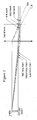
- Figure 1 illustrates a focal plane for blue light.
- Figure 2 illustrates a focal plane for green light.
- Figure 3 illustrates a focal plane for red light.
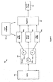
- Figure 4 illustrates a system that allows adjustment of a focal plane and depth of field for a photographic image captured by a fixed-lens camera, according to an implementation of the disclosure.
- Figure 5 is a flowchart for a method for providing an adjustable focal plane for a photograph after data related to the photograph has been captured, according to an implementation of the disclosure.
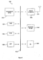
- Figure 6 illustrates a processor and related components suitable for implementing the present disclosure.
- Implementations of the present disclosure allow a focal plane and depth of field to be selected for a photograph taken on a camera that does not have an adjustable aperture.
- a photographer can specify a focal plane and depth of field after the camera has captured an image.
- An algorithm can then manipulate the raw data associated with the image to produce a photograph with the desired focal plane and depth of field.
- Small “point and shoot” type digital cameras typically include a fixed lens that does not allow the user to adjust the lens aperture. Therefore, the user cannot control the focal plane or depth of field of a photograph taken with such a camera.
- the digital cameras that might be included in multi-function devices such as telephones, smart phones, personal digital assistants, handheld or laptop computers, and similar devices also typically lack this capability. All such cameras and all such devices that include such cameras will be referred to herein as fixed-lens cameras.
- the lenses on fixed-lens cameras are typically quite small and have a correspondingly small lens opening.
- the depth of field for photographs taken with fixed-lens cameras can therefore be quite large.
- all objects in the range from two feet from the camera to infinity might be in focus. Since the size of the lens opening on such cameras typically cannot be adjusted, this depth of field cannot be changed. Therefore, a photograph of an object that is closer to a fixed-lens camera than about two feet might be out of focus.
- EDOF extended depth of field
- Each wavelength of light passing through such a lens might produce an image that is in focus at a distance from the lens that is different from the distance at which an image in a different wavelength might be in focus.
- blue light might correspond to a focal plane one foot away from the lens, as shown in Figure 1
- green light might correspond to a focal plane five feet away from the lens, as shown in Figure 2
- red light might correspond to a focal plane far away from the camera, as shown in Figure 3 . Therefore, a pure blue object will be in focus at one foot away from the lens, a pure green object will be in focus at five feet away from the lens, and a red object will be in focus when far away from the camera.
- the focal planes given here for different wavelengths of light are merely examples and that objects with these colors might be in focus at other distances.
- An EDOF camera features a lens designed to control the longitudinal chromatic aberrations in a way that ensures at least one color channel of the image sensor contains in-focus information. For example, for a typical red/green/blue (RGB) sensor, a red image, a green image, and a blue image of a single object might be captured, and at least one will be in focus.
- RGB red/green/blue
- a known algorithm is then used for each region of the image to identify the sharpest color channel. Then, for each region of the image, the algorithm transports the sharpness from the sharpest color to the other color channels. Finally, the sharpness-improved color channels are combined to form a final digital image with a depth of field greater than would otherwise be possible.
- Implementations of the present disclosure for a Controllable Depth of Field can produce effects that extend beyond those of EDOF.
- CDOF allows the depth of field for a fixed-lens camera to be increased or decreased. Increasing the depth of field is already covered by the EDOF technology. However, decreasing the depth of field, as provided with CDOF, has an effect of separating the picture subject from the background and foreground of the picture, a technique often used in portrait pictures to focus the viewer's attention on the picture subject.
- the disclosure also provides a method of controlling the perceived location of the focal plane in the generated digital picture. A focusing capability is thereby provided to fixed-lens cameras that otherwise would not have an adjustable focus.
- the CDOF capability is achieved through the use of a lens with a controlled longitudinal chromatic aberration.
- a plurality of color channel data buffers captured through such a lens are saved and then made available to a user-controlled process for selection of a focal plane and depth of field.
- Algorithms similar to those used in EDOF can then be applied to the saved images to generate a photograph that has the desired focal plane and depth of field.
- Figure 4 illustrates an implementation of a system 100 for specifying a focal plane and depth of field for a photograph after a photographic image has been captured.
- the system 100 might be implemented in a fixed-lens camera or in other types of cameras.
- Light from a desired photographic subject is allowed to enter a lens 110 that has a controlled longitudinal chromatic aberration.
- the lens 110 separates the incident light into a plurality of components with different wavelengths.
- the light emerging from the lens 110 enters a sensor 120 that includes a plurality of pixel elements 130. Each of the pixels 130 is configured to detect one of the constituent wavelengths of the incident light.
- each pixel 130 there are three pixels 130, a red pixel 130a configured to detect light near the red portion of the spectrum, a green pixel 130b configured to detect light near the green portion of the spectrum, and a blue pixel 130c configured to detect light near the blue portion of the spectrum.
- red pixel 130a configured to detect light near the red portion of the spectrum
- green pixel 130b configured to detect light near the green portion of the spectrum
- blue pixel 130c configured to detect light near the blue portion of the spectrum.
- other numbers of pixels 130 could be present and other portions of the visible spectrum could be detected.
- Each pixel color has a corresponding color channel buffer 140 associated with it.
- Each of the pixels 130 sends to a corresponding color channel buffer 140 an image comprised of the constituent wavelength of light that that pixel 130 has been configured to detect. That is, the red pixel 130a sends an image that contains the red components of the incident light to a red channel buffer 140a, the green pixel 130b sends an image that contains the green components of the incident light to a green buffer channel 140b, and the blue pixel 130c sends an image that contains the blue components of the incident light to a blue channel buffer 140c. If a different number or type of pixels 130 were present in the sensor 120, a corresponding number or type of color channel buffers 140 would be present. Each color channel buffer 140 stores the image that it receives from the corresponding pixel 130. The images stored in the color channel buffers 140 can be referred to as raw images.
- each raw image stored in one of the color channel buffers 140 has an individual depth of field contained within the extended depth of field range of the EDOF system.
- the raw image stored in the blue channel buffer 140c might have a depth of field surrounding a focal plane one foot away from the lens 110; this can be seen as the macro range.
- the raw image stored in the green channel buffer 140b might have a depth of field surrounding a focal plane five feet away from the lens 110; this can be seen as the portrait range.
- the raw image stored in the red channel buffer 140a might have a depth of field covering the far end; this can be seen as the landscape range. In other implementations, the raw images might have different depth of field ranges.
- the raw images in the color channel buffers 140 are made available to an algorithm 150 that can generate a final digital image 170.
- the algorithm 150 for the Controlled Depth of Field, CDOF considers that a lens with the properly designed longitudinal chromatic aberration is used such that at least one color channel of the image sensor contains in-focus information. A consequence of this is that, due to the lack of simultaneous in-focus for all channels at the same time, chrominance high frequencies will be reduced. However, the human eye is less sensitive to the chrominance high frequency than to the luminance high frequency. In most natural images, light reflections, shadows, textures, illumination, shapes, object boundaries, and partial obstructions induce more luminance variation at lower scale than chrominance. Losing part of the chrominance high frequency does not have a large impact on the human eye perception of the picture.
- the CDOF algorithm 150 uses the following steps to generate the final digital image 170: 1. Generate a depth map. 2. Transport the sharpness to all color channels. 3. Generate an EDOF digital image. 4. Save the EDOF image and the depth map. 5. Accept input from photographer regarding focus and depth of field. 6. Use the depth map to isolate the depth layer expected to be in focus. Optionally, the depth layer expected to be in focus can be further sharpened and the adjacent depth layers can be blurred. Blur increases with every layer away from the in-focus layer. 7. Finally, combine all the layers to create the final digital image 170.
- the depth map generation assigns to each pixel of the final image 170 a depth value that represents the position of the object to which the pixel belongs within the EDOF of the camera.
- the depth map partitions the scene into three coarse depth layers that coincide with the depth of field for each color channel of an RGB sensor: blue/macro, green/portrait, and red/landscape. This is achieved by simply sorting the sharpness for each pixel in each color channel. The relative sharpness between channels can be computed based on the neighborhood of each pixel. Additional techniques can be used to add additional depth to the depth map.
- the sharpness transport is performed at the pixel level and consists of copying the high frequencies of the sharpest color channel, as identified by the depth map, to the other color channels. Then, the final digital image 170 is obtained by combining the color channels. Based on the information from the depth map, the algorithm 150 puts every pixel in one of the depth layers.
- a user interface 160 can query the photographer for the desired focal plane and the desired depth of field.
- the focal plane selected via the user interface 160 maps to one of the depth layers. That depth layer is considered to be the in-focus layer.
- the algorithm 150 can optionally further sharpen the in-focus layer while it blurs the adjacent depth layers; blur increases with every layer away from the in-focus layer. As an example, if a coarse depth map is implemented and the macro depth layer is selected to be in focus, then the landscape depth layer is blurred more than the portrait depth layer. Finally, all the layers are combined to create the final digital image 170.
- the user interface 160 allows a user to select the focal plane and to control the depth of field. While the user is moving through the various combinations, the algorithm 150 may provide previews of the possible final images. The photographer can use the user interface 160 to inform the algorithm 150 of the selection of the focal plane and depth of field. The algorithm 150 can then generate the final digital image 170. The digital image 170 can then be saved in any known image file format.
- a photographer might use a camera that includes the system 100 to capture an image. The image and the depth map would then be stored. At a later time, the photographer might use the user interface 160 and the algorithm 150 to preview the effect of the selected focus and depth of field and, if the user elects, to generate the final photograph 170. That is, prior to taking a photograph, the photographer might be aware of the distance to a desired focal plane and a desired depth of field for the planned photograph. After taking the photograph, the photographer might use the user interface 160 to inform the algorithm 150 to generate and save a photograph 170 with the desired parameters.
- the photographer might point the camera at the portrait subject and take a photograph.
- the photographer might instruct the algorithm 150 to generate a final digital image 170 based on the green/portrait depth layer.
- the algorithm 150 would then use the techniques described above to create a final digital image 170 with a focal plane at approximately five feet.
- the photographer might specify the desired focal plane and depth of field before the photograph is taken, and the algorithm 150 might create the final digital image 170 at approximately the time the image is captured.
- an RGB sensor is used featuring three pixel colors 130. If a greater number of pixels 130 were present, the depth map would have more depth layers. For example, if seven pixel elements 130 were present in the sensor 120, the photographer would be able to choose between seven different focal planes for the saved photograph 170.
- the size of the depth of field around the selected focal plane can be adjusted using known techniques available to the algorithm 150. It can be seen that selecting the widest possible depth of field results in a situation similar to that of traditional EDOF. That is, if the photographer chooses not to narrow the depth of field, the field of focus will extend from four inches, for example, to infinity, as is the case with EDOF.
- a camera that accepts interchangeable lenses might be capable of accepting a lens with a controlled longitudinal chromatic aberration and might also be provided with an algorithm as described above.
- Such a camera might allow a photographer to take a photograph without taking the time to set the focus. The photographer could then choose a proper focus at a later time. The likelihood of the photographer missing a noteworthy event while adjusting the focus could thus be reduced.
- Figure 5 illustrates an implementation of a method 200 for providing an adjustable a focal plane for a photographic image after the photographic image has been captured.
- a depth map is generated.
- sharpness is transported to all color channels.
- a digital image is generated.
- the digital image and depth map are saved.
- a user selection of a focal plane and depth of field is accepted.
- the depth map is used to isolate the depth layer expected to be in focus.
- all the layers are combined to create the final digital image.
- FIG. 6 illustrates an example of a system 1300 that includes a processing component 1310 suitable for one or more of the implementations disclosed herein.
- the system 1300 might include network connectivity devices 1320, random access memory (RAM) 1330, read only memory (ROM) 1340, secondary storage 1350, and input/output (I/O) devices 1360.
- RAM random access memory
- ROM read only memory
- secondary storage 1350 secondary storage
- I/O input/output
- These components might communicate with one another via a bus 1370. In some cases, some of these components may not be present or may be combined in various combinations with one another or with other components not shown.
- DSP digital signal processor
- the processor 1310 executes instructions, codes, computer programs, or scripts that it might access from the network connectivity devices 1320, RAM 1330, ROM 1340, or secondary storage 1350 (which might include various disk-based systems such as hard disk, floppy disk, or optical disk). While only one CPU 1310 is shown, multiple processors may be present. Thus, while instructions may be discussed as being executed by a processor, the instructions may be executed simultaneously, serially, or otherwise by one or multiple processors.
- the processor 1310 may be implemented as one or more CPU chips.
- the network connectivity devices 1320 may take the form of modems, modem banks, Ethernet devices, universal serial bus (USB) interface devices, serial interfaces, token ring devices, fiber distributed data interface (FDDI) devices, wireless local area network (WLAN) devices, radio transceiver devices such as code division multiple access (CDMA) devices, global system for mobile communications (GSM) radio transceiver devices, worldwide interoperability for microwave access (WiMAX) devices, digital subscriber line (xDSL) devices, data over cable service interface specification (DOCSIS) modems, and/or other well-known devices for connecting to networks.
- These network connectivity devices 1320 may enable the processor 1310 to communicate with the Internet or one or more telecommunications networks or other networks from which the processor 1310 might receive information or to which the processor 1310 might output information.
- the network connectivity devices 1320 might also include one or more transceiver components 1325 capable of transmitting and/or receiving data wirelessly in the form of electromagnetic waves, such as radio frequency signals or microwave frequency signals. Alternatively, the data may propagate in or on the surface of electrical conductors, in coaxial cables, in waveguides, in optical media such as optical fiber, or in other media.
- the transceiver component 1325 might include separate receiving and transmitting units or a single transceiver. Information transmitted or received by the transceiver component 1325 may include data that has been processed by the processor 1310 or instructions that are to be executed by processor 1310. Such information may be received from and outputted to a network in the form, for example, of a computer data baseband signal or signal embodied in a carrier wave.
- the data may be ordered according to different sequences as may be desirable for either processing or generating the data or transmitting or receiving the data.
- the baseband signal, the signal embedded in the carrier wave, or other types of signals currently used or hereafter developed may be referred to as the transmission medium and may be generated according to several methods well known to one skilled in the art.
- the RAM 1330 might be used to store volatile data and perhaps to store instructions that are executed by the processor 1310.
- the ROM 1340 is a non-volatile memory device that typically has a smaller memory capacity than the memory capacity of the secondary storage 1350. ROM 1340 might be used to store instructions and perhaps data that are read during execution of the instructions. Access to both RAM 1330 and ROM 1340 is typically faster than to secondary storage 1350.
- the secondary storage 1350 is typically comprised of one or more disk drives or tape drives and might be used for non-volatile storage of data or as an over-flow data storage device if RAM 1330 is not large enough to hold all working data. Secondary storage 1350 may be used to store programs that are loaded into RAM 1330 when such programs are selected for execution.
- the I/O devices 1360 may include liquid crystal displays (LCDs), touch screen displays, keyboards, keypads, switches, dials, mice, track balls, voice recognizers, card readers, paper tape readers, printers, video monitors, or other well-known input/output devices.
- the transceiver 1325 might be considered to be a component of the I/O devices 1360 instead of or in addition to being a component of the network connectivity devices 1320.
- a system for providing an adjustable depth of field in a photographic image.
- the system comprises a plurality of buffers, each configured to store an image associated with a different wavelength of light, each of the images having a different focal plane related to the associated wavelength.
- the system further comprises an algorithm configured to accept an input specifying the depth of field and a focal plane and further configured to produce a photograph with the specified depth of field and focal plane, wherein the algorithm applies the specified depth of field around the specified focal plane, the specified focal plane being associated with a focal plane of one of the images stored in one of the buffers.
- a method for providing an adjustable a focal plane for a photographic image after the photographic image has been captured.
- the method includes generating a depth map, transporting sharpness to all color channels, generating a digital image, saving the digital image and the depth map, accepting a user selection of a focal plane and a depth of field, using the depth map to isolate a depth layer expected to be in focus, and combining all the layers to create a final digital image.
- a fixed-lens camera that allows adjustment of a focal plane and depth of field in a photographic image captured by the fixed-lens camera.
- the camera comprises a lens having a controlled longitudinal chromatic aberration; a plurality of pixel elements, each configured to detect a different wavelength of light emerging from the lens; a plurality of buffers, each configured to receive and store an image produced by one of the pixel elements; and an algorithm configured to accept an input specifying the focal plane and depth of field and further configured to produce a photograph with the specified focal plane and depth of field.
Landscapes
- Engineering & Computer Science (AREA)
- Multimedia (AREA)
- Signal Processing (AREA)
- Physics & Mathematics (AREA)
- General Physics & Mathematics (AREA)
- Theoretical Computer Science (AREA)
- Studio Devices (AREA)
Priority Applications (1)
| Application Number | Priority Date | Filing Date | Title |
|---|---|---|---|
| EP11153900A EP2487645A1 (de) | 2011-02-09 | 2011-02-09 | Verfahren zur Steuerung der Feldtiefe für eine kleine Sensorkamera mithilfe einer EDOF-Erweiterung |
Applications Claiming Priority (1)
| Application Number | Priority Date | Filing Date | Title |
|---|---|---|---|
| EP11153900A EP2487645A1 (de) | 2011-02-09 | 2011-02-09 | Verfahren zur Steuerung der Feldtiefe für eine kleine Sensorkamera mithilfe einer EDOF-Erweiterung |
Publications (1)
| Publication Number | Publication Date |
|---|---|
| EP2487645A1 true EP2487645A1 (de) | 2012-08-15 |
Family
ID=44310915
Family Applications (1)
| Application Number | Title | Priority Date | Filing Date |
|---|---|---|---|
| EP11153900A Withdrawn EP2487645A1 (de) | 2011-02-09 | 2011-02-09 | Verfahren zur Steuerung der Feldtiefe für eine kleine Sensorkamera mithilfe einer EDOF-Erweiterung |
Country Status (1)
| Country | Link |
|---|---|
| EP (1) | EP2487645A1 (de) |
Cited By (2)
| Publication number | Priority date | Publication date | Assignee | Title |
|---|---|---|---|---|
| WO2013108074A1 (en) * | 2012-01-17 | 2013-07-25 | Nokia Corporation | Focusing control method using colour channel analysis |
| EP3043314A1 (de) * | 2014-12-29 | 2016-07-13 | Samsung Electronics Co., Ltd. | Fotografie mit integrierter vergrösserter feldtiefe (edof) und lichtfeld |
Citations (3)
| Publication number | Priority date | Publication date | Assignee | Title |
|---|---|---|---|---|
| WO2006084938A1 (en) * | 2004-12-29 | 2006-08-17 | Nokia Corporation | Electronic device and method in an electronic device for processing image data |
| US20080101728A1 (en) * | 2006-10-26 | 2008-05-01 | Ilia Vitsnudel | Image creation with software controllable depth of field |
| US20090290041A1 (en) * | 2008-05-20 | 2009-11-26 | Fujifilm Corporation | Image processing device and method, and computer readable recording medium containing program |
-
2011
- 2011-02-09 EP EP11153900A patent/EP2487645A1/de not_active Withdrawn
Patent Citations (3)
| Publication number | Priority date | Publication date | Assignee | Title |
|---|---|---|---|---|
| WO2006084938A1 (en) * | 2004-12-29 | 2006-08-17 | Nokia Corporation | Electronic device and method in an electronic device for processing image data |
| US20080101728A1 (en) * | 2006-10-26 | 2008-05-01 | Ilia Vitsnudel | Image creation with software controllable depth of field |
| US20090290041A1 (en) * | 2008-05-20 | 2009-11-26 | Fujifilm Corporation | Image processing device and method, and computer readable recording medium containing program |
Non-Patent Citations (2)
| Title |
|---|
| KYUMAN JEONG ET AL: "Digital shallow depth-of-field adapter for photographs", THE VISUAL COMPUTER ; INTERNATIONAL JOURNAL OF COMPUTER GRAPHICS, SPRINGER, BERLIN, DE, vol. 24, no. 4, 21 December 2007 (2007-12-21), pages 281 - 294, XP019588647, ISSN: 1432-2315 * |
| TISSE C-L ET AL: "Extended depth-of-field (EDoF) using sharpness transport across colour channels", PROCEEDINGS OF SPIE, THE INTERNATIONAL SOCIETY FOR OPTICAL ENGINEERING SPIE, USA, vol. 7061, 10 August 2008 (2008-08-10), pages 706105 - 1, XP002580337, ISSN: 0277-786X, [retrieved on 20080911], DOI: 10.1117/12.793826 * |
Cited By (4)
| Publication number | Priority date | Publication date | Assignee | Title |
|---|---|---|---|---|
| WO2013108074A1 (en) * | 2012-01-17 | 2013-07-25 | Nokia Corporation | Focusing control method using colour channel analysis |
| US9386214B2 (en) | 2012-01-17 | 2016-07-05 | Nokia Technologies Oy | Focusing control method using colour channel analysis |
| EP3043314A1 (de) * | 2014-12-29 | 2016-07-13 | Samsung Electronics Co., Ltd. | Fotografie mit integrierter vergrösserter feldtiefe (edof) und lichtfeld |
| US9516200B2 (en) | 2014-12-29 | 2016-12-06 | Samsung Electronics Co., Ltd. | Integrated extended depth of field (EDOF) and light field photography |
Similar Documents
| Publication | Publication Date | Title |
|---|---|---|
| US20120200726A1 (en) | Method of Controlling the Depth of Field for a Small Sensor Camera Using an Extension for EDOF | |
| TWI893224B (zh) | 圖框處理及/或擷取指令系統及技術 | |
| US11756221B2 (en) | Image fusion for scenes with objects at multiple depths | |
| US9196071B2 (en) | Image splicing method and apparatus | |
| CN105144233B (zh) | 用于运动重影滤波的参考图像选择 | |
| US8072503B2 (en) | Methods, apparatuses, systems, and computer program products for real-time high dynamic range imaging | |
| US20150235476A1 (en) | Systems and Method for Performing Depth Based Image Editing | |
| US10136071B2 (en) | Method and apparatus for compositing image by using multiple focal lengths for zooming image | |
| CN110365894B (zh) | 摄像机装置中图像融合的方法及相关装置 | |
| CN101616258B (zh) | 图像处理设备和图像处理方法 | |
| US9456195B1 (en) | Application programming interface for multi-aperture imaging systems | |
| CN106550184B (zh) | 照片处理方法及装置 | |
| US9792698B2 (en) | Image refocusing | |
| US20130010077A1 (en) | Three-dimensional image capturing apparatus and three-dimensional image capturing method | |
| CN116324882A (zh) | 多相机系统中的图像信号处理 | |
| JP2013513318A (ja) | オプティカル効果を生成させるためのデジタル画像合成 | |
| CN104333703A (zh) | 使用双摄像头拍照的方法和终端 | |
| KR20230091097A (ko) | 이미지 캡처 동작들을 개선하기 위한 메커니즘 | |
| WO2023279275A1 (en) | Local motion detection for improving image capture and/or processing operations | |
| CN115170383A (zh) | 一种图像虚化方法、装置、存储介质及终端设备 | |
| WO2018082130A1 (zh) | 一种显著图生成方法及用户终端 | |
| CN105934710B (zh) | 图像处理装置、摄像装置及图像处理方法 | |
| US12418717B2 (en) | Photographing control method and device | |
| US20240386659A1 (en) | Color metadata buffer for three-dimensional (3d) reconstruction | |
| US12538021B2 (en) | High speed autofocus for images |
Legal Events
| Date | Code | Title | Description |
|---|---|---|---|
| PUAI | Public reference made under article 153(3) epc to a published international application that has entered the european phase |
Free format text: ORIGINAL CODE: 0009012 |
|
| 17P | Request for examination filed |
Effective date: 20110209 |
|
| AK | Designated contracting states |
Kind code of ref document: A1 Designated state(s): AL AT BE BG CH CY CZ DE DK EE ES FI FR GB GR HR HU IE IS IT LI LT LU LV MC MK MT NL NO PL PT RO RS SE SI SK SM TR |
|
| AX | Request for extension of the european patent |
Extension state: BA ME |
|
| STAA | Information on the status of an ep patent application or granted ep patent |
Free format text: STATUS: THE APPLICATION IS DEEMED TO BE WITHDRAWN |
|
| 18D | Application deemed to be withdrawn |
Effective date: 20130216 |