EP2487728A2 - Dispositif de collecte de lumière et son procédé de collecte de lumière - Google Patents
Dispositif de collecte de lumière et son procédé de collecte de lumière Download PDFInfo
- Publication number
- EP2487728A2 EP2487728A2 EP12000871A EP12000871A EP2487728A2 EP 2487728 A2 EP2487728 A2 EP 2487728A2 EP 12000871 A EP12000871 A EP 12000871A EP 12000871 A EP12000871 A EP 12000871A EP 2487728 A2 EP2487728 A2 EP 2487728A2
- Authority
- EP
- European Patent Office
- Prior art keywords
- light
- concentrator
- collector
- collecting device
- opening
- Prior art date
- Legal status (The legal status is an assumption and is not a legal conclusion. Google has not performed a legal analysis and makes no representation as to the accuracy of the status listed.)
- Withdrawn
Links
- 238000000034 method Methods 0.000 title claims abstract description 35
- 230000003287 optical effect Effects 0.000 claims description 47
- 239000007787 solid Substances 0.000 claims description 4
- 238000006243 chemical reaction Methods 0.000 abstract description 11
- 238000010521 absorption reaction Methods 0.000 abstract description 5
- 238000013461 design Methods 0.000 description 18
- 230000008569 process Effects 0.000 description 16
- 238000005286 illumination Methods 0.000 description 9
- 230000001795 light effect Effects 0.000 description 4
- 238000004519 manufacturing process Methods 0.000 description 4
- 230000004044 response Effects 0.000 description 4
- 238000010586 diagram Methods 0.000 description 3
- 239000000463 material Substances 0.000 description 3
- ATJFFYVFTNAWJD-UHFFFAOYSA-N Tin Chemical compound [Sn] ATJFFYVFTNAWJD-UHFFFAOYSA-N 0.000 description 2
- 239000000853 adhesive Substances 0.000 description 2
- 230000001070 adhesive effect Effects 0.000 description 2
- 230000000694 effects Effects 0.000 description 2
- 238000004088 simulation Methods 0.000 description 2
- 229910000679 solder Inorganic materials 0.000 description 2
- RYGMFSIKBFXOCR-UHFFFAOYSA-N Copper Chemical compound [Cu] RYGMFSIKBFXOCR-UHFFFAOYSA-N 0.000 description 1
- 239000000919 ceramic Substances 0.000 description 1
- 230000008859 change Effects 0.000 description 1
- 229910052802 copper Inorganic materials 0.000 description 1
- 239000010949 copper Substances 0.000 description 1
- 230000007547 defect Effects 0.000 description 1
- 238000012938 design process Methods 0.000 description 1
- 239000007888 film coating Substances 0.000 description 1
- 238000009501 film coating Methods 0.000 description 1
- 230000003116 impacting effect Effects 0.000 description 1
- 238000003780 insertion Methods 0.000 description 1
- 230000037431 insertion Effects 0.000 description 1
- 238000013507 mapping Methods 0.000 description 1
- 230000007246 mechanism Effects 0.000 description 1
- 238000012986 modification Methods 0.000 description 1
- 230000004048 modification Effects 0.000 description 1
- 230000002093 peripheral effect Effects 0.000 description 1
- 230000005855 radiation Effects 0.000 description 1
- 230000008646 thermal stress Effects 0.000 description 1
Images


Classifications
-
- G—PHYSICS
- G02—OPTICS
- G02B—OPTICAL ELEMENTS, SYSTEMS OR APPARATUS
- G02B19/00—Condensers, e.g. light collectors or similar non-imaging optics
- G02B19/0004—Condensers, e.g. light collectors or similar non-imaging optics characterised by the optical means employed
- G02B19/0028—Condensers, e.g. light collectors or similar non-imaging optics characterised by the optical means employed refractive and reflective surfaces, e.g. non-imaging catadioptric systems
-
- G—PHYSICS
- G02—OPTICS
- G02B—OPTICAL ELEMENTS, SYSTEMS OR APPARATUS
- G02B19/00—Condensers, e.g. light collectors or similar non-imaging optics
- G02B19/0033—Condensers, e.g. light collectors or similar non-imaging optics characterised by the use
- G02B19/0038—Condensers, e.g. light collectors or similar non-imaging optics characterised by the use for use with ambient light
- G02B19/0042—Condensers, e.g. light collectors or similar non-imaging optics characterised by the use for use with ambient light for use with direct solar radiation
-
- H—ELECTRICITY
- H10—SEMICONDUCTOR DEVICES; ELECTRIC SOLID-STATE DEVICES NOT OTHERWISE PROVIDED FOR
- H10F—INORGANIC SEMICONDUCTOR DEVICES SENSITIVE TO INFRARED RADIATION, LIGHT, ELECTROMAGNETIC RADIATION OF SHORTER WAVELENGTH OR CORPUSCULAR RADIATION
- H10F77/00—Constructional details of devices covered by this subclass
- H10F77/40—Optical elements or arrangements
- H10F77/42—Optical elements or arrangements directly associated or integrated with photovoltaic cells, e.g. light-reflecting means or light-concentrating means
-
- Y—GENERAL TAGGING OF NEW TECHNOLOGICAL DEVELOPMENTS; GENERAL TAGGING OF CROSS-SECTIONAL TECHNOLOGIES SPANNING OVER SEVERAL SECTIONS OF THE IPC; TECHNICAL SUBJECTS COVERED BY FORMER USPC CROSS-REFERENCE ART COLLECTIONS [XRACs] AND DIGESTS
- Y02—TECHNOLOGIES OR APPLICATIONS FOR MITIGATION OR ADAPTATION AGAINST CLIMATE CHANGE
- Y02E—REDUCTION OF GREENHOUSE GAS [GHG] EMISSIONS, RELATED TO ENERGY GENERATION, TRANSMISSION OR DISTRIBUTION
- Y02E10/00—Energy generation through renewable energy sources
- Y02E10/50—Photovoltaic [PV] energy
- Y02E10/52—PV systems with concentrators
Definitions
- the present invention relates to a light-collecting system and a light-collecting method, in particular relates to a composite-design assembled structure of a light-collecting system applied for a solar photovoltaic module or a solar energy conversion mechanism to generate a more perfect light path and arrangement between light-collecting devices.
- optical lenses e.g., Fresnel lens
- solar photovoltaic modules or chips are usually combined for collecting incident lights.
- a conventional light-collecting system includes optical lens or primary optical element (or a light concentrator), a secondary optical element, an optical cover plate and a bottom plate, which are fixedly assembled, or a frame can be provided between the bottom plate and the optical cover plate, such as in 'SHIELD FOR SOLAR RADIATION COLLECTOR' in US 7473000 B2 and 'PHOTOVOLTAIC CONCENTRATING APPARATUS' in US 2009/0320923 .
- TIR total internal reflection
- Cassegrain and RXI super-short throw light-collecting devices have the same conditions.
- these reference data disclose the related skills of the light sources and optical components or light-collecting systems applied in the applications, and it also reflects some problems existed in certain applications of the optical components or light-collecting systems. It is possible to change the use patterns of the light-collecting modules and increase the applications thereof to distinguish from the conventional skills by redesigning and reconsidering the configurations and structures of the light-collecting modules, but several following topics in the aspect of structural design shall be considered.
- the manufacturing cost of the light-collecting device can be reduced.
- the stabilities of the conversion performance and generator efficiency of the light-collecting device can be increased, thereby improving the photoelectric conversion efficiency caused by non-uniform optical illumination in the conventional structures.
- the majority of conventional skills are tended to improve the light-collecting device by designing the uniformity (i.e., uniform light effect) of the light-incident receiving element (or a chip) or enlarging the acceptance angle of the receiving element, but it is rarely to see the topics related to the angle of light beam incident to the receiving element (or a chip).
- uniform light devices or light collectors formed by structural types of wide top portion and narrow bottom portion are provided to increase the acceptance angle of the light-collecting systems.
- the angle of the light beam incident to the receiving element or battery module (or a chip) is particularly to be considered in the light-collecting device of the present invention.
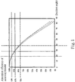
- Fig. 1 light incident angles and responses of a receiving element (or a chip) are illustrated.
- the chip has efficiency response of 100% when the angle of the light beam incident to the chip is zero degree (or defined as a perpendicular incidence), and the chip has efficiency response less than 87% when the angle of the light beam incident to the chip is greater than thirty degrees.
- the efficiency loss of the chip can be reduced (or the absorption efficiency and the photoelectric conversion efficiency of the chip can be increased) when the angle of the light beam incident to the chip is possibly kept less than thirty degrees.
- the assembled structure and the related configurations and designs of the conventional primary and secondary optical elements shall be rearranged and considered. It shall be known how to arrange and design to reduce the loss of the incident light (or the sunlight incident to the chip) when the angle of the light beam incident to the chip is kept less than thirty degrees.
- the purpose of the present invent is to provide a light-collecting device and a light-collecting method thereof, capable of providing a simple combination structure, guiding light beams to be almost perpendicularly entered into a receiving element, and increasing the absorption efficiency of a light-receiving element.
- the light-collecting device includes a light concentrator provided with a focusing (point) region and a light collector provided with total internal reflection and assembled with a light-receiving element.
- the light collector is defined with a light-entering aperture which is disposed near or located at the focusing region of the light concentrator and a light-radiating aperture.
- At least part of light beam received by the light concentrator travels through the focusing (point) region of the light concentrator and forwardly radiates to a light collector, and the light beam travelling form the light collector is incident to the receiving element when the light beam is optically functioned by the total internal reflection of the light collector, thereby improving the photoelectric conversion efficiency caused by large or imperfect light incident angles and non-uniform optical illumination in the conventional structures.
- the light collector is formed by type of (circular) conical geometry profile (section) with respect to a reference axis served as a datum.
- the light-entering aperture of the light collector is disposed near or located at the focusing region of the light concentrator or the range connected therewith, and the receiving element is disposed at the light-radiating aperture of the light collector.
- the light beam incident to the light collector can be possibly kept within an angular range which is almost perpendicular to the light-receiving element (or less than thirty degrees).
- the light collector is disposed on a base portion, and the base portion comprises an opening which is utilized to receive the light collector, disposed near or located at the focusing region of the light concentrator and defined by profiled (section) type with a wide top zone and a narrow bottom zone by taking the reference axis as a reference direction. Therefore, the focusing region of the light concentrator is located near or at the top zone of the opening of the base portion, and the (light-entering) aperture of the light collector is located at the top zone of the opening of the base portion.
- the base portion is formed on the bottom of the light concentrator, and the opening of the base portion (or the bottom portion) is defined by type of conical profile (or trapezoid section) with a wide top zone and a narrow bottom zone, wherein the inner diameter of the top zone is greater than that of the bottom zone of the opening, and the inner diameter of the bottom zone of the opening of the bottom portion of the light concentrator is approximately equal to the outer diameter of the light-radiating aperture of the light collector.
- type of conical profile or trapezoid section
- the conical-type light collector capable of providing both vertical alignment and horizontal (right and left (or central)) alignment, it is particularly suitable for an operator to conveniently align the light collector with the bottom zone of the opening of the bottom portion, thus to assemble the light collector on the bottom portion (or the base portion).
- the opening of the base portion or the bottom portion comprises a surface or an inner surface coated with a layer of reflective film to form a reflective surface.
- the inner diameter of the bottom zone of the opening of the light concentrator or the inner diameter of the bottom zone of the opening of the base portion is approximately equal to the outer diameter or the length of the diagonal line of the (light-)receiving element.
- the optical design of inputting the light beam comprises the steps of: (a) providing the focusing (point) region of the light concentrator to receive at least part of light beam from a light source, and forwardly radiating the light beam traveled through the focusing region of the light concentrator to the light collector to form a first stage output light; and (b) optically functioning the first stage output light reached the light collector by total internal reflection of the light collector to radiate a second stage output light and the second stage output light reached a light-radiating aperture of the light collector entering into the (light-)receiving element.
- the optical design of inputting the light beam comprises the steps of: (a) providing a light concentrator comprising a focusing (point) region to receive at least part of light beam from a light source, and forwardly radiating the light beam travelling from the light concentrator onto the surface of an opening which is formed on a base portion (or a bottom portion) and provided with a surface after the light beam is deflected from the focusing region of the light concentrator; (b) radiating the light beam reflected from the surface of the opening of the base portion (or the bottom portion) to form a first stage output light; and (c) optically functioning the first stage output light reached a light collector by refraction and/or total internal reflection of the light collector to radiate a second stage output light and the second stage output light reached a light-radiating aperture of the light collector entering into the (light-)receiving element.
- Fig. 1 is a schematic view showing light incident angles and responses of a receiving element
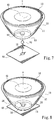
- Fig. 2 is a schematic view showing a structure of a light concentrator and a light collector of the present invention
- Fig. 3 is a schematic view showing an assembled structure of a light concentrator, a light collector and a base portion of the present invention
- Fig. 4 is a schematic view showing an assembled structure of a light concentrator of the present invention, wherein the light concentrator adopts a total internal reflection focal optical element;
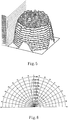
- Fig. 5 is a schematic view showing the illumination distribution of a light beam which travelling through a light concentrator in a primary optical process and a light collector in a secondary optical process;
- Fig. 6 is a schematic view showing the light intensity distribution of a light beam travelling through a light concentrator in a primary optical process and a light collector in a secondary optical process;
- Fig. 7 is a schematic view showing an exploded structure of a light concentrator and a light collector of the present invention.
- Fig. 8 is a schematic perspective view showing an assembled structure of a light concentrator and a light collector of the present invention.
- Fig. 9 is a cross-sectional view of the structure in Fig. 8 , wherein an imaginary line illustrates a top portion of a light collector which is formed by type of curved surface;
- Fig. 10 is a partially enlarged schematic view of the structure in Fig. 9 ;
- Fig. 11 is a schematic view of a light-collecting device of the present invention, illustrating the paths of guided light beams travelling through a light concentrator in a primary optical process and a light collector in a secondary optical process;
- Fig. 12 is a partially enlarged schematic view of the structure in Fig. 11 ;
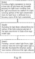
- Fig. 13 is a schematic block diagram of a light-collecting method for a light-collecting device of the present invention.
- Fig. 14 is a schematic view of a light-collecting device of the present invention, illustrating the travelling paths of the deflected light beams incident to the light-collecting device;
- Fig. 15 is a partially enlarged schematic view of the structure in Fig. 14 ;
- Fig. 16 is a schematic block diagram of another light-collecting method for a light-collecting device of the present invention.
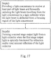
- Fig. 17 is a schematic block diagram of still another light-collecting method for a light-collecting device of the present invention.
- a light-collecting device of the present invention comprises an assembly of a light concentrator and a light collector, which are represented by number references 10 and 20, respectively.
- the light concentrator 10 defined as a primary optical element comprises a focusing region 15. At least part of light beam received by the light concentrator 10 travels through the focusing region 15 of the light concentrator 10 and forwardly radiates to a light collector 20, and the light beam travelling form the light collector 20 is incident to a (light-)receiving element 50 when the light beam is optically functioned or processed by the light collector 20 with total internal reflection.
- the light collector 20 is optically designed of total internal reflection and defined as a secondary optical element.
- the light collector 20 is a light-transmissive and solid element formed by type of conical geometry profile shown by the section in Fig. 2 with respect to a reference axis 'x' served as a datum, and it is understood that the structural section formed by type of conical profile has a curve with a curvature of zero, i.e., a slanted line.
- the light collector 20 comprises a light-entering aperture 22 and a light-radiating aperture 24, wherein the light-entering aperture 22 is disposed near or at the focusing region 15 or the range connected therewith, and the receiving element 50 is disposed at the light-radiating aperture 24.
- the receiving element 50 is arranged on a base plate 60 which is made of ceramic, copper or other similar materials, as described in Fig. 2 .
- the receiving element 50 and the base plate 60 are bonded to each other by a solder or tin paste therebetween, and the light collector 20 can be directly enclosed or packaged on the receiving element 50.
- the width or diameter of the light-entering aperture 22 is less than that of the light-radiating aperture 24.
- the light collector 20 is formed by a structure type with a narrow top portion and a wide bottom portion so that the light beam incident to the light collector 20 can be possibly kept within an angular range which is almost perpendicular to the light-receiving element 50 or less than thirty degrees, thereby increasing the absorption efficiency and the illumination uniformity of the light-receiving element 50, and the related contents will be described in detail hereinafter.
- the light collector 20 is disposed on a base portion 30 which can be integrally formed with the base plate 60 or can be fixedly bonded to the base plate 60 via an adhesive therebetween.
- the base portion 30 comprises or is defined with an opening 31 utilized to receive the light collector 20 therein, wherein the opening 31 is located near the focusing region 15 of the light concentrator 10 or the range connected therewith.
- the opening 31 of the base portion 30 is defined by type of structural profile or section with a wide top zone 31a and a narrow bottom zone 31b. That is, from the section of the base portion 30 in Fig.
- the width or diameter of the top zone 31a is greater than that of the bottom zone 31b.
- the focusing region 15 of the light concentrator 10 is located near or at the top zone 31a of the opening 31 of the base portion 30, and the light-entering aperture 22 of the light collector 20 is located at the top zone 31a of the opening 31 of the base portion 30.
- the opening 31 of the base portion 30 comprises a surface or an inner surface 31c coated with a layer of reflective film to form a reflective surface. It is needed to explain that, with the opening 31 of the base portion 30 defined with the wide top zone 31a and the narrow bottom zone 31b, an acceptance angle of the optical system can be increased.
- the light beam incident to the light collector 20 can be incident to the light-receiving element 50 at a small angle (e.g., within thirty degrees as mentioned above); moreover, incorporated the top zone 31a, the bottom zone 31b and the surface 31c of the opening 31 of the base portion 30, the acceptance angle of the optical system can also be increased.
- the light concentrator 10 adopts a total internal reflection (TIR) focal optical element having the focusing region 15, providing a structural type capable of matching the light collector 20, the base portion 30, and the opening 31 of the base portion 30, i.e., the light-entering aperture 22 of the light collector 20 is located at the focusing region 15 of the light concentrator 10.
- the focal optical element can be selected from Fresnel lens, TIR refractive lens or other similar optical systems.
- Fig. 4 shows the condition that the incident light beam or sunlight being type of perpendicular incidence travels through the light concentrator 10 in a primary optical process and the light collector 20 in a secondary optical process.
- the incident light beam travelling through a middle part of the light concentrator 10 is denoted by a reference numeral '71'
- the incident light beam travelling through a peripheral part of the light concentrator 10 is denoted by a reference numeral '72'.
- the light beam 71 travelling through the light concentrator 10 is directly guided to the focusing region 15 of the light concentrator 10 to enter into the light collector 20 via the light-entering aperture 22 thereof, and then the light beam is uniformly and collectively incident to the light-receiving element 50, i.e., the refracted light beam 71 from the light concentrator 10 directly enters into the light-receiving element 50 without being functioned by the total internal reflection of the light collector 20.
- the light beam 72 entering the light concentrator 10 is guided by a serrated structure of the light concentrator 10 to the focusing region 15 of the light concentrator 10, the guided light beam 72 is radiated from the light-entering aperture 22 of the light collector 20 to form a first stage output light, and then the first stage output light is optically functioned by the total internal reflection of the light collector 20 to be uniformly incident to the light-receiving element 50.
- the angular range of the light beams 71 and 72 incident to the light-receiving element 50 is kept within from zero to thirty degrees (or approximately from zero to forty degrees).
- the light beams 71 and 72 are incident to the light-receiving element 50 in an almost perpendicular way or within the angular range less than thirty degrees. According to the experimental simulations in Figs. 5 and 6 , it is proved that this embodiment can provide perfect features of a small light incident angle to the light-receiving element 50, illumination uniformity and light intensity distribution, compared to the conventional skills.
- Fig. 7 shows an exploded structure of a light concentrator 10 and a light collector 20 of another specific embodiment of the present invention
- Fig. 8 shows an assembled structure of the light concentrator 10 and the light collector 20.
- the light concentrator 10 having a reflective surface or curved surface 11 is a reflective optical design or an optical reflective mapping element.
- the reflective surface 11 of the light concentrator 10 is provided with a reflective layer made of reflective material.
- the reflective surface 11 of the light concentrator 10 can be selected from a metallic surface reflective layer or a structure made of other materials capable of providing reflective effects.
- the volume of the light concentrator 10 is obviously greater than that of the light collector 20.
- the light collector 20 is arranged at a bottom portion 13 of the light concentrator 10, and the light collector 20 and the light concentrator 10 are assembled to each other via a bonding structure or integrally formed.
- the light concentrator 10 comprises a light-entering aperture 12 and an opening 14 (referred to 'light-radiating aperture') which is formed on the bottom portion 13 and located at the other end or an opposite side of the light-entering aperture 12, allowing to output the light beam via the opening 14.
- the light collector 20 is substantially received in or disposed at the opening 14 of the light concentrator 10 or inside a region where the opening 14 of the light concentrator 10 is located. Therefore, it is preferably considered that the height of the light collector 20 is approximately equal to the thickness of the bottom portion 13, as shown in Fig. 9 .
- a reference axis 'x' is served as a datum for the light concentrator 10 or for the reflective surface 11 of the light concentrator 10, and the light concentrator 10 is formed by type of dome profile, parabolic profile or other profiles.
- the light concentrator 10 adopts type of parabolic profile or section, so that the reflective surface 11 of the light concentrator 10 is formed by type of curved surface defining the focusing region 15, and the opening 14 is located near or at the focusing region 15. Therefore, the light-entering aperture 22 of the light collector 20 is located near or at the focusing region 15.
- the light-entering aperture 12 of the light concentrator 10 is disposed with a secondary light-concentrating element 40 which is selected from Fresnel lens, TIR refractive lens or other similar optical systems, allowing to output the light beam via the focusing region 15 of the light concentrator 10.
- a secondary light-concentrating element 40 which is selected from Fresnel lens, TIR refractive lens or other similar optical systems, allowing to output the light beam via the focusing region 15 of the light concentrator 10.
- the embodiment in Fig. 9 utilizes the bottom portion 13 to serve as or replace the base portion 30 of the embodiment in Fig. 4 . More specifically, by taking the reference axis 'x' as a reference direction, the opening 14 of the bottom portion 13 of the light concentrator 10 is formed by type of conical profile or trapezoid section.
- the opening 14 of the bottom portion 13 is defined by type of structural profile or section with a wide top zone 14a and a narrow bottom zone 14b, which is similar to the structure of the opening 31 of the base portion 30. That is, from the section in Fig. 9 or Fig.
- the width or inner diameter of the top zone 14a is greater than that of the bottom zone 14b of the opening 14 of the bottom portion 13 of the light concentrator 10, and the width or inner diameter of the bottom zone 14b of the opening 14 of the bottom portion 13 of the light concentrator 10 (or the bottom zone 31b of the opening 31 of the base portion 30 in Fig. 4 ) is approximately equal to or slightly greater than the width or outer diameter of the light-radiating aperture 24 of the light collector 20.
- the conical-type light collector 20 formed with the narrow top portion and the wide bottom portion and similarly functioned as a guiding post capable of providing both vertical alignment and horizontal (or right and left (or central)) alignment, it is particularly suitable for an operator to conveniently align the light collector 20 with the bottom zone 14b of the opening 14 of the bottom portion 13 for insertion, thus to assemble the light collector 20 and the light concentrator 10 as shown in Fig. 10 .
- the opening 14 of the light concentrator 10 comprises a surface or an inner surface 14c coated with a layer of reflective film to form a reflective surface capable of increasing the acceptance angle of the optical system, and the related contents will be described in detail hereinafter.
- the inner diameter of the bottom zone 14b of the opening 14 of the light concentrator 10 or the inner diameter of the bottom zone 31b of the opening 31 of the base portion 30 is approximately equal to the outer diameter or the length of the diagonal line of the receiving element 50.
- the receiving element 50 and the base plate 60 are bonded to each other by a solder or tin paste therebetween, and an adhesive is applied between the bottom portion 13 of the light concentrator 10 and the base plate 60 to bond the light concentrator 10 and the base plate 60.
- the area or volume of the base plate 60 can be altered according to the actual requirements or the conditions on the job sites.
- a top portion surface (or a boundary surface) or the light-entering aperture 22 of the light collector 20 is formed by type of curved surface 23 shown by an imaginary line.
- the reflection loss of the large-angled incident light beam can be possibly reduced when reaching the light collector 20, compared to a light collector with a plane surface.
- the height (or position) of the light collector 20 can be slightly lower or higher than the height (or position) of the opening 14 of the light concentrator 10 and the opening 31 of the base portion 30.
- the width (or the inner diameter) of the bottom zone 14b of the opening 14 of the light concentrator 10 is approximately equal to or slightly greater than the width (or the outer diameter) of the receiving element 50; the width (or the inner diameter) of the bottom zone 14b of the opening 14 of the light concentrator 10 (or the bottom zone 31b of the opening 31 of the base portion 30) is approximately equal to or slightly greater than the length of the diagonal line of the receiving element 50; the width (or the inner diameter) of the (light-radiating) aperture 24 of the light collector 20 is approximately equal to the width (or the outer diameter) of the receiving element 50; and the width (or the inner diameter) of the (light-radiating) aperture 24 of the light collector 20 is approximately equal to the length of the diagonal line of the receiving element 50.
- Figs. 11 and 12 show the condition that the incident light beam or sunlight being type of perpendicular incidence travels through the light concentrator 10 in a primary optical process and the light collector 20 in a secondary optical process.
- the incident light beam travelling through a secondary light-concentrating element 40 is denoted by a reference numeral ⁇ 71'
- the incident light beam not travelling through the secondary light-concentrating element 40 is denoted by a reference numeral ⁇ 72'.
- the light beam 71 travelling through the secondary light-concentrating element 40 is directly guided to the focusing region 15 of the light concentrator 10 to enter into the light collector 20 via the opening 14 of the light concentrator 10 (or the light-entering aperture 22 of the light collector 20), and then the light beam entered into the light collector 20 is uniformly incident to the light-receiving element 50 at an angle almost perpendicular to the light-receiving element 50.
- the light beam 72 entering the light concentrator 10 is reflected by the reflective surface 11 of the light concentrator 10 and travelled through the focusing region 15 of the light concentrator 10, and then the light beam 72 travelling from the focusing region 15 of the light concentrator 10 is radiated from the opening 14 of the light concentrator 10 (or the light-entering aperture 22 of the light collector 20) to form a first stage output light, and then the first stage output light is optically functioned by the total internal reflection of the light collector 20 to be uniformly incident to the light-receiving element 50.
- the optical design of inputting the light beam comprises the steps of:
- the opening 14 of the light concentrator 10 comprises the surface or inner surface 14c coated with the reflective film to form the reflective surface.
- a deviation (or deflection angle) phenomenon is occurred when the angle of the light beam or sunlight incident to the light-collecting device belongs to a type of non-straight direction.
- Figs. 11 and 12 it can be seen that in Figs.
- a partial light beam 71a refracted from the secondary light-concentrating element 40 travels through the opening 14 of the light concentrator 10 and crosses the light collector 20 (or the focusing region 15 of the light concentrator 10) to radiate to and reflect from the surface 14c (or the reflective surface) of the opening 14, thus to form a first stage output light.
- the first stage output light reaching the light collector 20 is optically functioned by total internal reflection of the light collector 20 to radiate a second stage output light, and the second stage output light reaching the light-radiating aperture 24 of the light collector 20 is incident to the (light-)receiving element 50.
- a partial light beam 71b refracted from the secondary light-concentrating element 40 is deflected from the focusing region 15 of the light concentrator 10 to directly radiate to the light collector 20 and then to enter into the (light-)receiving element 50.
- a partial light beam 72a formed therefrom travels through the opening 14 of the light concentrator 10 and crosses the light collector 20 (or the focusing region 15 of the light concentrator 10) to radiate to and reflect from the surface 14c (or the reflective surface) of the opening 14, thus to form a first stage output light.
- the first stage output light reaching the light collector 20 is optically functioned by refraction and/or total internal reflection of the light collector 20 to radiate a second stage output light, and the second stage output light reaching the light-radiating aperture 24 of the light collector 20 is incident to the (light-)receiving element 50.
- a partial light beam 72b reflected from the reflective surface 11 of the light concentrator 10 is deflected from the focusing region 15 of the light concentrator 10 to directly radiate to and to be optically functioned by refraction and/or total internal reflection of the light collector 20, and then to enter into the (light-)receiving element 50.
- the partial light beams 71a, 71b, 72a and light beam 72b crossing the light collector 20 makes a very small impact on the total light-collecting efficiency or light-collecting proportion, but the light-collecting device of the above-described embodiment provided with a large acceptance angle of the optical system still can allow the processed light beams, which are formed after the partial light beams 71a, 71b, 72a and 72b is optically functioned via the reflective surface 11 or the surface or inner surface 14c of the opening 14 of the light concentrator 10 and then optically functioned by the refraction/reflection of the light collector 20, to enter into the (light-)receiving element 50.
- the light-collecting device of the above-described embodiment is not only provided with perfect features of the small light incident angle to the light-receiving element 50, illumination uniformity and light intensity distribution, but also is featured with an optical function of larger acceptance angle of the optical system.
- the light-collecting device of the present invention further comprises another light-collecting method for the light-collecting device.
- the optical design of inputting the light beam comprises the steps (a), (b) and (c) as follows.
- the focusing region 15 of the light concentrator 10 is provided to receive at least part of light beam from a light source, and the light beam travelling from the light concentrator 10 is forwardly radiated to the surface 14c of an opening 14 of the light concentrator 10 after the light beam is deflected from the focusing region 15 of the light concentrator 10.
- the light concentrator 10 receiving at least part of the light beam, it means that the light beams, which include the light beam 71a travelling through the secondary light-concentrating element 40 and the light beam 72a reflected by the reflective surface 11 of the light concentrator 10, are formed by type of deflection angle to enter into the light concentrator 10, relative to the reference axis 'x' as a reference direction.
- the light-collecting device of the present invention further comprises another light-collecting method for the light-collecting device.
- the optical design of inputting the light beam comprises the steps (a) and (b) as follows.
- the light concentrator 10 is provided to receive at least part of light beam from a light source, and the light beam travelling from the light concentrator 10 is forwardly radiated to the light collector 20 to form a first stage output light after the light beam is deflected from the focusing region 15 of the light concentrator 10.
- the light concentrator 10 receiving at least part of the light beam, it means that the light beams, which include the light beam 71b travelling through the secondary light-concentrating element 40 and the light beam 72b reflected by the reflective surface 11 of the light concentrator 10, are formed by type of deflection angle to enter into the light concentrator 10, relative to the reference axis 'x' as a reference direction.
- the light collector 20 can be considerably formed by type of parabolic profile or section (not shown in Figs.) comprising a focusing (point) region and a light-entering aperture 22 formed at the focusing (point) region, wherein the focusing (point) region of the light collector 20 and the focusing region 15 of the light concentrator 10 are formed by a confocal (point) type or are approximately formed by a confocal type within a range, and the light-entering aperture 22 of the light collector 20 is approximately located at the top zone 14a of the opening 14 of the bottom portion 13 or the focusing region 15 of the light concentrator 10.
- the light collector 20 is also defined with a light-radiating aperture 24 relative to the other side or the opposite side of the light-entering aperture 22.
- the receiving element 50 is disposed on the light-radiating aperture 24 of the light collector 20.
- the traveling condition of the light beam of this derivative embodiment is similar to the paths of the light beams in Figs. 11, 12 , 14 and 15 .
- the focusing (point) region through which the light beam travels can be inclusively defined by a confocal (point) type or is approximately defined by a confocal type, wherein the focusing (point) region is referred to the confocal region or range of the focusing region 15 of the light concentrator 10 and the focusing region of the light collector.
- the light-collecting device and the light-collecting method thereof in the present invention provide a simplified structure based on the design considerations as follows.
- the assembled structure of the light-collecting device in the design and manufacturing processes is simplified, capable of reducing the manufacturing cost and increasing the accuracies of the light-concentrating element and the light receiving element, increasing the stabilities of the conversion performance and generator efficiency of the light-collecting device, and improving the illumination uniformity of conventional structures to increase the photoelectric conversion efficiency.
- the light-collecting device of the present invention shall be provided with the structural features as follows.
- the light collector 20 shall have the profile or section formed by the structure type with the narrow top portion and the wide bottom portion so that the light beams incident to the light collector 20 can be possibly kept within an angular range which is almost perpendicular to (i.e., zero degree) the light-receiving element 50, thereby attaining uniform illumination distribution of the light-receiving element 50.
- the diameter of the bottom zone 14b of the opening 14 of the bottom portion 13 of the light concentrator 10 is approximately equal to or slightly greater than the outer diameter of the light collector 20, or the diameter of the bottom zone 14b of the opening 14 of the bottom portion 13 of the light concentrator 10 (or the bottom zone 31b of the opening 31 of the base portion 30) is approximately equal to or slightly greater than the outer diameter (or the length of the diagonal line) of the receiving element 50.
- the light collector 20 similarly formed as the guiding post, the alignment and assembly processes of the light collector 20 and the light concentrator 10 in vertical and horizontal (or central) directions can be facilitated.
- the light concentrator 10 and the base portion 30 particularly adopt the internal reflection optical elements which have the openings 14 and 31 respectively defined by structural type with the wide top zone and the narrow bottom zone, so that a large acceptance angle can be provided to guide the light beam into the light-receiving element 50 even though the deflected light beam is incident to the light-collecting device.
- the reflective surface formed the surface or inner surface 14c of the opening 14 of the light concentrator 10 and the reflective layer coated on the reflective surface 11 of the light concentrator 10 can be completed in the same process, thereby increasing the efficiency of film-coating processes and obtaining ideal film thickness uniformity, compared to the individual or different processes in conventional skills.
- the light-collecting device of the present invention it is particularly and considerably to incorporate the angle design of the light beam incident to the receiving element 50 (or a chip) into the configuration design of the primary optical process of the light concentrator 10 and the secondary optical process of the light collector 20, which is much different from the conventional design only focusing on uniformity of the light beam incident to the receiving element (i.e., uniform light effect) or increment of acceptance angle of the receiving element.
- the angle of the light beam incident to the receiving element 50 is kept within an angular range less than thirty degrees, thereby reducing the efficiency loss of the receiving element 50 (or increasing the absorption efficiency and the photoelectric conversion effect of the chip).
- the light-collecting device of the present invention is capable of reducing the efficiency loss of the chip, and therefore the combination structure and related configuration design of the primary optical element (i.e., the light concentrator 10) and the secondary optical element (i.e., the light collector 20) shall be correspondingly rearranged and reconsidered.
- the inventive light-collecting device and the light-collecting method thereof in the present invention effectively provide unique functionalities and spatial type and are different from that in the conventional skills.
Landscapes
- Physics & Mathematics (AREA)
- General Physics & Mathematics (AREA)
- Optics & Photonics (AREA)
- Health & Medical Sciences (AREA)
- Life Sciences & Earth Sciences (AREA)
- Sustainable Development (AREA)
- Toxicology (AREA)
- Photovoltaic Devices (AREA)
- Optical Elements Other Than Lenses (AREA)
Applications Claiming Priority (1)
| Application Number | Priority Date | Filing Date | Title |
|---|---|---|---|
| TW100104786A TWI538239B (zh) | 2011-02-14 | 2011-02-14 | Light collection device and its light collection method |
Publications (1)
| Publication Number | Publication Date |
|---|---|
| EP2487728A2 true EP2487728A2 (fr) | 2012-08-15 |
Family
ID=45654944
Family Applications (1)
| Application Number | Title | Priority Date | Filing Date |
|---|---|---|---|
| EP12000871A Withdrawn EP2487728A2 (fr) | 2011-02-14 | 2012-02-10 | Dispositif de collecte de lumière et son procédé de collecte de lumière |
Country Status (4)
| Country | Link |
|---|---|
| US (1) | US20120206826A1 (fr) |
| EP (1) | EP2487728A2 (fr) |
| JP (1) | JP2012167921A (fr) |
| TW (1) | TWI538239B (fr) |
Families Citing this family (3)
| Publication number | Priority date | Publication date | Assignee | Title |
|---|---|---|---|---|
| CN112612014A (zh) * | 2020-11-27 | 2021-04-06 | 西安知微传感技术有限公司 | 一种高效能mems激光雷达接收系统 |
| EP4340216A4 (fr) * | 2021-05-14 | 2025-01-29 | Bolymedia Holdings Co. Ltd. | Dispositif d'utilisation d'énergie solaire et structure combinée de dispositif d'utilisation d'énergie solaire |
| CN113295271A (zh) * | 2021-05-26 | 2021-08-24 | 复旦大学 | 一种基于内全反射透镜的笔式集光器 |
Citations (3)
| Publication number | Priority date | Publication date | Assignee | Title |
|---|---|---|---|---|
| US6541694B2 (en) | 2001-03-16 | 2003-04-01 | Solar Enterprises International, Llc | Nonimaging light concentrator with uniform irradiance |
| US7473000B2 (en) | 2006-12-07 | 2009-01-06 | Solfocus, Inc. | Shield for solar radiation collector |
| US20090320923A1 (en) | 2005-10-28 | 2009-12-31 | Atomic Energy Council - Institute Of Nuclear Energy Research | Photovoltaic concentrating apparatus |
Family Cites Families (7)
| Publication number | Priority date | Publication date | Assignee | Title |
|---|---|---|---|---|
| US20080047605A1 (en) * | 2005-07-28 | 2008-02-28 | Regents Of The University Of California | Multi-junction solar cells with a homogenizer system and coupled non-imaging light concentrator |
| US8412010B2 (en) * | 2007-09-10 | 2013-04-02 | Banyan Energy, Inc. | Compact optics for concentration and illumination systems |
| US7980727B2 (en) * | 2008-10-07 | 2011-07-19 | Reflexite Corporation | Monolithic tiring condensing arrays and methods thereof |
| GB0911514D0 (en) * | 2009-07-02 | 2009-08-12 | The Technology Partnership Plc | Solar concentrator |
| US20120006382A1 (en) * | 2010-06-07 | 2012-01-12 | Hypersolar, Inc. | Thin and flat solar collector-concentrator |
| WO2012058304A2 (fr) * | 2010-10-28 | 2012-05-03 | Banyan Energy, Inc. | Éléments optiques de réorientation destinés à des systèmes de concentration et d'éclairage |
| US8885995B2 (en) * | 2011-02-07 | 2014-11-11 | Morgan Solar Inc. | Light-guide solar energy concentrator |
-
2011
- 2011-02-14 TW TW100104786A patent/TWI538239B/zh not_active IP Right Cessation
- 2011-07-29 JP JP2011167086A patent/JP2012167921A/ja not_active Withdrawn
-
2012
- 2012-02-10 US US13/370,556 patent/US20120206826A1/en not_active Abandoned
- 2012-02-10 EP EP12000871A patent/EP2487728A2/fr not_active Withdrawn
Patent Citations (3)
| Publication number | Priority date | Publication date | Assignee | Title |
|---|---|---|---|---|
| US6541694B2 (en) | 2001-03-16 | 2003-04-01 | Solar Enterprises International, Llc | Nonimaging light concentrator with uniform irradiance |
| US20090320923A1 (en) | 2005-10-28 | 2009-12-31 | Atomic Energy Council - Institute Of Nuclear Energy Research | Photovoltaic concentrating apparatus |
| US7473000B2 (en) | 2006-12-07 | 2009-01-06 | Solfocus, Inc. | Shield for solar radiation collector |
Also Published As
| Publication number | Publication date |
|---|---|
| JP2012167921A (ja) | 2012-09-06 |
| US20120206826A1 (en) | 2012-08-16 |
| TWI538239B (zh) | 2016-06-11 |
| TW201234631A (en) | 2012-08-16 |
Similar Documents
| Publication | Publication Date | Title |
|---|---|---|
| US8119905B2 (en) | Combination non-imaging concentrator | |
| CN102216695B (zh) | 用于太阳能采集的系统和方法及相关的制造方法 | |
| US9086227B2 (en) | Method and system for light collection and light energy converting apparatus | |
| US20080066799A1 (en) | Optical Concentrator for Solar Cell Electrical Power Generation | |
| US20090000612A1 (en) | Apparatuses and methods for shaping reflective surfaces of optical concentrators | |
| WO2006132265A1 (fr) | Unité et système de batterie solaire à condensation, lentille de condensation, structure de lentille de condensation et procédé de production de structure de lentille de condensation | |
| JP6416333B2 (ja) | 太陽電池モジュール | |
| WO2013147008A1 (fr) | Lentille secondaire, corps de montage de cellule solaire, unité d'énergie solaire de collecte de lumière, dispositif d'énergie solaire de collecte de lumière et module d'énergie solaire de collecte de lumière | |
| US20130104984A1 (en) | Monolithic photovoltaic solar concentrator | |
| US20080128016A1 (en) | Parallel Aperture Prismatic Light Concentrator | |
| ITBO20100541A1 (it) | Sistema fotovoltaico con concentratore solare a doppia riflessione | |
| US8847142B2 (en) | Method and device for concentrating, collimating, and directing light | |
| US8817377B2 (en) | Light collection system and method | |
| RU2611693C1 (ru) | Солнечный концентраторный модуль | |
| JP2013211487A (ja) | 二次レンズ、太陽電池実装体、集光型太陽光発電ユニット及び集光型太陽光発電モジュール | |
| US20140090692A1 (en) | Concentrated solar cell and manufacturing method for the same | |
| EP2487728A2 (fr) | Dispositif de collecte de lumière et son procédé de collecte de lumière | |
| RU2436192C1 (ru) | Фотоэлектрический модуль с наноструктурным фотоэлементом | |
| JP2006332113A (ja) | 集光型太陽光発電モジュール及び集光型太陽光発電装置 | |
| JP2006343435A (ja) | 集光レンズ、集光レンズ構造体、集光型太陽光発電装置、および集光レンズ構造体の製造方法 | |
| TWI693787B (zh) | 平板式集光裝置 | |
| JP2014010251A (ja) | 二次レンズ、太陽電池実装体、集光型太陽光発電装置、および集光型太陽光発電モジュール | |
| JP6530257B2 (ja) | 太陽光集光モジュールおよびそれを用いた集光パネル | |
| US20110000538A1 (en) | Non-imaging solar concentrator reflector for photovoltaic cells | |
| CN102654636B (zh) | 集光装置及其集光方法 |
Legal Events
| Date | Code | Title | Description |
|---|---|---|---|
| PUAI | Public reference made under article 153(3) epc to a published international application that has entered the european phase |
Free format text: ORIGINAL CODE: 0009012 |
|
| AK | Designated contracting states |
Kind code of ref document: A2 Designated state(s): AL AT BE BG CH CY CZ DE DK EE ES FI FR GB GR HR HU IE IS IT LI LT LU LV MC MK MT NL NO PL PT RO RS SE SI SK SM TR |
|
| AX | Request for extension of the european patent |
Extension state: BA ME |
|
| STAA | Information on the status of an ep patent application or granted ep patent |
Free format text: STATUS: THE APPLICATION IS DEEMED TO BE WITHDRAWN |
|
| 18D | Application deemed to be withdrawn |
Effective date: 20150901 |