EP2487731A1 - Composite doté d'un conducteur revêtu - Google Patents
Composite doté d'un conducteur revêtu Download PDFInfo
- Publication number
- EP2487731A1 EP2487731A1 EP11305136A EP11305136A EP2487731A1 EP 2487731 A1 EP2487731 A1 EP 2487731A1 EP 11305136 A EP11305136 A EP 11305136A EP 11305136 A EP11305136 A EP 11305136A EP 2487731 A1 EP2487731 A1 EP 2487731A1
- Authority
- EP
- European Patent Office
- Prior art keywords
- temperature superconductor
- composite
- coated conductor
- fault current
- composites
- Prior art date
- Legal status (The legal status is an assumption and is not a legal conclusion. Google has not performed a legal analysis and makes no representation as to the accuracy of the status listed.)
- Withdrawn
Links
Images



Classifications
-
- H—ELECTRICITY
- H10—SEMICONDUCTOR DEVICES; ELECTRIC SOLID-STATE DEVICES NOT OTHERWISE PROVIDED FOR
- H10N—ELECTRIC SOLID-STATE DEVICES NOT OTHERWISE PROVIDED FOR
- H10N60/00—Superconducting devices
- H10N60/30—Devices switchable between superconducting and normal states
-
- H—ELECTRICITY
- H01—ELECTRIC ELEMENTS
- H01B—CABLES; CONDUCTORS; INSULATORS; SELECTION OF MATERIALS FOR THEIR CONDUCTIVE, INSULATING OR DIELECTRIC PROPERTIES
- H01B12/00—Superconductive or hyperconductive conductors, cables, or transmission lines
- H01B12/02—Superconductive or hyperconductive conductors, cables, or transmission lines characterised by their form
Definitions
- the present invention relates to the field of high-temperature superconductor (hts) coated conductors.
- the present invention relates to a composite with a coated conductor suitable as a prefabricated hts component, for example in a fault current limiter.
- Coated conductors which are also referred to as “second generation superconductors", typically have a long length as required for example in the production of cables and wires.
- buffer layer(s) serve to compensate for the various different properties of the materials used.
- buffer layer(s) can be provided for preventing poisoning of the hts-layer by constitutional elements of the substrate which might diffuse toward the hts-layer.
- one or more further layers can be provided.
- a metal protection layer can be deposited onto the hts-layer.
- Superconductor materials are characterized in that they have zero resistance when operated below a certain temperature (the critical temperature Tc) and external magnetic field (the critical magnetic field Hc) if the current flowing through the superconductor material is below a certain threshold value (critical current Ic).
- the critical current, critical temperature and critical magnetic field are specific for a given superconductor material. However, if any of these parameters is exceeded, the superconductor material suddenly loses its superconducting properties and behaves like a "normal" resistor, it is said the material quenches.
- High-temperature superconductors having a Tc above the temperature of 30 K are generally referred to as high-temperature superconductors.
- Particularly preferred high-temperature superconductors are those having a Tc greater than the boiling point of liquid nitrogen (77 K or -196 °C) which allows cooling with liquid nitrogen, a cheap and easily available cooling medium.
- high-temperature superconductors with a critical temperature above 77 K are those known as ceramic oxide high-temperature superconductors, such as those based on rare earth metal (RE inclusive Y), Bi, TI and Hg.
- RE means at least one rare-earth element, particularly Y or a combination of two or more of the elements Y, La, Lu, Sc, Sm, Nd or Yb.
- a preferred member thereof is that one known by the reference YBCO-123 wherein the numerical combination 123 stands for the stoichiometric ratio of the elements Y, Ba and Cu.
- Coated conductors are promising candidates for a plurality of electrical applications such as high and medium voltage power transmission cables, wire applications, transformers, magnets (for example, for magnetic resonance imaging), synchronous motors with superconducting windings and fault current limiters.
- superconductor fault current limiters are devices that automatically limit fault current in high-voltage networks to a low current value close to the nominal current.
- the benefit of such a device is that it reduces drastically the short circuit power of the high-voltage network and, thus, allows to interconnect networks without increasing the short circuit power or to decrease safety margins so that other machineries connected to the network can be designed for lower short short circuit power and, therefore, can be made lighter and cheaper.
- Superconductor fault current limiters make use of the property of superconductor material to have virtually no electrically resistance when operated below the critical temperature-even at nominal power loads. However, if the critical current (above the nominal current) is exceeded, the material suddenly loses its superconducting properties and behaves like a "normal" resistor. This relatively high resistance limits the current to a pre-defined value. In many applications, such as in fault current limiters, a long length of coated conductor is required and need winding of the coated conductor. However, there is a number of problems associated with the winding of a long length of coated conductor for obtaining, for example, a practically useful switching module for a fault current limiter.
- the winding should be spatially compact for allowing space saving accommodation.
- typical bending radii are in a range of 20 to 50 mm.
- the coated conductor should be preferably in direct contact with the cooling medium.
- the superconductor is heated up to a temperature of 300 K or more in the course of quench. For the fault current limiter to be ready for use again rapid cooling back to the operational temperature is therefore necessary.
- fault current limiters should be used at high-voltage levels in a range of between 10 kV to above 100 kV, typically, a very long length of coated conductor is needed. Otherwise, the fault current limiter which is to be interconnected into an electrical application should be as small as possible to save space. Thus, there is a need, to place a long length of coated conductor within the cryostat housing with minimum space requirements to keep the overall cryostat housing as small as possible.
- the hts material should have a configuration with an inductance as small as possible. Inductance generates fields causing high Lorentz forces which exert mechanical stress on the hts component. Moreover, increasing fields lead to a significant decrease of the current carrying capacity of the hts material.
- the present invention provides a composite wherein a coated conductor is embedded within an electrically insulating material.
- the electrically insulating material is preferably a prepreg.
- the present invention provides a composite wherein a coated conductor is arranged onto or embedded into an electrically insulating material.
- a coated conductor is a tape shaped article of long length, which means that the longitudinal extension significantly exceeds the width or diameter.
- a coated conductor tape or “tape-shaped coated conductor”.
- the tape-shaped coated conductor can have an essentially rectangular or essentially round cross-sectional shape.
- Essentially rectangular or “essentially round” means that the cross-sectional shape may deviate from an ideal rectangular or round shape, for example being trapezoid or oval. It is also possible to use a coated conductor wherein the substrate is coated on both sides with a hts-layer and buffer layer(s). Further, in case of an essentially round coated conductor, typically the layers and the substrate are coaxially arranged onto the substrate.
- Coated conductors their configuration and production methods thereof are well known in the art.
- one or more tape-shaped coated conductor can be arranged onto or into the insulating material.
- the individual coated conductors arranged onto or into the insulating material can be connected electrically in parallel and/or in series.
- the composite of the present invention provides a coated conductor component which can be pre-fabricated and allows modular and standardisized configuration. For example, in a composite a number of m tape-shaped coated conductor can be arranged onto an insulating material and connected electrically in parallel. In the result, the available length of coated conductor can be easily varied by varying the number of composites electrically connected in series. Depending on the operation parameters for a fault current limiter the required number of I of such individual composites can be placed within the cryostat and connected electrically in series for obtaining a desired length of coated conductor.
- the number of coated conductors of an individual composite can be varied according to need and particular dimension of the individual composite.
- the insulating material bearing or having embedded the coated conductor can have any suitable shape.
- shapes are possible having surface area which is rectangular, polygonal, round, elliptical etc. Examples thereof is a plate, strip or disc.
- the electrical insulating material can be any such material conventionally used in the production of high-temperature superconductor devices such as hts fault current limiters and cables.
- the insulating material is used in a pre-fabricated product, such as a fault current limiter component, which is ready to be mounted in a hts device, such as a fault current limiter.
- Suitable examples of such insulating materials are cold resistant plastics, epoxy resin etc.
- the electrically insulating material is a prepreg.
- Prepregs as such are also well known.
- any commercially available prepreg can be used.
- Prepregs are semi-finished articles and are composed of fiber-reinforced plastics which are impregnated with a non-hardened resin. After arranging the coated conductor onto or into the prepreg hardening is carried out by heating to a suitable temperature, for example about 100 °C.
- prepregs which can be used are those, wherein glass, aramide, carbon or graphite fibers are impregnated with epoxy-, polyester-, or phenole resins.
- the high temperature superconductor layer of a coated conductor must have a high degree of crystallographic orientation to allow the current to be transferred across the crystallites.
- the individual crystallites of the layer should be tilted against one another only by a minimum value, since otherwise superconducting properties are severely impaired.
- a highly-textured buffer layer is deposited onto a polycrystalline, randomly oriented substrate by direct physical coating processes such as ion beam assisted deposition (IBAD) and inclined substrate deposition (ISD).
- IBAD ion beam assisted deposition
- ISD inclined substrate deposition
- the highly textured buffer layer serves to transfer the desired texture to the superconductor layer grown onto the buffer layer.
- a highly-textured substrate is used which can be obtained by mechanical working, for example by RABiTS (rolling assisted biaxial texturing of substrates).
- RABiTS rolling assisted biaxial texturing of substrates
- the texture of the substrate is transferred to the buffer layer, and, then, to the superconductor layer deposited thereon.
- metals suitable as substrate are copper, nickel, silver, iron and alloys thereof.
- Suitable buffer layer materials are lanthanum-zirconate, cerium oxide, yttrium-stabilized zirconia (YSZ), gadolinium-zirconate, yttrium oxide, rare earth aluminates such as lanthanum-aluminate, strontiumtitanate, nickel oxide, magnesium oxide, oxides of general formular RE 2 A 2 O 7 with RE as defined above and A being selected from Zr and Hf, in particular La 2 Zr 2 O 7 (LZO, lanthanum-zirconate) and many others.
- YSZ yttrium-stabilized zirconia
- the high-temperature superconductor is a ceramic oxide high temperature superconductor selected from the group consisting of bismuth-based, thallium-based, rare earth metal based, and mercury-based superconductor ceramic oxides.
- Typical examples thereof comprise ceramic oxide superconductors based on Bi-Ae-Cu-Oy, (Bi, Pb)-Ae-Cu-O y , Re-Ae-Cu-O y , TI-Ae-Cu-O y or Hg-Ae-Cu-O y wherein y represents the relative oxygen content in the range appropriate for the particular superconductor material to have superconducting property.
- Ae means at least one alkaline earth element, particularly, Ba, Ca and/or Sr.
- RE is as defined as above with respect to the REBa 2 Cu 3 O 7-x material.
- the high temperature superconductor ceramic oxide is of the type RE-Ae-Cu 3 -O 7-x with Re, Ae and x being defined as above.
- the high-temperature superconductor ceramic oxide is type RE, Ba 2 Cu 3 O 7-x with RE and x being defined as above. More preferably the high-temperature superconductor ceramic oxide is of type YBCO-123.
- suitable deposition techniques of the hts layer as well as of buffer layers for example those referred to above are pulsed laser deposition, thermal co-evaporation, chemical vapor deposition, chemical solution deposition, such as metal organic deposition, sol gel methods and many others.
- a composite 1 of the present invention is shown wherein a tape-shaped coated conductor 2 is attached onto a support 3 made of electrically insulating material (also referred to "insulating support") At each end of the tape-shaped coated conductor 2 an electrical contact 4 is provided for connecting the tape-shaped coated conductor 2 electrically with the surrounding.
- the tape-shaped coated conductor 2 extends over the whole longitudinal extension of the insulating support 3.
- the coated conductor tape 2 can be shorter, that is, extend only over a part of the longitudinal or lateral extension of the insulating support 3.
- an adhesive - as known for superconductor applications - can be used for attaching the coated conductor 2 to the electrically insulating material 3.
- the electrical contact 4 can be made of any suitable material, for example a metal or a superconducting material. Suitable materials are well known in the art. Typical metals are noble metals such as gold, silver, copper and alloys of these metals. In view of costs copper is widely used currently.
- the coated conductor has a "free" surface, that is a surface not covered with the insulating material.
- a free surface is particularly suitable for cooling since it allows direct contact with the cooling medium.
- FIG. 2 A longitudinal section through a further embodiment of the composite 1 of the present invention is shown in figure 2 .
- the tape-shaped coated conductor tape 2 is embedded within the electrically insulating material 3 with electrical contacts 4 provided at each end of the coated conductor tape 2 for electrically connecting the coated conductor tape 2 of the composite 1 with the surrounding.
- both contacts 4 are provided on the upper side of the coated conductor tape 2.
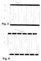
- Figure 3 shows a plan view of a further embodiment of the composite 1 of the present invention.
- a plurality of tape-shaped coated conductor 2 is arranged side by side and in parallel onto an electrically insulating support 3.
- Electrically contacts 4 are provided on each end of the coated conductor tapes 2, wherein the electrical contact 4 extends over all the ends of each side of all coated conductor tapes 2 for connecting the individual coated conductor tapes 2 electrically in parallel.
- FIG 4 a plan view of a composite 1 is shown having the same arrangement of coated conductor tapes 2 onto an insulating support 3 as in figure 3 .
- the individual coated conductor tapes 2 are connected electrically in series.
- the electrical contacts 4 are alternately connected to adjacent ends of adjacent coated conductor tapes 2 to form a meander.
- the free end of a single coated conductor tape 2 is provided with a further electrical contact for connecting the composite with the surrounding.
- the overall composite can have a cylinder shape as shown in figure 4 with electrical contacts 4 at the upper and lower end of the cylinder.
- the coated conductor tapes can be provided either onto the outer or inner surface or onto both surfaces of the cylinder.
- the tape-shaped coated conductors can be vertically or horizontally arranged. It is also possible to arrange the tape-shaped coated conductors within the cylindrical insulating material; i.e. embedding therein.
- Such a configuration of the composite 1 of the present invention can be suitably used as a component for a fault current limiter.
- the cold bore of the cryostat of a superconductor fault current limiter has also a cylinder form the configuration of the composite of figure 5 can be easily mounted within the cryostat.
- Two or more of such cylindrical composites can be mounted within the cryostat.
- a coaxial arrangement is possible with cylindrical composites of decreasing diameter.
- FIG. 6 A further configuration of the composite 1 of the present invention is shown in figure 6 . Shown is a composite 1 with disc shaped insulating support 3 and a plurality of coated conductor tapes 2 arranged in parallel and side by side onto a plan face of the disc-shaped insulating support 2.
- the disc shaped composite 1 can be placed into the cold bore of a cryostat 6.
- the round disc shaped composite 1 can be easily mounted within the interior of the cryostat 6 having typically also a round cross-sectional area.
- the plurality of coated conductor tapes 2 is connected electrically in parallel via the electrical contacts 4 provided at each end side of the coated conductor tapes 2 and covering all ends of the coated conductor tapes 2 at the respective side.
- the electrical contacts 4 are each connected to an electrical connection 5 for electrically connecting the coated conductor tapes 2 onto the composite 1 with the surrounding.
- the composite 1 can be electrically connected to further composites 1 additionally mounted within the cryostat.
- FIG. 7 A longitudinal section through an arrangement of a plurality of composites 1 arranged within a cryostat 6 is schematically shown in figure 7 .
- a plurality of composite plates 1 is mounted within a cryostat 6 one above the other to form a stack of composite plates 1.
- Reduction of inductance is possible by providing a configuration which allows changing direction of the current flow.
- An example for such a configuration is that shown in figure 4 wherein direction of current flow in adjacent coated conductors 2 is opposite to each other.
- the composites 2 can be connected electrically in series to enhance the length of current path available; they can be connected electrically in parallel for increasing the available current carrying cross section for allowing a higher nominal current. Also a combination of parallel and serial electrical connection is possible.
- one or more coated conductor tapes 2 can be arranged onto at least one surface of the support 3.
- coated conductor tapes 2 arranged onto at least one surface of a support 3 can be electrically connected in parallel and/or in series.
- the coated conductor tapes 2, arranged onto a surface of a support 3, are arranged side by side and in parallel.
- an adhesion promoter serves for compensating different thermal expansion of the electrically insulating material 3 and the coated conductor 2.
- the composite 1 of the present invention can be suitably used as a pre-fabricated module for superconducting applications and allows a high degree of standardisized production as well as modular configuration of the composites. By varying the number of composites and/or number of coated conductors of an individual composite 1 easy scaling up or down is possible. Moreover, the modular and standardized design of the composites of the present invention allows a compact and space saving layout within a container with only limited space such as in a cryostat.
- the composites of the present invention can be suitably used as prefabricated modular components such as a switching module for a fault current limiter, in particular a resistive fault current limiter.
- the composites can be easily mounted within a cryostat of a fault current limiter and allows simple adaption of a fault current limiter to the nominal current and nominal voltage level of the specific electrical application, for example power network which should be protected by the fault current limiter against high-fault currents.
Landscapes
- Superconductors And Manufacturing Methods Therefor (AREA)
- Containers, Films, And Cooling For Superconductive Devices (AREA)
- Emergency Protection Circuit Devices (AREA)
Priority Applications (4)
| Application Number | Priority Date | Filing Date | Title |
|---|---|---|---|
| EP11305136A EP2487731A1 (fr) | 2011-02-10 | 2011-02-10 | Composite doté d'un conducteur revêtu |
| US13/350,929 US20120208702A1 (en) | 2011-02-10 | 2012-01-16 | Composite with coated conductor |
| US13/358,754 US8425265B2 (en) | 2011-02-08 | 2012-01-26 | Arrangement with a clamp of metal constructed as a pipe piece |
| KR1020120013653A KR20120092077A (ko) | 2011-02-10 | 2012-02-10 | 코팅 도전체를 가진 복합체 |
Applications Claiming Priority (1)
| Application Number | Priority Date | Filing Date | Title |
|---|---|---|---|
| EP11305136A EP2487731A1 (fr) | 2011-02-10 | 2011-02-10 | Composite doté d'un conducteur revêtu |
Publications (1)
| Publication Number | Publication Date |
|---|---|
| EP2487731A1 true EP2487731A1 (fr) | 2012-08-15 |
Family
ID=43901319
Family Applications (1)
| Application Number | Title | Priority Date | Filing Date |
|---|---|---|---|
| EP11305136A Withdrawn EP2487731A1 (fr) | 2011-02-08 | 2011-02-10 | Composite doté d'un conducteur revêtu |
Country Status (3)
| Country | Link |
|---|---|
| US (1) | US20120208702A1 (fr) |
| EP (1) | EP2487731A1 (fr) |
| KR (1) | KR20120092077A (fr) |
Families Citing this family (2)
| Publication number | Priority date | Publication date | Assignee | Title |
|---|---|---|---|---|
| CN114496461B (zh) * | 2022-04-15 | 2022-07-05 | 中国科学院合肥物质科学研究院 | 一种具有复合型高温超导电流引线的高温超导组件 |
| EP4369544A1 (fr) * | 2022-11-10 | 2024-05-15 | NeutronStar Systems UG | Faisceau supraconducteur |
Citations (8)
| Publication number | Priority date | Publication date | Assignee | Title |
|---|---|---|---|---|
| DE19832274A1 (de) * | 1998-07-17 | 2000-01-20 | Siemens Ag | Resistiver Kurzschlußstrombegrenzer mit einer Leiterbahnstruktur aus Hoch-T¶c¶-Supraleitermaterial sowie Verfahren zur Herstellung des Strombegrenzers |
| EP1063712A2 (fr) * | 1999-06-25 | 2000-12-27 | Abb Research Ltd. | Composite supraconducteur à haute température |
| WO2001056089A2 (fr) * | 2000-01-28 | 2001-08-02 | Siemens Aktiengesellschaft | Dispositif resistif de limitation de courant dote d'une matiere supraconductrice a point critique eleve |
| EP1220337A1 (fr) * | 2000-12-27 | 2002-07-03 | Abb Research Ltd. | Limiteur de courant à supraconducteur |
| US20050139380A1 (en) * | 2003-12-31 | 2005-06-30 | Superpower, Inc. | Novel superconducting articles, and methods for forming and using same |
| US20070111893A1 (en) * | 2005-07-29 | 2007-05-17 | American Superconductor Corporation | High temperature superconducting wires and coils |
| WO2008079443A2 (fr) * | 2006-07-14 | 2008-07-03 | Superpower, Inc. | Procédé de formation d'un conducteur multifilament tolérant le courant alternatif avec élément de stabilisation strié, articles associés à ce conducteur et dispositif comprenant ce conducteur |
| US20080194411A1 (en) * | 2007-02-09 | 2008-08-14 | Folts Douglas C | HTS Wire |
-
2011
- 2011-02-10 EP EP11305136A patent/EP2487731A1/fr not_active Withdrawn
-
2012
- 2012-01-16 US US13/350,929 patent/US20120208702A1/en not_active Abandoned
- 2012-02-10 KR KR1020120013653A patent/KR20120092077A/ko not_active Withdrawn
Patent Citations (8)
| Publication number | Priority date | Publication date | Assignee | Title |
|---|---|---|---|---|
| DE19832274A1 (de) * | 1998-07-17 | 2000-01-20 | Siemens Ag | Resistiver Kurzschlußstrombegrenzer mit einer Leiterbahnstruktur aus Hoch-T¶c¶-Supraleitermaterial sowie Verfahren zur Herstellung des Strombegrenzers |
| EP1063712A2 (fr) * | 1999-06-25 | 2000-12-27 | Abb Research Ltd. | Composite supraconducteur à haute température |
| WO2001056089A2 (fr) * | 2000-01-28 | 2001-08-02 | Siemens Aktiengesellschaft | Dispositif resistif de limitation de courant dote d'une matiere supraconductrice a point critique eleve |
| EP1220337A1 (fr) * | 2000-12-27 | 2002-07-03 | Abb Research Ltd. | Limiteur de courant à supraconducteur |
| US20050139380A1 (en) * | 2003-12-31 | 2005-06-30 | Superpower, Inc. | Novel superconducting articles, and methods for forming and using same |
| US20070111893A1 (en) * | 2005-07-29 | 2007-05-17 | American Superconductor Corporation | High temperature superconducting wires and coils |
| WO2008079443A2 (fr) * | 2006-07-14 | 2008-07-03 | Superpower, Inc. | Procédé de formation d'un conducteur multifilament tolérant le courant alternatif avec élément de stabilisation strié, articles associés à ce conducteur et dispositif comprenant ce conducteur |
| US20080194411A1 (en) * | 2007-02-09 | 2008-08-14 | Folts Douglas C | HTS Wire |
Also Published As
| Publication number | Publication date |
|---|---|
| US20120208702A1 (en) | 2012-08-16 |
| KR20120092077A (ko) | 2012-08-20 |
Similar Documents
| Publication | Publication Date | Title |
|---|---|---|
| KR102852874B1 (ko) | 나선형 홈, 스택된 플레이트, 비절연 초전도 자석을 위한 전도체 및 냉각제 스킴 | |
| KR100669214B1 (ko) | 초전도체 물품 및 초전도체 코일 | |
| EP1691381B1 (fr) | Bobine supraconductrice limitant le courant de défaut | |
| US11488747B2 (en) | Superconducting power cable system | |
| US5235309A (en) | Resistive current limiter | |
| US20080070788A1 (en) | Resistive Type Super Conductive Current-Limiting Device Comprising a Strip-Shaped High-TC-Super Conductive Path | |
| US20080210454A1 (en) | Composite Superconductor Cable Produced by Transposing Planar Subconductors | |
| EP3298671B1 (fr) | Système de connexion pour systèmes supraconducteurs | |
| KR20150097509A (ko) | 코일 권선들 및 접촉부들을 포함하는 초전도 코일 장치 | |
| AU2019334792B2 (en) | Flexible HTS current leads | |
| JP2011040378A (ja) | 被覆導体 | |
| US20090156409A1 (en) | Fault current limiter incorporating a superconducting article | |
| EP2487731A1 (fr) | Composite doté d'un conducteur revêtu | |
| US20130040820A1 (en) | Fault current limiter incorporating a superconducting article and a heat sink | |
| US8260387B2 (en) | Superconducting articles and methods of fabrication thereof with reduced AC magnetic field losses | |
| JP7343859B2 (ja) | 伝導冷却型超伝導コイル | |
| JP5925827B2 (ja) | 超電導電流リード | |
| US8582256B2 (en) | Superconducting resistive fault current limiter | |
| JP2015035308A (ja) | 酸化物超電導線材の接続構造体、及びこれを備えた超電導機器 | |
| NZ550139A (en) | Composite superconductor cable produced by transposing planar subconductors |
Legal Events
| Date | Code | Title | Description |
|---|---|---|---|
| PUAI | Public reference made under article 153(3) epc to a published international application that has entered the european phase |
Free format text: ORIGINAL CODE: 0009012 |
|
| AK | Designated contracting states |
Kind code of ref document: A1 Designated state(s): AL AT BE BG CH CY CZ DE DK EE ES FI FR GB GR HR HU IE IS IT LI LT LU LV MC MK MT NL NO PL PT RO RS SE SI SK SM TR |
|
| AX | Request for extension of the european patent |
Extension state: BA ME |
|
| 17P | Request for examination filed |
Effective date: 20130215 |
|
| 17Q | First examination report despatched |
Effective date: 20130408 |
|
| RIC1 | Information provided on ipc code assigned before grant |
Ipc: H02H 9/02 20060101ALN20131031BHEP Ipc: H01L 39/16 20060101AFI20131031BHEP |
|
| GRAP | Despatch of communication of intention to grant a patent |
Free format text: ORIGINAL CODE: EPIDOSNIGR1 |
|
| INTG | Intention to grant announced |
Effective date: 20131210 |
|
| STAA | Information on the status of an ep patent application or granted ep patent |
Free format text: STATUS: THE APPLICATION IS DEEMED TO BE WITHDRAWN |
|
| 18D | Application deemed to be withdrawn |
Effective date: 20140423 |