EP2487775A1 - Mobiles endgerät sowie stromversorgungssystem, stromversorgungsverfahren und stromversorgungsprogramm für das mobile endgerät - Google Patents
Mobiles endgerät sowie stromversorgungssystem, stromversorgungsverfahren und stromversorgungsprogramm für das mobile endgerät Download PDFInfo
- Publication number
- EP2487775A1 EP2487775A1 EP10821876A EP10821876A EP2487775A1 EP 2487775 A1 EP2487775 A1 EP 2487775A1 EP 10821876 A EP10821876 A EP 10821876A EP 10821876 A EP10821876 A EP 10821876A EP 2487775 A1 EP2487775 A1 EP 2487775A1
- Authority
- EP
- European Patent Office
- Prior art keywords
- usb
- circuit
- power supply
- power
- portable terminal
- Prior art date
- Legal status (The legal status is an assumption and is not a legal conclusion. Google has not performed a legal analysis and makes no representation as to the accuracy of the status listed.)
- Withdrawn
Links
Images




Classifications
-
- G—PHYSICS
- G06—COMPUTING OR CALCULATING; COUNTING
- G06F—ELECTRIC DIGITAL DATA PROCESSING
- G06F1/00—Details not covered by groups G06F3/00 - G06F13/00 and G06F21/00
- G06F1/26—Power supply means, e.g. regulation thereof
- G06F1/263—Arrangements for using multiple switchable power supplies, e.g. battery and AC
-
- H—ELECTRICITY
- H01—ELECTRIC ELEMENTS
- H01M—PROCESSES OR MEANS, e.g. BATTERIES, FOR THE DIRECT CONVERSION OF CHEMICAL ENERGY INTO ELECTRICAL ENERGY
- H01M50/00—Constructional details or processes of manufacture of the non-active parts of electrochemical cells other than fuel cells, e.g. hybrid cells
- H01M50/20—Mountings; Secondary casings or frames; Racks, modules or packs; Suspension devices; Shock absorbers; Transport or carrying devices; Holders
- H01M50/269—Mechanical means for varying the arrangement of batteries or cells for different uses, e.g. for changing the number of batteries or for switching between series and parallel wiring
-
- H—ELECTRICITY
- H01—ELECTRIC ELEMENTS
- H01M—PROCESSES OR MEANS, e.g. BATTERIES, FOR THE DIRECT CONVERSION OF CHEMICAL ENERGY INTO ELECTRICAL ENERGY
- H01M50/00—Constructional details or processes of manufacture of the non-active parts of electrochemical cells other than fuel cells, e.g. hybrid cells
- H01M50/20—Mountings; Secondary casings or frames; Racks, modules or packs; Suspension devices; Shock absorbers; Transport or carrying devices; Holders
- H01M50/296—Mountings; Secondary casings or frames; Racks, modules or packs; Suspension devices; Shock absorbers; Transport or carrying devices; Holders characterised by terminals of battery packs
-
- H—ELECTRICITY
- H02—GENERATION; CONVERSION OR DISTRIBUTION OF ELECTRIC POWER
- H02J—ELECTRIC POWER NETWORKS; CIRCUIT ARRANGEMENTS OR SYSTEMS FOR SUPPLYING OR DISTRIBUTING ELECTRIC POWER; SYSTEMS FOR STORING ELECTRIC ENERGY
- H02J1/00—Circuit arrangements for DC mains or DC distribution networks
- H02J1/10—Parallel operation of DC sources
-
- H—ELECTRICITY
- H02—GENERATION; CONVERSION OR DISTRIBUTION OF ELECTRIC POWER
- H02J—ELECTRIC POWER NETWORKS; CIRCUIT ARRANGEMENTS OR SYSTEMS FOR SUPPLYING OR DISTRIBUTING ELECTRIC POWER; SYSTEMS FOR STORING ELECTRIC ENERGY
- H02J7/00—Circuit arrangements for charging or discharging batteries or for supplying loads from batteries
- H02J7/90—Regulation of charging or discharging current or voltage
- H02J7/94—Regulation of charging or discharging current or voltage in response to battery current
-
- H—ELECTRICITY
- H02—GENERATION; CONVERSION OR DISTRIBUTION OF ELECTRIC POWER
- H02J—ELECTRIC POWER NETWORKS; CIRCUIT ARRANGEMENTS OR SYSTEMS FOR SUPPLYING OR DISTRIBUTING ELECTRIC POWER; SYSTEMS FOR STORING ELECTRIC ENERGY
- H02J7/00—Circuit arrangements for charging or discharging batteries or for supplying loads from batteries
-
- Y—GENERAL TAGGING OF NEW TECHNOLOGICAL DEVELOPMENTS; GENERAL TAGGING OF CROSS-SECTIONAL TECHNOLOGIES SPANNING OVER SEVERAL SECTIONS OF THE IPC; TECHNICAL SUBJECTS COVERED BY FORMER USPC CROSS-REFERENCE ART COLLECTIONS [XRACs] AND DIGESTS
- Y02—TECHNOLOGIES OR APPLICATIONS FOR MITIGATION OR ADAPTATION AGAINST CLIMATE CHANGE
- Y02E—REDUCTION OF GREENHOUSE GAS [GHG] EMISSIONS, RELATED TO ENERGY GENERATION, TRANSMISSION OR DISTRIBUTION
- Y02E60/00—Enabling technologies; Technologies with a potential or indirect contribution to GHG emissions mitigation
- Y02E60/10—Energy storage using batteries
Definitions
- the present invention relates to portable terminal equipment, a power supply system, and a power supply method and a power supply program for portable terminal equipment; and in particular, relates to portable terminal equipment, a power supply system, and a power supply method and a power supply program for portable terminal equipment which receive power supply from host equipment.
- Portable terminal equipment described in patent documents 1, 3, 4 and 6 operates as follows. Host equipment and portable terminal equipment adjust current consumption for the portable terminal equipment according to a power supply capability of the host equipment or power consumption of the portable terminal equipment.
- Portable terminal equipment described in patent document 2 is a digital camera and operates as follows.
- the digital camera and a PC are connected via a USB (Universal Serial Bus) interface, amount of electric power which can be supplied from the PC is confirmed, and power is supplied from the PC based on the confirmation result.
- the digital camera supplies electricity to all or a part of function blocks which can be driven according to the amount of electric power which can be supplied. As a result, the supply power from the PC is utilized.
- Portable terminal equipment described in patent document 5 is a digital camera and operates as follows.
- the digital camera is divided into a first block which can operate by power supply from a USB interface and a second block which cannot operate by power supply from the USB interface.
- the digital camera includes: a mode which operates by electric power supplied from a battery, a mode which operates only by electric power supplied from a USB cable USB power supply and a mode which charges the battery.
- a PC judges in which mode the digital camera is and controls supply of electric power to the digital camera.
- a power supply circuit described in patent document 7 includes a power supply, DC-DC converter and a capacitor and operates as follows. A plurality of capacitors inserted in an input unit of the DC-DC converter guards so that input voltage of the DC-DC converter will not be cut off in case there occurs transient power outage, and prevents influences to a load.
- Display equipment described in patent document 8 includes a hub port and a host power supply and operates as follows. Even if the power supply by a power supply unit in the display equipment is cut off, a USB device is made to operate by the host power supply which is provided through the hub port connected to the host.
- the present invention makes it an object to provide portable terminal equipment, a power supply system, and a power supply method and a power supply program for portable terminal equipment which solves the first, the second and the third problem mentioned above.
- Portable terminal equipment of the present invention includes: a plurality of circuits separated in direct current and a power supply switching switch which switches power supply to the plurality of circuits between power supply from a USB (Universal Serial Bus) and power supply from a battery for each of respective circuits included in the plurality of circuits.
- USB Universal Serial Bus
- a power supply system of the present invention includes portable terminal equipment according to the present invention, host equipment including a USB and a battery.
- a power supply method for portable terminal equipment of the present invention includes a power supply switching procedure which switches power supply to a plurality of circuits separated in direct current between power supply from a USB (Universal Serial Bus) and power supply from a battery for each off respective circuits included in the plurality of circuits.
- a power supply switching procedure which switches power supply to a plurality of circuits separated in direct current between power supply from a USB (Universal Serial Bus) and power supply from a battery for each off respective circuits included in the plurality of circuits.
- a power supply program for portable terminal equipment of the present invention makes a computer execute a power supply switching step which switches power supply to a plurality of circuits separated in direct current between power supply from a USB (Universal Serial Bus) and power supply from a battery for each of respective circuits included in the plurality of circuits.
- a USB Universal Serial Bus
- portable terminal equipment a power supply system, and a power supply method and a power supply program for portable terminal equipment which solve the first, the second and the third problem mentioned above can be provided.
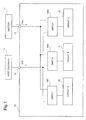
- a power supply system includes: portable terminal equipment 15 according to this exemplary embodiment, host equipment 10 including a USB and a battery 11.
- the portable terminal equipment 15 includes a VBUS terminal 16, and power supply from the USB of the host equipment 10 is made possible.
- the portable terminal equipment 15 includes a battery terminal 17, and power supply from the battery 11 is made possible.
- the portable terminal equipment 15 includes a circuit A 20, a circuit B 21, a circuit C 22, a power supply switching switch SW1, a power supply switching switch SW2 and a power supply switching switch SW3.
- the circuit A 20, the circuit B 21 and the circuit C 22 are, for example, the circuit A 20 of current consumption 100mA, the circuit B 21 of current consumption 400mA and the circuit C 22 of current consumption 400mA. Also, the circuit A 20, the circuit B 21 and the circuit C 22 are separated galvanically each other.
- the power supply switching switch SW1 switches power supply to the circuit A 20 between power supply from the USB included in the host equipment 10 and power supply from the battery 11.
- the power supply switching switch SW2 switches power supply to the circuit B 21 between power supply from the USB included in the host equipment 10 and power supply from the battery 11.
- the power supply switching switch SW3 switches power supply to the circuit C 22 between power supply from the USB included in the host equipment 10 and power supply from the battery 11.
- the power supply switching switches SW1, SW2 and SW3 select among the circuit A 20, the circuit B 21 and the circuit C 22 a circuit operable by electric power which the USB included in the host equipment 10 can supply.
- the power supply switching switches SW1, SW2 and SW3 may acquire information of the electric power which the USB included in the host equipment 10 can supply.
- the power supply switching switches SW1, SW2 and SW3 supply power from the USB to a circuit which the portable terminal equipment 15 selected and supply power from the battery 11 to a circuit which it did not select.
- the power supply switching switches SW1, SW2 and SW3 may select a circuit operable by electric power which the USB included in the host equipment 10 can supply among the circuit A 20, the circuit B 21 and the circuit C 22 based on specifications of the USB.
- the specifications of USB means, for example, whether the transfer rate of the USB is of Super Speed specifications, of High Speed specifications or of other specifications.
- the portable terminal equipment according to this exemplary embodiment may execute a power supply method for portable terminal equipment according to this exemplary embodiment.
- An example of a power supply method for portable terminal equipment according to this exemplary embodiment is shown in Fig. 2 .
- the power supply method for portable terminal equipment according to this exemplary embodiment includes a power supply switching procedure S111.
- power supply for the circuit A 20, the circuit B 21 and the circuit C 22 separated galvanically each other is switched between power supply from the USB included in the host equipment 10 and power supply from the battery 11 for each of the circuit A 20, the circuit B 21 and the circuit C 22.
- the portable terminal equipment 15 acquires information of electric power which the USB can supply, and selects a circuit operable by the electric power which the USB can supply among the circuit A 20, the circuit B 21 and the circuit C 22 based on the information. For example, the portable terminal equipment 15 acquires information of the electric power which can be supplied from the USB, supplies power from the USB to a circuit which is selected, and supplies power from the battery 11 to a circuit which is not selected. For example, in case the USB can supply the electric power with electric current of 100mA, the circuit A 20 is selected. And, power is supplied to the circuit A 20 from the USB, and power is supplied to the circuit B 21 and the circuit C 22 from the battery 11.
- either of the circuit B 21 and the circuit C 22 is selected. And, power is supplied to either of the circuit B 21 and the circuit C 22 from the USB, and power is supplied to the other and the circuit A 20 from the battery 11.
- Selection of a circuit among a plurality of circuits for which the electric power supply from the USB is possible can be performed, for example, as follows.
- the power supply switching switch acquires information of a transfer rate of the USB and information of the electric power which can be supplied from the USB, and determines whether the transfer rate of the USB is of Super Speed specifications. And, in case determined to be of the Super Speed specifications, whether the electric power which can be supplied from the USB is no smaller than 900mA of current consumption is determined. And, in case determined that the electric power which the USB can supply is no smaller than 900mA of current consumption, the circuit A of 100mA, the circuit B of 400mA and the circuit C of 400mA are selected.
- the portable terminal equipment 15 When connected by the USB, the portable terminal equipment 15 receives from the host equipment 10 only the electric power which can be received from the host equipment 10 and reduces consumption of the electric power from the battery 11 for that amount. As a result, it becomes possible to operate the portable terminal equipment 15 for a long time, and the problems are solved.
- the circuit A 20, the circuit B 21 and the circuit C 22 receiving electric power from the host equipment 10 may suspend receiving it from the battery 11. Further, the portable terminal equipment 15 may cut off VBUS and the battery 11, and make the battery 11 not to be charged by the electric power from the VBUS. By doing so, control of the circuit can be simplified. Accordingly, because complicated charge control considering heat generation becomes unnecessary, the development man-hour of portable terminal equipment can be reduced.
- power supply of the circuit A 20, the circuit B 21 and the circuit C 22 may be separated by a circuit size adjusted to the USB specifications.
- a circuit size adjusted to the USB specifications As a result, it becomes possible to receive the electric power from the host equipment to the maximum in line with the standard of the connected USB. Accordingly, for example, in case electric current of 1A is needed on a side of the portable terminal equipment 15, electric power of the present USB standard cannot meet all the electric power of the terminal, as mentioned above, by separating power supply of the circuit A 20, the circuit B 21 and the circuit C 22, it becomes possible for a part of the circuits to receive the electric power from the host equipment.
- the portable terminal equipment according to this exemplary embodiment may execute a portable terminal program according to this exemplary embodiment.
- An example of a portable terminal program according to this exemplary embodiment is shown in Fig. 3 .
- the portable terminal program according to this exemplary embodiment includes a power supply switching step S211.
- power supply switching step S211 power supply for the circuit A 20, the circuit B 21 and the circuit C 22 separated galvanically is switched between power supply from the USB included in the host equipment 10 and power supply from the battery 11 for each of the circuit A 20, the circuit B 21 and the circuit C 22.
- the power supply switching step S211 information of electric power which the USB can supply is acquired, and a circuit operable by the electric power which the USB can supply is selected among the circuit A 20, the circuit B 21 and the circuit C 22. And, power is supplied from the USB to the circuit which is selected, and power is supplied from the battery 11 to a circuit which is not selected.
- the portable terminal equipment according to this exemplary embodiment can be realized.
- the portable terminal equipment may be configured to include: a plurality of circuits separated galvanically; and a power supply switching switch which switches power supply to the plurality of circuits between power supply from the USB (Universal Serial Bus) and power supply from the battery for each of the respective circuits included in the plurality of circuits.
- a power supply switching switch which switches power supply to the plurality of circuits between power supply from the USB (Universal Serial Bus) and power supply from the battery for each of the respective circuits included in the plurality of circuits.
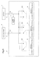
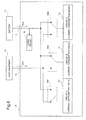
- a first example, a second example and a third example of the portable terminal equipment according to this exemplary embodiment are shown in Fig. 4 , Fig. 5 and Fig. 6 respectively.
- the first example, the second example and the third example of the portable terminal equipment are only different in the connection of the power supply switching switches SW1, SW2 and SW3, and their structures are the same.
- the first example of the portable terminal equipment indicates a case in which supply power of the USB corresponds to 900mA of current consumption.
- the second example of the portable terminal equipment indicates a case in which supply power of the USB corresponds to 500mA of current consumption.
- the third example of the portable terminal equipment indicates a case in which supply power of the USB corresponds to 100mA of current consumption.
- the portable terminal equipment 15 includes: a VBUS terminal 16 which can receive electric power from the USB included in the host equipment 10, a battery terminal 17 which can receive electric power from the battery 11, the circuit A 20 of which power supply is separated, and power consumption of 100mA of current consumption, the circuit B 21 of which power supply is separated, power consumption of 400mA of current consumption and the circuit C 22 of which power supply is separated, power consumption of 400mA of current consumption. Further, the portable terminal equipment 15 includes: the power supply switching switches SW1, SW2 and SW3 which can select an electric power receiving source of these circuits; and in addition, other circuit 14 which realizes other functions of the portable terminal equipment.
- the host equipment 10 is a computer such as a PC which becomes a power supply source of the portable terminal equipment 15.
- a computer such as a PC which becomes a power supply source of the portable terminal equipment 15.
- circuit 14 although there exist many parts such as CPU, a liquid crystal, a camera and a keyboard of which the portable terminal equipment 15 is composed, their details are omitted.
- the power supply switching switch SW1 selects whether to receive power supply of the circuit A 20 from the host equipment 10, or to receive it from the battery 11.
- the power supply switching switch SW2 selects whether to receive power supply of the circuit B 21 from the host equipment 10 or to receive it from the battery 11.
- the power supply switching switch SW3 selects whether to receive power supply of the circuit C 22 from the host equipment 10, or to receive it from the battery 11.
- the portable terminal equipment 15 receives electric current Ibat from the battery 11 connected to the battery terminal 17 and operates.
- the electric current Ibat flows to the power supply switching switch SW1 for the circuit A 20, the power supply switching switch SW2 for the circuit B 21, the power supply switching switch SW3 for the circuit C 22 and other circuit 14. Also, in case the portable terminal equipment 15 and the host equipment 10 are connected via the USB, the portable terminal equipment 15 can receive electric current Iusb from the VBUS terminal 16. The electric current Iusb flows to the power supply switching switch SW1 for the circuit A 20, the power supply switching switch SW2 for the circuit B 21, and the power supply switching switch SW3 for the circuit C 22.
- the portable terminal equipment 15 receives the electric power according to an ability of the host equipment 10. As a result, by the portable terminal equipment 15, it becomes possible to make duration for use of contents during USB connection longer.
- a method is generally known to assign the received electric power from the VBUS to charging of the battery 11 during USB connection, possibilities such as: charge control becomes complicated, and depending on a balance of received electric power from the VBUS and power consumption on the system side, charging becomes insufficient or heat is generated, are considered.
- there exist characteristics that such restrictions about charging can be evaded, and electric power can be received from the USB efficiently.
- FIG. 7 An exemplary configuration of the power supply switching switch will be described using Fig. 7 . Because the structure of the power supply switching switch SW2 and the power supply switching switch SW3 are same as the power supply switching switch SW1, their details are omitted.
- the power supply switching switch SW1 includes a switch for USB 30 and a switch for battery 31.
- the switch for USB 30 is connected in series between the VBUS terminal 16 and the circuit A 20. Also, the switch for USB 30 is turned to OFF state when electric potential when electric current is received from the USB is at Low electric potential, and suspends receiving of electric current Iusb1 from the USB by the circuit. On the other hand, when electric potential when electric current is received from the USB is not at Low electric potential, the switch for USB 30 will be turned to ON state, and electric current Iusb1 is received from the USB by the circuit.
- the switch for battery 31 is connected in series between the battery terminal 17 and the circuit A 20.
- the switch for battery 31 is turned to OFF state when the switch for USB 30 is at an ON state, and suspends receiving of electric current Ibat1 from the battery by the circuit.
- the switch for USB 30 is at OFF state, the switch for battery 31 will be turned to ON state and supplies electric current Ibat1 from the battery 11 to the circuit A 20.
- FET Field-Effect Transistor
- Voltage information detected by the voltage detection circuit 35 is sent to the current control circuit 36 and is converted into electric current.
- the current control circuit 36 adjusts ON resistance of the switch for USB 30 so that no smaller than 100mA of electric current does not flow.
- the switch for USB 30 is controlled to be turned to OFF state by the current control circuit 36.
- the switch for battery 31 As a circuit on the battery side, there exists the switch for battery 31 as a switch which decides whether the electric current Ibat1 received from the battery terminal 17 is made to flow to the circuit A 20.
- the switch for battery 31 is controlled directly by the voltage which is applied to the VBUS terminal 16.
- the VBUS terminal 16 is connected to the switch for battery 31 via a switch 38.
- the switch 38 is turned ON/OFF by a switch control circuit 37. Considering a time when the switch 38 becomes Open, it is necessary for a gate terminal of the switch for battery 31 to be pulled down by a resistance 39.
- a capacitor for anti-transient power outage 34 is installed.
- the capacitor for anti-transient power outage 34 even at the time the USB cable is disconnected, it is structured such that Isys1 which flows to the circuit A 20 can continue to be maintained.
- a procedure S2 is executed.
- information of a transfer rate of the USB and information of electric power which can be supplied from the USB are acquired.
- USB enumeration is started.
- the portable terminal equipment 15 can learn: whether the connection with the host equipment 10 is of Super Speed specifications as defined by USB3.0 standard, of High Speed specifications as defined by USB 2.0 standard, or of Full Speed specifications; and also at how many mA of electric current electric power can be received from the host equipment 10.
- a procedure S3 is executed. In the procedure S3, it is determined whether the transfer rate of the USB is of the Super Speed specifications.
- a procedure S4 is executed.
- a procedure J1 is executed. In the procedure J1, all of the power supply switching switch SW1, the power supply switching switch SW2 and the power supply switching switch SW3 are turned to the VBUS terminal 16 side.
- a procedure S5 is executed in case the transfer rate of the USB is not of the Super Speed specifications.
- a procedure S6 is executed in case it is of the High Speed specifications.
- a procedure S6 is executed in case it is distinguished whether electric power can be received from the host equipment 10 with electric current of 500mA.
- a procedure J2 is executed in case electric power can be received with electric current of 500mA.
- the power supply switching switch SW1 and the power supply switching switch SW2 are turned to the VBUS terminal 16 side.
- a procedure J3 is executed.
- the portable terminal equipment 15 can receive from the host equipment 10 only 100mA. Therefore, in the procedure J3, only the power supply switching switch Sow1 is turned to the VBUS terminal 16 side.
- Iusb1 indicates time series variation of ON resistance of the switch for battery, (d) indicates time series variation of electric current Ibat1, and (e) indicates time series variation of electric current Isys1, when a USB cable is pulled out.
- USB supports plug and play a cable may be pulled out at timing when the portable terminal equipment 15 does not intend.
- receiving of electric power from the VBUS is terminated, it becomes necessary to change power supply of all circuits such as the circuit A 20 which received electric power from the VBUS to the battery 11 from the VBUS.
- Fig. 9 (a) When the USB cable is pulled out, as shown in Fig. 9 (a) , voltage 50 applied at the VBUS terminal falls from 5V to 0V. Together with this, as shown in Fig. 9 (b) , electric current Iusb1 also falls to 0A.
- gate voltage of the switch for battery 31 is being controlled by the voltage of the VBUS.
- ON resistance 52 of the switch for battery 31 becomes small.
- ON state means that it is in full pass state. For this reason, the switch for battery 31 will become ON state.
- the portable terminal equipment can switch power supply from the VBUS to the battery at the same time as the USB is cut off. As a result, it is also possible to correspond to plug and play.
- a first effect by the portable terminal equipment according to this exemplary embodiment is: when being used in a state that the portable terminal equipment 15 and the host equipment 10 are connected, by receiving electric power only as much as receivable from the VBUS, a continuous use time of contents during USB connection can be extended.
- a second effect is: compared with USB charging, with an easy structure of software and hardware, it becomes possible to receive electric power from the USB.
- a third effect is: even when received electric power from the USB falls below the whole power consumption of the portable terminal equipment 15, it is possible to receive electric power of the USB efficiently.
- the present invention can be applied to portable terminal equipment with a USB port such as a portable computer, a PDA (Personal Digital Assistant), a portable Book terminal and a mobile phone, it can be utilized in an information and communications industry.
Landscapes
- Engineering & Computer Science (AREA)
- Power Engineering (AREA)
- Chemical & Material Sciences (AREA)
- Chemical Kinetics & Catalysis (AREA)
- Electrochemistry (AREA)
- General Chemical & Material Sciences (AREA)
- Theoretical Computer Science (AREA)
- Physics & Mathematics (AREA)
- General Engineering & Computer Science (AREA)
- General Physics & Mathematics (AREA)
- Power Sources (AREA)
- Charge And Discharge Circuits For Batteries Or The Like (AREA)
Applications Claiming Priority (2)
| Application Number | Priority Date | Filing Date | Title |
|---|---|---|---|
| JP2009234112 | 2009-10-08 | ||
| PCT/JP2010/066630 WO2011043205A1 (ja) | 2009-10-08 | 2010-09-17 | 携帯端末機器及び電源供給システム並びに携帯端末機器への電源供給方法及び電源供給プログラム |
Publications (2)
| Publication Number | Publication Date |
|---|---|
| EP2487775A1 true EP2487775A1 (de) | 2012-08-15 |
| EP2487775A4 EP2487775A4 (de) | 2014-04-16 |
Family
ID=43856668
Family Applications (1)
| Application Number | Title | Priority Date | Filing Date |
|---|---|---|---|
| EP10821876.9A Withdrawn EP2487775A4 (de) | 2009-10-08 | 2010-09-17 | Mobiles endgerät sowie stromversorgungssystem, stromversorgungsverfahren und stromversorgungsprogramm für das mobile endgerät |
Country Status (5)
| Country | Link |
|---|---|
| US (1) | US20120198250A1 (de) |
| EP (1) | EP2487775A4 (de) |
| JP (1) | JP5661041B2 (de) |
| CN (1) | CN102577021B (de) |
| WO (1) | WO2011043205A1 (de) |
Cited By (1)
| Publication number | Priority date | Publication date | Assignee | Title |
|---|---|---|---|---|
| CN104810040A (zh) * | 2015-03-30 | 2015-07-29 | 丰岛电子科技(苏州)有限公司 | 移动存储装置及充电方法 |
Families Citing this family (10)
| Publication number | Priority date | Publication date | Assignee | Title |
|---|---|---|---|---|
| JP5604134B2 (ja) * | 2010-02-24 | 2014-10-08 | 京セラ株式会社 | 携帯電子機器及び機器システム |
| JP2013090006A (ja) * | 2011-10-13 | 2013-05-13 | Nikon Corp | 電子機器およびプログラム |
| US8990592B2 (en) * | 2012-01-25 | 2015-03-24 | Smsc Holdings S.A.R.L. | Overcoming limited common-mode range for USB systems |
| TWI613546B (zh) * | 2013-03-28 | 2018-02-01 | 威盛電子股份有限公司 | 通用序列匯流排集線器及其控制方法 |
| US10216253B2 (en) | 2013-03-28 | 2019-02-26 | Via Technologies, Inc. | Universal serial bus hub and control method thereof |
| CN104951416A (zh) * | 2014-03-25 | 2015-09-30 | 瑞昱半导体股份有限公司 | 通用串行总线集线器、其控制模块以及其控制方法 |
| TWI705374B (zh) * | 2017-01-23 | 2020-09-21 | 威鋒電子股份有限公司 | 電子裝置及其操作方法 |
| US10852799B2 (en) * | 2017-07-14 | 2020-12-01 | Analog Devices Global Unlimited Company | Adaptive use of multiple power supplies in communication systems |
| US11164784B2 (en) | 2019-08-22 | 2021-11-02 | Micron Technology, Inc. | Open-drain transistor monitoring circuit in a multi-chip package to control power |
| US11237612B2 (en) | 2019-08-22 | 2022-02-01 | Micron Technology, Inc. | Charge-sharing capacitive monitoring circuit in a multi-chip package to control power |
Family Cites Families (22)
| Publication number | Priority date | Publication date | Assignee | Title |
|---|---|---|---|---|
| JPH0630524A (ja) | 1992-07-09 | 1994-02-04 | Fujitsu Ltd | 電源回路 |
| KR100193737B1 (ko) | 1996-07-19 | 1999-06-15 | 윤종용 | 디스플레이 장치 및 그의 전원공급제어방법 |
| KR100315679B1 (ko) * | 1998-01-16 | 2002-02-28 | 윤종용 | 유에스비허브의전원회로 |
| JP3784589B2 (ja) | 1999-09-29 | 2006-06-14 | コニカミノルタフォトイメージング株式会社 | 携帯機器 |
| JP3674855B2 (ja) * | 2002-03-20 | 2005-07-27 | ソニー株式会社 | 電源制御装置および電源制御方法 |
| JP3935011B2 (ja) | 2002-07-17 | 2007-06-20 | 株式会社アイ・オー・データ機器 | 情報伝達ケーブル |
| TWM248624U (en) * | 2002-10-28 | 2004-11-01 | Walton Advanced Eng Inc | Pen featuring with memory function |
| US20050033996A1 (en) | 2002-11-15 | 2005-02-10 | Piau Fong | Method and apparatus for a communication hub |
| US20040158360A1 (en) * | 2003-02-04 | 2004-08-12 | Charles Garland | System and method of energy management and allocation within an energy grid |
| WO2005015366A2 (en) * | 2003-08-08 | 2005-02-17 | Electric Power Group, Llc | Real-time performance monitoring and management system |
| JP4502360B2 (ja) * | 2003-08-27 | 2010-07-14 | キヤノン株式会社 | 撮像装置 |
| WO2005024613A1 (ja) | 2003-08-28 | 2005-03-17 | Fujitsu Limited | ホスト装置、デバイス、及び通信システムの制御方法 |
| JP2005078475A (ja) * | 2003-09-02 | 2005-03-24 | Fuji Photo Film Co Ltd | データ転送装置 |
| US7329969B2 (en) * | 2003-10-15 | 2008-02-12 | Teac Corporation | Electronic device including interface terminal and power supply cable connected thereto |
| JP2005173822A (ja) | 2003-12-09 | 2005-06-30 | Canon Inc | 情報処理方法、情報処理システム、プログラム及び記憶媒体 |
| WO2006080957A2 (en) * | 2004-09-30 | 2006-08-03 | Vector Products, Inc. | Portable accessory device having a port interface used to provide multiple integrated functionalities |
| JP2006262610A (ja) * | 2005-03-16 | 2006-09-28 | Mitsumi Electric Co Ltd | 電源回路 |
| JP2007068282A (ja) * | 2005-08-30 | 2007-03-15 | Freescale Semiconductor Inc | 電源回路 |
| WO2008030398A2 (en) * | 2006-09-05 | 2008-03-13 | Summit Microelectronics, Inc | Circuits and methods for controlling power in a battery operated system |
| US20090063257A1 (en) * | 2007-08-31 | 2009-03-05 | Powerit Solutions, Llc | Automated peak demand controller |
| JP5162188B2 (ja) | 2007-08-31 | 2013-03-13 | 京セラ株式会社 | 携帯通信端末、起動方法およびブートプログラム |
| JP4572243B2 (ja) | 2008-03-27 | 2010-11-04 | 信越化学工業株式会社 | 熱伝導性積層体およびその製造方法 |
-
2010
- 2010-09-17 JP JP2011535347A patent/JP5661041B2/ja not_active Expired - Fee Related
- 2010-09-17 US US13/500,141 patent/US20120198250A1/en not_active Abandoned
- 2010-09-17 WO PCT/JP2010/066630 patent/WO2011043205A1/ja not_active Ceased
- 2010-09-17 CN CN201080045609.0A patent/CN102577021B/zh not_active Expired - Fee Related
- 2010-09-17 EP EP10821876.9A patent/EP2487775A4/de not_active Withdrawn
Cited By (1)
| Publication number | Priority date | Publication date | Assignee | Title |
|---|---|---|---|---|
| CN104810040A (zh) * | 2015-03-30 | 2015-07-29 | 丰岛电子科技(苏州)有限公司 | 移动存储装置及充电方法 |
Also Published As
| Publication number | Publication date |
|---|---|
| JP5661041B2 (ja) | 2015-01-28 |
| US20120198250A1 (en) | 2012-08-02 |
| EP2487775A4 (de) | 2014-04-16 |
| CN102577021B (zh) | 2015-01-21 |
| JPWO2011043205A1 (ja) | 2013-03-04 |
| WO2011043205A1 (ja) | 2011-04-14 |
| CN102577021A (zh) | 2012-07-11 |
Similar Documents
| Publication | Publication Date | Title |
|---|---|---|
| US20120198250A1 (en) | Portable terminal equipment, a power supply system, and a power supply method and a power supply program for portable terminal equipment | |
| CN103107569B (zh) | 执行系统电源管理的方法及装置 | |
| KR101504104B1 (ko) | 역 로컬 데이터 전송 접속을 통하여 전력을 제공하는 시스템 및 방법 | |
| CN101728859B (zh) | 移动终端间电池共享的系统、方法及移动终端 | |
| CN103777730B (zh) | 电源管理电路及其方法 | |
| US20170126041A1 (en) | Charger circuit | |
| US8949631B2 (en) | USB power supply method and device, and end device and system using the same | |
| CN101415043B (zh) | 发觉外部装置的移动终端及其控制方法 | |
| CN107465227B (zh) | 一种电子设备及其控制方法 | |
| KR102052443B1 (ko) | 충전 및 데이터 통신을 수행할 수 있는 시스템 | |
| US20120194124A1 (en) | Wireless Battery Charging System | |
| KR20100072857A (ko) | 휴대 단말기의 인터럽트 제어 방법 및 제어 장치 | |
| CN108206444B (zh) | 数据线及数据传输方法 | |
| US20130049680A1 (en) | Electronic device | |
| EP3084557A1 (de) | Verfahren und vorrichtung zum laden einer elektronischen vorrichtung mit usb-anschluss | |
| CN101261533A (zh) | 计算机及其电池充电方法 | |
| EP2755109A1 (de) | Laden einer elektrischen Vorrichtungen über eine Datenschnittstelle | |
| EP2784901B1 (de) | USB-Ladegeräte und Ladeverwaltungsverfahren | |
| CN106340780A (zh) | 终端设备及其控制方法 | |
| US9252618B2 (en) | Terminals, terminal systems and charging/discharging methods thereof | |
| CN113708459B (zh) | 充电电路和电子设备 | |
| US20100180132A1 (en) | Power Management Device for a Computer System and Related Power Management Method and Computer System | |
| WO2010067400A1 (ja) | 電力使用方法、スレーブ装置、およびコンピュータプログラム | |
| CN102768570A (zh) | 一种电子设备 | |
| US10459503B2 (en) | Electronic system, terminal device, and function expansion device |
Legal Events
| Date | Code | Title | Description |
|---|---|---|---|
| PUAI | Public reference made under article 153(3) epc to a published international application that has entered the european phase |
Free format text: ORIGINAL CODE: 0009012 |
|
| 17P | Request for examination filed |
Effective date: 20120330 |
|
| AK | Designated contracting states |
Kind code of ref document: A1 Designated state(s): AL AT BE BG CH CY CZ DE DK EE ES FI FR GB GR HR HU IE IS IT LI LT LU LV MC MK MT NL NO PL PT RO SE SI SK SM TR |
|
| DAX | Request for extension of the european patent (deleted) | ||
| A4 | Supplementary search report drawn up and despatched |
Effective date: 20140317 |
|
| RIC1 | Information provided on ipc code assigned before grant |
Ipc: H01M 10/44 20060101ALI20140311BHEP Ipc: G06F 1/26 20060101ALI20140311BHEP Ipc: H02J 1/10 20060101ALI20140311BHEP Ipc: H02J 7/34 20060101AFI20140311BHEP |
|
| STAA | Information on the status of an ep patent application or granted ep patent |
Free format text: STATUS: THE APPLICATION HAS BEEN WITHDRAWN |
|
| 18W | Application withdrawn |
Effective date: 20150310 |