EP2488718B1 - Dispositif de rentrée automatique et d'amortissement - Google Patents
Dispositif de rentrée automatique et d'amortissement Download PDFInfo
- Publication number
- EP2488718B1 EP2488718B1 EP10771689.6A EP10771689A EP2488718B1 EP 2488718 B1 EP2488718 B1 EP 2488718B1 EP 10771689 A EP10771689 A EP 10771689A EP 2488718 B1 EP2488718 B1 EP 2488718B1
- Authority
- EP
- European Patent Office
- Prior art keywords
- damper
- damping device
- driver
- spring element
- bar linkage
- Prior art date
- Legal status (The legal status is an assumption and is not a legal conclusion. Google has not performed a legal analysis and makes no representation as to the accuracy of the status listed.)
- Not-in-force
Links
- 238000013016 damping Methods 0.000 title claims description 46
- 230000009471 action Effects 0.000 claims description 10
- 230000002040 relaxant effect Effects 0.000 claims description 4
- 230000008878 coupling Effects 0.000 description 14
- 238000010168 coupling process Methods 0.000 description 14
- 238000005859 coupling reaction Methods 0.000 description 14
- 239000012190 activator Substances 0.000 description 7
- 238000006073 displacement reaction Methods 0.000 description 6
- 230000007246 mechanism Effects 0.000 description 6
- 238000010586 diagram Methods 0.000 description 5
- 230000001419 dependent effect Effects 0.000 description 2
- 230000005284 excitation Effects 0.000 description 2
- 238000000034 method Methods 0.000 description 2
- 230000008569 process Effects 0.000 description 2
- 230000008901 benefit Effects 0.000 description 1
- 238000010276 construction Methods 0.000 description 1
- 230000007423 decrease Effects 0.000 description 1
- 230000000694 effects Effects 0.000 description 1
- 239000012530 fluid Substances 0.000 description 1
- 238000009434 installation Methods 0.000 description 1
Images


Classifications
-
- E—FIXED CONSTRUCTIONS
- E05—LOCKS; KEYS; WINDOW OR DOOR FITTINGS; SAFES
- E05F—DEVICES FOR MOVING WINGS INTO OPEN OR CLOSED POSITION; CHECKS FOR WINGS; WING FITTINGS NOT OTHERWISE PROVIDED FOR, CONCERNED WITH THE FUNCTIONING OF THE WING
- E05F5/00—Braking devices, e.g. checks; Stops; Buffers
- E05F5/02—Braking devices, e.g. checks; Stops; Buffers specially for preventing the slamming of swinging wings during final closing movement, e.g. jamb stops
- E05F5/027—Braking devices, e.g. checks; Stops; Buffers specially for preventing the slamming of swinging wings during final closing movement, e.g. jamb stops with closing action
-
- E—FIXED CONSTRUCTIONS
- E05—LOCKS; KEYS; WINDOW OR DOOR FITTINGS; SAFES
- E05F—DEVICES FOR MOVING WINGS INTO OPEN OR CLOSED POSITION; CHECKS FOR WINGS; WING FITTINGS NOT OTHERWISE PROVIDED FOR, CONCERNED WITH THE FUNCTIONING OF THE WING
- E05F1/00—Closers or openers for wings, not otherwise provided for in this subclass
- E05F1/08—Closers or openers for wings, not otherwise provided for in this subclass spring-actuated, e.g. for horizontally sliding wings
- E05F1/16—Closers or openers for wings, not otherwise provided for in this subclass spring-actuated, e.g. for horizontally sliding wings for sliding wings
-
- E—FIXED CONSTRUCTIONS
- E05—LOCKS; KEYS; WINDOW OR DOOR FITTINGS; SAFES
- E05Y—INDEXING SCHEME ASSOCIATED WITH SUBCLASSES E05D AND E05F, RELATING TO CONSTRUCTION ELEMENTS, ELECTRIC CONTROL, POWER SUPPLY, POWER SIGNAL OR TRANSMISSION, USER INTERFACES, MOUNTING OR COUPLING, DETAILS, ACCESSORIES, AUXILIARY OPERATIONS NOT OTHERWISE PROVIDED FOR, APPLICATION THEREOF
- E05Y2201/00—Constructional elements; Accessories therefor
- E05Y2201/40—Motors; Magnets; Springs; Weights; Accessories therefor
- E05Y2201/47—Springs
- E05Y2201/488—Traction springs
-
- E—FIXED CONSTRUCTIONS
- E05—LOCKS; KEYS; WINDOW OR DOOR FITTINGS; SAFES
- E05Y—INDEXING SCHEME ASSOCIATED WITH SUBCLASSES E05D AND E05F, RELATING TO CONSTRUCTION ELEMENTS, ELECTRIC CONTROL, POWER SUPPLY, POWER SIGNAL OR TRANSMISSION, USER INTERFACES, MOUNTING OR COUPLING, DETAILS, ACCESSORIES, AUXILIARY OPERATIONS NOT OTHERWISE PROVIDED FOR, APPLICATION THEREOF
- E05Y2900/00—Application of doors, windows, wings or fittings thereof
- E05Y2900/20—Application of doors, windows, wings or fittings thereof for furniture, e.g. cabinets
Definitions
- the present invention relates to a Disposable furniture parts according to the preamble of claim 1.
- Object of the present invention is to provide adicauchs- and damping device for movable furniture parts, in which a self-closing and damping of the movement of the movable furniture part in the direction of movement of the furniture part are made possible.
- the driver which can be coupled with the movable furniture part, the damper, with the movement of the driver at least is braked in one direction and a spring element, by means of which a movement of the driver is accelerated from a first position to a second position, coupled via a straight guide of the driver causing four-bar linkage together.
- the four-bar linkage has two with a respective end to a furniture body rotatably fixable rockers and rotatably fixed to the other ends of the rocker coupling.
- the spring element is coupled to a first coupling point formed on the articulation point of the four-bar linkage, which undergoes a curve at a the spring element on or relaxing movement of the four-bar linkage.
- the damper is coupled to the four-bar linkage such that the effective direction of the damper counteracts the direction of action of the spring element, wherein the damper is coupled to a second provided on the coupling or the rocker articulation point.
- the damper is designed as a linear damper.
- a suitable choice of the attachment points of spring element and damper is on the one hand ensures that the direction of action of the spring element counteracts the direction of action of the damper, on the other hand, so the force-displacement curve can be adjusted as needed.
- the damper is designed as a rotary damper, in particular as an eddy current brake. This is the braking effect the damper to a fluid damper largely independent of temperature influences. Furthermore, an eddy current brake can be very compact
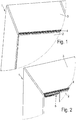
- the Figures 1 and 2 show a furniture body 1 with a, here designed as a sliding door movable furniture part 2.
- the movable furniture part 2 is provided on its the furniture body 1 side facing at least one fitting 12 (shown in FIG FIG. 5 ), on which a roller 11 is mounted, which is mounted in a mounted on a ceiling plate 3 of the furniture body guide rail 4 in a raceway 9, 10 of the guide rail 4 slidably.
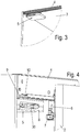
- FIG. 1 is the movable furniture part 2 in a closed position, in FIG. 2 in a partially open position, in which a variant of the Diseinzugs- and damping device 5 can be seen, which, as in the detailed representation in FIG. 3 shown, preferably fixed to the ceiling plate 3 of the furniture body 1.
- the Disclosed- and damping device 5 a housing 8, from which a driver 30 protrudes toward the movable furniture part 2 out, which is shaped so that it is fixed to the movable furniture part 2 activator 6 during movement of the movable furniture part 2 receives from a partially open position to a closed position and moves together with the movable furniture part 2 in a closed position.
- the activator 6 is preferably designed as a cylindrical rod which is mounted on a mounting platform 7, wherein the mounting platform 7 is in turn mounted on the fitting 12 on the movable furniture part 2.
- the driver 30 has a movable furniture part 2 toward approximately U-shaped opening 31 in which the activator 6 can be accommodated and the driver 30 so holds the activator 6 in the direction of movement of the movable furniture part 2.
- a tongue 32 for easier recording of the activator 6 is formed at one end of the U-shaped opening 31 of the driver 30, a tongue 32 to which the activator 6 abuts when entering the U-shaped opening 31.
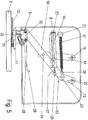
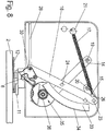
- the driver 30 is coupled to a housed in the housing 8 of Dieinzugs- and damping device 5 four-bar linkage 13.
- the four-bar linkage 13 consists of two with a respective end to the furniture body 1 rotatably fixed wings 14, 15 and at the other ends of the rockers 14, 15 rotatably fixed coupling 16. At the free end of the coupling 16 of the driver 30 is coupled.
- the four-bar linkage 13 is further coupled to a movement of the driver 30 from a first position to a second position in a direction accelerating spring element 17 and a damper 18, by means of which a movement of the driver 30 in the direction in which the spring force of Spring element 17 acts, is braked.
- the attachment points 19, 20, on which the wings 14,15 are fixed to the furniture body 1 and the coupling joints 23, 24 of the wings 14, 15 with the coupling 16 are designed so that the free end of the coupling 16, on which the driver 30 is coupled, a straight guide of the driver 30 along a rectilinear portion of a cam guide 28 acts.
- FIG. 5 shows the four-bar linkage 13 in a position in which the driver 30 is in a closed position
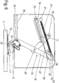
- FIG. 6 shows the four-bar linkage 13 in a position in which the driver 30 is in an open position in which the driver 30 is retracted into a curve piece 29 of the cam guide 28 and thereby the open end of the U-shaped opening 31 of the driver by an angle in Opening direction of the movable furniture part 2 is twisted.
- the rocker 15 is in dead center by the action line of the spring element 17 passes through the attachment point 20 of the rocker 15. This results in a restoring torque-free state, which can be used for latching the system, since the four-bar linkage 13 does not leave the reached position without external excitation.
- the damper 18 is designed as a linear damper.
- the rotatably mounted at one end to an attachment point 22 on the furniture body 1 damper 18 is coupled here at a pivot point 25 on the coupling 16, but may, for example, on the attachment point 22 of the damper 18 closer rocker 14.
- Trained as a linear damper damper 18 is formed here, for example, as a known from the prior art damper with a housing from which a damping ram 27 protrudes, which is preferably fixed with its pivot point 25 to the coupling 16 rotatable.
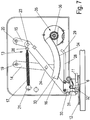
- the damper 35 is designed as a rotary damper, preferably as an eddy-current brake, as shown in FIGS FIGS. 7 and 8th is shown.
- the damping force of Dieinzugs- and damping device 5 and braking force of the eddy current brake 35 can be adjusted, for example, via the introduction of a different number of permanent magnets in a simple manner.
- a rack 33 is fixed to the rocker 14 of the four-bar mechanism 13, which is preferably shaped like a circle-shaped and is provided on its outside with teeth 34 which mesh with a ring gear 36 of the damper 35.
- the rack 33 is in this embodiment rigidly connected to the rocker 14. It is also conceivable, however, a one-piece design of rocker 14 and rack 33rd
- FIGS. 9 and 10 again show the embodiments of Diseinzugs- and damping device 5 in an exploded view, wherein FIG. 9 the embodiment with a trained as a linear damper damper 18 and FIG. 10 a variant with a designed as a rotary damper damper 35th
- FIGS. 11 and 12 is shown a comparison of a force-displacement diagram, wherein the FIG. 11 shows the force-displacement diagram of a self-closing and damping device according to the prior art, while the FIG. 12 a force-displacement diagram of a Deinyaks- and damping device according to the present invention shows.
- an increasing force must be applied during an opening operation of a movable furniture part with increasing distance traveled by the driver in order to counteract the spring force of the spring element 17.
- the spring element 17 is deflected by a large distance.
- the application of the Diseinzugs- and damping device according to the present invention is not limited to the use of a designed as a sliding door movable furniture part, but can for example be used in push elements or the like.
- a furniture equipped with such a Aseinzugs- and damping device the user is allowed to move a movable furniture part 2 of the furniture with little effort.
Landscapes
- Engineering & Computer Science (AREA)
- Mechanical Engineering (AREA)
- Civil Engineering (AREA)
- Structural Engineering (AREA)
- Vibration Dampers (AREA)
- Closing And Opening Devices For Wings, And Checks For Wings (AREA)
- Fluid-Damping Devices (AREA)
- Drawers Of Furniture (AREA)
Claims (8)
- Dispositif de rétraction automatique et d'amortissement (5) pour des parties de meuble mobiles (2), comprenant- un entraîneur (30) qui peut être couplé à une partie de meuble mobile (2),- un amortisseur (18, 35), au moyen duquel un mouvement de l'entraîneur (30) dans au moins un sens est freiné,- un élément de ressort (17) au moyen duquel un mouvement de l'entraîneur (30) entre une première position et une deuxième position est accéléré,caractérisé en ce que- l'amortisseur (18, 35), l'entraîneur (30)et l'élément de ressort (17) sont couplés les uns aux autres par un quadrilatère articulé (13) réalisant un guidage rectiligne de l'entraîneur (30),- le quadrilatère articulé (13) présentant deux bras oscillants (14, 15) qui peuvent être fixés avec possibilité de rotation sur un corps de meuble (1) à chaque extrémité et une bielle (16) fixée avec possibilité de rotation aux autres extrémités des bras oscillants (14, 15),- l'élément de ressort (17) étant couplé au quadrilatère articulé (13) en un premier point d'articulation (26) formé sur la bielle (16), qui parcourt une courbe lors d'un mouvement du quadrilatère articulé (13) tendant ou détendant l'élément de ressort (17),- l'amortisseur (18) étant couplé au quadrilatère articulé (13) de telle manière que le sens d'action de l'amortisseur (18) s'oppose au sens d'action de l'élément de ressort (17),- l'amortisseur (18) étant couplé en un deuxième point d'articulation (25) prévu sur la bielle (16) ou sur l'un des bras oscillants (14, 15)
et- l'amortisseur (18) étant conçu comme un amortisseur linéaire. - Dispositif de rétraction automatique et d'amortissement (5) selon le préambule de la revendication 1, caractérisé en ce que- l'amortisseur (35), l'entraîneur (30) et l'élément de ressort (17) sont couplés entre eux par un quadrilatère articulé (13) réalisant un guidage rectiligne de l'entraîneur (30),- lequel quadrilatère articulé (13) présente deux bras oscillants (14, 15) pouvant être fixés avec possibilité de rotation sur un corps de meuble (1) à chaque extrémité et une bielle (16) fixée aux autres extrémités des bras oscillants (14, 15) avec possibilité de rotation,- l'élément de ressort (17) étant couplé au quadrilatère articulé (13) en un premier point d'articulation (26) formé sur la bielle (16), qui parcourt une courbe lors d'un mouvement du quadrilatère articulé (13) tendant ou détendant l'élément de ressort (17),- l'amortisseur (35) étant couplé au quadrilatère articulé (13) de telle manière que le sens d'action de l'amortisseur (18) s'oppose au sens d'action de l'élément de ressort (17),- l'amortisseur (35) étant conformé comme un amortisseur rotatif,- l'amortisseur (35) étant couplé au quadrilatère articulé (13) par une crémaillère (33) fixée sur le quadrilatère articulé (13).
- Dispositif de rétraction automatique et d'amortissement (5) selon la revendication 2, caractérisé en ce que l'amortisseur (35) est conformé comme un ralentisseur à courants de Foucault.
- Dispositif de rétraction automatique et d'amortissement (5) selon la revendication 2, caractérisé en ce que la crémaillère (33) est fixée sur l'un des bras oscillants (14, 15).
- Dispositif de rétraction automatique et d'amortissement (5) selon l'une des revendications précédentes, caractérisé en ce que l'entraîneur (30) est mobile dans un rail de guidage (28) d'une position de départ, dans laquelle la partie de meuble (2) se trouve dans une position de fermeture, à une position de fin de course dans laquelle la partie de meuble (2) se trouve dans une position partiellement ouverte.
- Dispositif de rétraction automatique et d'amortissement (5) selon la revendication 4, caractérisé en ce que le guide en courbe (28) présente à une extrémité une partie incurvée (29) dans laquelle l'entraîneur (30) peut être basculé.
- Dispositif de rétraction automatique et d'amortissement (5) selon l'une des revendications précédentes, caractérisé en ce que la partie de meuble (2) est conçue comme une paroi d'armoire coulissante, un tiroir ou similaire.
- Meuble présentant un corps de meuble (1) et une partie de meuble (2) mobile par rapport à ce corps de meuble (1), caractérisé en ce qu'il comporte un dispositif de rétraction automatique et d'amortissement (5) selon l'une des revendications précédentes.
Priority Applications (1)
| Application Number | Priority Date | Filing Date | Title |
|---|---|---|---|
| PL10771689T PL2488718T3 (pl) | 2009-10-14 | 2010-10-07 | Urządzenie do samoczynnego dociągania i amortyzacji |
Applications Claiming Priority (2)
| Application Number | Priority Date | Filing Date | Title |
|---|---|---|---|
| DE200920013347 DE202009013347U1 (de) | 2009-10-14 | 2009-10-14 | Selbsteinzugs- und Dämpfungsvorrichtung |
| PCT/EP2010/065000 WO2011045226A1 (fr) | 2009-10-14 | 2010-10-07 | Dispositif de rentrée automatique et d'amortissement |
Publications (2)
| Publication Number | Publication Date |
|---|---|
| EP2488718A1 EP2488718A1 (fr) | 2012-08-22 |
| EP2488718B1 true EP2488718B1 (fr) | 2016-12-07 |
Family
ID=43413505
Family Applications (1)
| Application Number | Title | Priority Date | Filing Date |
|---|---|---|---|
| EP10771689.6A Not-in-force EP2488718B1 (fr) | 2009-10-14 | 2010-10-07 | Dispositif de rentrée automatique et d'amortissement |
Country Status (9)
| Country | Link |
|---|---|
| EP (1) | EP2488718B1 (fr) |
| JP (1) | JP5845512B2 (fr) |
| KR (1) | KR101743428B1 (fr) |
| CN (1) | CN102549227B (fr) |
| BR (1) | BR112012008547A2 (fr) |
| DE (1) | DE202009013347U1 (fr) |
| PL (1) | PL2488718T3 (fr) |
| RU (1) | RU2526775C2 (fr) |
| WO (1) | WO2011045226A1 (fr) |
Families Citing this family (10)
| Publication number | Priority date | Publication date | Assignee | Title |
|---|---|---|---|---|
| DE202013003188U1 (de) * | 2013-04-08 | 2014-07-10 | Grass Gmbh & Co. Kg | Vorrichtung zur Bewegungskontrolle eines Möbelteils und Möbel mit einer solchen Vorrichtung |
| ITMI20140344U1 (it) * | 2014-11-11 | 2016-05-11 | Bortoluzzi Sistemi Spa | Dispositivo di smorzamento o richiamo per ante scorrevoli |
| DE102015118961B4 (de) * | 2015-11-05 | 2022-03-03 | Assa Abloy Sicherheitstechnik Gmbh | Türantriebseinrichtung mit ein-/auskuppelbarem Gestänge |
| AT517591B1 (de) * | 2015-09-15 | 2017-03-15 | Blum Gmbh Julius | Stellantrieb für Möbelteile |
| DE102015118965B4 (de) * | 2015-11-05 | 2022-03-03 | Assa Abloy Sicherheitstechnik Gmbh | Türantriebseinrichtung mit ein-/auskuppelbarem Gestänge |
| CN108868421B (zh) * | 2018-09-06 | 2024-04-30 | 广东美的厨房电器制造有限公司 | 缓冲关门组件和烹饪设备 |
| CN113738209B (zh) * | 2020-05-29 | 2023-03-17 | 青岛海尔电冰箱有限公司 | 铰链结构 |
| CN113738208B (zh) * | 2020-05-29 | 2023-03-17 | 青岛海尔电冰箱有限公司 | 铰链结构 |
| CN113738206B (zh) * | 2020-05-29 | 2023-03-17 | 青岛海尔电冰箱有限公司 | 冰箱 |
| CN113738214B (zh) * | 2020-05-29 | 2023-04-18 | 青岛海尔电冰箱有限公司 | 铰链结构 |
Family Cites Families (15)
| Publication number | Priority date | Publication date | Assignee | Title |
|---|---|---|---|---|
| JPS6348872U (fr) * | 1986-09-19 | 1988-04-02 | ||
| CN2188123Y (zh) * | 1994-04-08 | 1995-01-25 | 潘元璋 | 可调式液压缓冲闭门器 |
| JP3976918B2 (ja) * | 1998-11-30 | 2007-09-19 | 美和ロック株式会社 | 引戸のクローザにおけるワイアのたるみ除去装置 |
| KR100383370B1 (ko) * | 1999-02-08 | 2003-05-12 | 카야바 고교 가부시기가이샤 | 캐스터 |
| JP2000320954A (ja) | 1999-05-11 | 2000-11-24 | Hoshizaki Electric Co Ltd | 貯蔵庫の扉構造 |
| JP4008158B2 (ja) * | 1999-07-09 | 2007-11-14 | 美和ロック株式会社 | 引戸の遅延装置 |
| AT410504B (de) * | 2000-01-14 | 2003-05-26 | Blum Gmbh Julius | Schliess- und/oder einzugsvorrichtung für bewegbare möbelteile |
| ITMC20030144A1 (it) * | 2003-12-05 | 2005-06-06 | Compagnucci Spa Ora Compagnucci Ho Lding Spa | Dispositivo per la chiusura automatica ed ammortizzata dei cassetti e delle strutture estraibili per mobili. |
| CN2709704Y (zh) * | 2004-04-08 | 2005-07-13 | 高中直 | 安全性缓冲连杆组 |
| CN1985064B (zh) | 2004-07-14 | 2011-08-24 | 尤利乌斯·布卢姆有限公司 | 可旋转支承的操纵臂的操纵机构 |
| JP4446825B2 (ja) * | 2004-07-21 | 2010-04-07 | 株式会社ニフコ | スライド補助装置 |
| DE202004018629U1 (de) | 2004-12-02 | 2005-03-24 | Huelsta Werke Huels Kg | Möbel mit veränderlicher Dämpfungswirkung |
| JP4754232B2 (ja) * | 2005-02-09 | 2011-08-24 | 昭和スプリング株式会社 | 戸体閉鎖装置 |
| CN100563509C (zh) * | 2006-07-03 | 2009-12-02 | 戚墅堰机车车辆厂工业公司 | 可躺式靠背椅的支撑机构 |
| DE202008016985U1 (de) * | 2008-12-22 | 2009-06-04 | FOUNDER ALUMINIUM CO., LTD., Lugang | Automatisch rückführende Schienenträgeranordnung für einen Schrank |
-
2009
- 2009-10-14 DE DE200920013347 patent/DE202009013347U1/de not_active Expired - Lifetime
-
2010
- 2010-10-07 WO PCT/EP2010/065000 patent/WO2011045226A1/fr not_active Ceased
- 2010-10-07 JP JP2012533577A patent/JP5845512B2/ja not_active Expired - Fee Related
- 2010-10-07 CN CN201080045566.6A patent/CN102549227B/zh not_active Expired - Fee Related
- 2010-10-07 PL PL10771689T patent/PL2488718T3/pl unknown
- 2010-10-07 RU RU2012119080/12A patent/RU2526775C2/ru not_active IP Right Cessation
- 2010-10-07 EP EP10771689.6A patent/EP2488718B1/fr not_active Not-in-force
- 2010-10-07 BR BR112012008547A patent/BR112012008547A2/pt not_active Application Discontinuation
- 2010-10-07 KR KR1020127011569A patent/KR101743428B1/ko not_active Expired - Fee Related
Also Published As
| Publication number | Publication date |
|---|---|
| BR112012008547A2 (pt) | 2016-04-05 |
| KR101743428B1 (ko) | 2017-06-05 |
| CN102549227A (zh) | 2012-07-04 |
| RU2012119080A (ru) | 2013-11-20 |
| DE202009013347U1 (de) | 2011-02-17 |
| PL2488718T3 (pl) | 2017-06-30 |
| EP2488718A1 (fr) | 2012-08-22 |
| JP5845512B2 (ja) | 2016-01-20 |
| RU2526775C2 (ru) | 2014-08-27 |
| KR20120091182A (ko) | 2012-08-17 |
| WO2011045226A1 (fr) | 2011-04-21 |
| CN102549227B (zh) | 2015-08-19 |
| JP2013507550A (ja) | 2013-03-04 |
Similar Documents
| Publication | Publication Date | Title |
|---|---|---|
| EP2488718B1 (fr) | Dispositif de rentrée automatique et d'amortissement | |
| EP1314842B1 (fr) | Dispositif d'ouverture et de fermeture pour une partie de meuble mobile | |
| EP2649261B1 (fr) | Dispositif de fermeture et d'amortissement pour éléments de meuble mobiles | |
| DE202005009860U1 (de) | Schließ- und Öffnungsvorrichtung für Schubladen | |
| WO2009076785A1 (fr) | Dispositif de traction et d'amortissement d'une porte coulissante logée dans un rail profilé pour le guidage de mécanismes de roulement, vers la position terminale | |
| EP1344885A2 (fr) | Ferrure pour meubles avec dispositif amortisseur et freinage | |
| EP2730734B1 (fr) | Dispositif d'entraînement bidirectionnel pour une porte coulissante médiane | |
| EP2250929A1 (fr) | Elément d'armoire doté d'un élément de sortie rétractable | |
| EP3376899B1 (fr) | Dispositif d'escamotage pour éléments de meuble mobiles | |
| AT514666B1 (de) | Führungsvorrichtung für bewegbare Möbelteile | |
| DE102007059575A1 (de) | Dämpfungs- und Einzugseinrichtung für mindestens ein Schiebeelement, z.B. eine Schiebetür | |
| DE202005011752U1 (de) | Dämpfungselement | |
| EP2390448A1 (fr) | Dispositif de rétraction bidirectionnel pour porte coulissante médiane | |
| DE202017100244U1 (de) | Duschabtrennung mit einer durch eine Feder-Dämpfer-Einheit aktiv in die Endstellungen bewegbaren Schiebetür | |
| DE102016202377A1 (de) | Beschlaganordnung zur Anbindung eines schieb- und kippbaren Flügels | |
| EP3675691B1 (fr) | Dispositif d'insertion permettant d'insérer une partie mobile d'un meuble ou d'un appareil ménager dans une position finale | |
| EP2781679A2 (fr) | Dispositif d'accélération et/ou de freinage | |
| DE2806917C2 (de) | Vorrichtung zum Verändern der Stellung eines Schwenkfensters an einer Fahrzeug-Karosserie | |
| EP1871968A1 (fr) | Dispositif d'arrivee en fin de course et d'amortissement de fin de course pour une porte coulissante | |
| CH699371B1 (de) | Mitnehmer für eine Endlageeinzugs- und Endlagedämpfungsvorrichtung und eine Endlageeinzugs- und Endlagedämpfungsvorrichtung für eine Schiebetür. | |
| DE202015106724U1 (de) | Beschlaganordnung für einen Schiebeflügel | |
| DE102022134910B4 (de) | Schließfolgeregler-Modul | |
| DE102013000969B4 (de) | Schließfolgeregelungseinrichtung für eine zweiflügelige Tür | |
| DE19502761B4 (de) | Zweiflügelige Tür | |
| EP4520906A1 (fr) | Système de fermeture et porte à deux battants |
Legal Events
| Date | Code | Title | Description |
|---|---|---|---|
| PUAI | Public reference made under article 153(3) epc to a published international application that has entered the european phase |
Free format text: ORIGINAL CODE: 0009012 |
|
| 17P | Request for examination filed |
Effective date: 20120427 |
|
| AK | Designated contracting states |
Kind code of ref document: A1 Designated state(s): AL AT BE BG CH CY CZ DE DK EE ES FI FR GB GR HR HU IE IS IT LI LT LU LV MC MK MT NL NO PL PT RO RS SE SI SK SM TR |
|
| RIN1 | Information on inventor provided before grant (corrected) |
Inventor name: MONTECCHIO, ANDREAS |
|
| DAX | Request for extension of the european patent (deleted) | ||
| 17Q | First examination report despatched |
Effective date: 20130815 |
|
| RIC1 | Information provided on ipc code assigned before grant |
Ipc: E05F 1/16 20060101ALI20151021BHEP Ipc: E05F 5/02 20060101AFI20151021BHEP |
|
| RAP1 | Party data changed (applicant data changed or rights of an application transferred) |
Owner name: HETTICH-HEINZE GMBH & CO. KG |
|
| GRAP | Despatch of communication of intention to grant a patent |
Free format text: ORIGINAL CODE: EPIDOSNIGR1 |
|
| GRAJ | Information related to disapproval of communication of intention to grant by the applicant or resumption of examination proceedings by the epo deleted |
Free format text: ORIGINAL CODE: EPIDOSDIGR1 |
|
| GRAP | Despatch of communication of intention to grant a patent |
Free format text: ORIGINAL CODE: EPIDOSNIGR1 |
|
| INTG | Intention to grant announced |
Effective date: 20160623 |
|
| INTG | Intention to grant announced |
Effective date: 20160705 |
|
| GRAS | Grant fee paid |
Free format text: ORIGINAL CODE: EPIDOSNIGR3 |
|
| GRAA | (expected) grant |
Free format text: ORIGINAL CODE: 0009210 |
|
| AK | Designated contracting states |
Kind code of ref document: B1 Designated state(s): AL AT BE BG CH CY CZ DE DK EE ES FI FR GB GR HR HU IE IS IT LI LT LU LV MC MK MT NL NO PL PT RO RS SE SI SK SM TR |
|
| REG | Reference to a national code |
Ref country code: GB Ref legal event code: FG4D Free format text: NOT ENGLISH |
|
| REG | Reference to a national code |
Ref country code: CH Ref legal event code: EP Ref country code: AT Ref legal event code: REF Ref document number: 851880 Country of ref document: AT Kind code of ref document: T Effective date: 20161215 |
|
| REG | Reference to a national code |
Ref country code: IE Ref legal event code: FG4D Free format text: LANGUAGE OF EP DOCUMENT: GERMAN |
|
| REG | Reference to a national code |
Ref country code: DE Ref legal event code: R096 Ref document number: 502010012848 Country of ref document: DE |
|
| PG25 | Lapsed in a contracting state [announced via postgrant information from national office to epo] |
Ref country code: LV Free format text: LAPSE BECAUSE OF FAILURE TO SUBMIT A TRANSLATION OF THE DESCRIPTION OR TO PAY THE FEE WITHIN THE PRESCRIBED TIME-LIMIT Effective date: 20161207 |
|
| REG | Reference to a national code |
Ref country code: LT Ref legal event code: MG4D |
|
| REG | Reference to a national code |
Ref country code: NL Ref legal event code: MP Effective date: 20161207 |
|
| PG25 | Lapsed in a contracting state [announced via postgrant information from national office to epo] |
Ref country code: GR Free format text: LAPSE BECAUSE OF FAILURE TO SUBMIT A TRANSLATION OF THE DESCRIPTION OR TO PAY THE FEE WITHIN THE PRESCRIBED TIME-LIMIT Effective date: 20170308 Ref country code: SE Free format text: LAPSE BECAUSE OF FAILURE TO SUBMIT A TRANSLATION OF THE DESCRIPTION OR TO PAY THE FEE WITHIN THE PRESCRIBED TIME-LIMIT Effective date: 20161207 Ref country code: NO Free format text: LAPSE BECAUSE OF FAILURE TO SUBMIT A TRANSLATION OF THE DESCRIPTION OR TO PAY THE FEE WITHIN THE PRESCRIBED TIME-LIMIT Effective date: 20170307 Ref country code: LT Free format text: LAPSE BECAUSE OF FAILURE TO SUBMIT A TRANSLATION OF THE DESCRIPTION OR TO PAY THE FEE WITHIN THE PRESCRIBED TIME-LIMIT Effective date: 20161207 |
|
| PG25 | Lapsed in a contracting state [announced via postgrant information from national office to epo] |
Ref country code: FI Free format text: LAPSE BECAUSE OF FAILURE TO SUBMIT A TRANSLATION OF THE DESCRIPTION OR TO PAY THE FEE WITHIN THE PRESCRIBED TIME-LIMIT Effective date: 20161207 Ref country code: ES Free format text: LAPSE BECAUSE OF FAILURE TO SUBMIT A TRANSLATION OF THE DESCRIPTION OR TO PAY THE FEE WITHIN THE PRESCRIBED TIME-LIMIT Effective date: 20161207 Ref country code: HR Free format text: LAPSE BECAUSE OF FAILURE TO SUBMIT A TRANSLATION OF THE DESCRIPTION OR TO PAY THE FEE WITHIN THE PRESCRIBED TIME-LIMIT Effective date: 20161207 Ref country code: RS Free format text: LAPSE BECAUSE OF FAILURE TO SUBMIT A TRANSLATION OF THE DESCRIPTION OR TO PAY THE FEE WITHIN THE PRESCRIBED TIME-LIMIT Effective date: 20161207 |
|
| PG25 | Lapsed in a contracting state [announced via postgrant information from national office to epo] |
Ref country code: NL Free format text: LAPSE BECAUSE OF FAILURE TO SUBMIT A TRANSLATION OF THE DESCRIPTION OR TO PAY THE FEE WITHIN THE PRESCRIBED TIME-LIMIT Effective date: 20161207 |
|
| PG25 | Lapsed in a contracting state [announced via postgrant information from national office to epo] |
Ref country code: RO Free format text: LAPSE BECAUSE OF FAILURE TO SUBMIT A TRANSLATION OF THE DESCRIPTION OR TO PAY THE FEE WITHIN THE PRESCRIBED TIME-LIMIT Effective date: 20161207 Ref country code: EE Free format text: LAPSE BECAUSE OF FAILURE TO SUBMIT A TRANSLATION OF THE DESCRIPTION OR TO PAY THE FEE WITHIN THE PRESCRIBED TIME-LIMIT Effective date: 20161207 Ref country code: CZ Free format text: LAPSE BECAUSE OF FAILURE TO SUBMIT A TRANSLATION OF THE DESCRIPTION OR TO PAY THE FEE WITHIN THE PRESCRIBED TIME-LIMIT Effective date: 20161207 Ref country code: SK Free format text: LAPSE BECAUSE OF FAILURE TO SUBMIT A TRANSLATION OF THE DESCRIPTION OR TO PAY THE FEE WITHIN THE PRESCRIBED TIME-LIMIT Effective date: 20161207 Ref country code: IS Free format text: LAPSE BECAUSE OF FAILURE TO SUBMIT A TRANSLATION OF THE DESCRIPTION OR TO PAY THE FEE WITHIN THE PRESCRIBED TIME-LIMIT Effective date: 20170407 |
|
| PG25 | Lapsed in a contracting state [announced via postgrant information from national office to epo] |
Ref country code: PT Free format text: LAPSE BECAUSE OF FAILURE TO SUBMIT A TRANSLATION OF THE DESCRIPTION OR TO PAY THE FEE WITHIN THE PRESCRIBED TIME-LIMIT Effective date: 20170407 Ref country code: BG Free format text: LAPSE BECAUSE OF FAILURE TO SUBMIT A TRANSLATION OF THE DESCRIPTION OR TO PAY THE FEE WITHIN THE PRESCRIBED TIME-LIMIT Effective date: 20170307 Ref country code: SM Free format text: LAPSE BECAUSE OF FAILURE TO SUBMIT A TRANSLATION OF THE DESCRIPTION OR TO PAY THE FEE WITHIN THE PRESCRIBED TIME-LIMIT Effective date: 20161207 |
|
| REG | Reference to a national code |
Ref country code: DE Ref legal event code: R097 Ref document number: 502010012848 Country of ref document: DE |
|
| PLBE | No opposition filed within time limit |
Free format text: ORIGINAL CODE: 0009261 |
|
| STAA | Information on the status of an ep patent application or granted ep patent |
Free format text: STATUS: NO OPPOSITION FILED WITHIN TIME LIMIT |
|
| 26N | No opposition filed |
Effective date: 20170908 |
|
| PG25 | Lapsed in a contracting state [announced via postgrant information from national office to epo] |
Ref country code: DK Free format text: LAPSE BECAUSE OF FAILURE TO SUBMIT A TRANSLATION OF THE DESCRIPTION OR TO PAY THE FEE WITHIN THE PRESCRIBED TIME-LIMIT Effective date: 20161207 Ref country code: SI Free format text: LAPSE BECAUSE OF FAILURE TO SUBMIT A TRANSLATION OF THE DESCRIPTION OR TO PAY THE FEE WITHIN THE PRESCRIBED TIME-LIMIT Effective date: 20161207 |
|
| REG | Reference to a national code |
Ref country code: DE Ref legal event code: R084 Ref document number: 502010012848 Country of ref document: DE |
|
| PG25 | Lapsed in a contracting state [announced via postgrant information from national office to epo] |
Ref country code: MC Free format text: LAPSE BECAUSE OF FAILURE TO SUBMIT A TRANSLATION OF THE DESCRIPTION OR TO PAY THE FEE WITHIN THE PRESCRIBED TIME-LIMIT Effective date: 20161207 |
|
| REG | Reference to a national code |
Ref country code: CH Ref legal event code: PL |
|
| GBPC | Gb: european patent ceased through non-payment of renewal fee |
Effective date: 20171007 |
|
| REG | Reference to a national code |
Ref country code: IE Ref legal event code: MM4A |
|
| REG | Reference to a national code |
Ref country code: FR Ref legal event code: ST Effective date: 20180629 |
|
| PG25 | Lapsed in a contracting state [announced via postgrant information from national office to epo] |
Ref country code: GB Free format text: LAPSE BECAUSE OF NON-PAYMENT OF DUE FEES Effective date: 20171007 Ref country code: LU Free format text: LAPSE BECAUSE OF NON-PAYMENT OF DUE FEES Effective date: 20171007 Ref country code: CH Free format text: LAPSE BECAUSE OF NON-PAYMENT OF DUE FEES Effective date: 20171031 Ref country code: LI Free format text: LAPSE BECAUSE OF NON-PAYMENT OF DUE FEES Effective date: 20171031 |
|
| REG | Reference to a national code |
Ref country code: BE Ref legal event code: MM Effective date: 20171031 |
|
| PG25 | Lapsed in a contracting state [announced via postgrant information from national office to epo] |
Ref country code: FR Free format text: LAPSE BECAUSE OF NON-PAYMENT OF DUE FEES Effective date: 20171031 Ref country code: BE Free format text: LAPSE BECAUSE OF NON-PAYMENT OF DUE FEES Effective date: 20171031 |
|
| PG25 | Lapsed in a contracting state [announced via postgrant information from national office to epo] |
Ref country code: MT Free format text: LAPSE BECAUSE OF FAILURE TO SUBMIT A TRANSLATION OF THE DESCRIPTION OR TO PAY THE FEE WITHIN THE PRESCRIBED TIME-LIMIT Effective date: 20161207 |
|
| PG25 | Lapsed in a contracting state [announced via postgrant information from national office to epo] |
Ref country code: IE Free format text: LAPSE BECAUSE OF NON-PAYMENT OF DUE FEES Effective date: 20171007 |
|
| REG | Reference to a national code |
Ref country code: AT Ref legal event code: MM01 Ref document number: 851880 Country of ref document: AT Kind code of ref document: T Effective date: 20171007 |
|
| PG25 | Lapsed in a contracting state [announced via postgrant information from national office to epo] |
Ref country code: AT Free format text: LAPSE BECAUSE OF NON-PAYMENT OF DUE FEES Effective date: 20171007 |
|
| PG25 | Lapsed in a contracting state [announced via postgrant information from national office to epo] |
Ref country code: HU Free format text: LAPSE BECAUSE OF FAILURE TO SUBMIT A TRANSLATION OF THE DESCRIPTION OR TO PAY THE FEE WITHIN THE PRESCRIBED TIME-LIMIT; INVALID AB INITIO Effective date: 20101007 |
|
| PG25 | Lapsed in a contracting state [announced via postgrant information from national office to epo] |
Ref country code: CY Free format text: LAPSE BECAUSE OF NON-PAYMENT OF DUE FEES Effective date: 20161207 |
|
| PG25 | Lapsed in a contracting state [announced via postgrant information from national office to epo] |
Ref country code: MK Free format text: LAPSE BECAUSE OF FAILURE TO SUBMIT A TRANSLATION OF THE DESCRIPTION OR TO PAY THE FEE WITHIN THE PRESCRIBED TIME-LIMIT Effective date: 20161207 |
|
| PGFP | Annual fee paid to national office [announced via postgrant information from national office to epo] |
Ref country code: PL Payment date: 20190925 Year of fee payment: 10 |
|
| PGFP | Annual fee paid to national office [announced via postgrant information from national office to epo] |
Ref country code: DE Payment date: 20191023 Year of fee payment: 10 |
|
| PGFP | Annual fee paid to national office [announced via postgrant information from national office to epo] |
Ref country code: IT Payment date: 20191021 Year of fee payment: 10 |
|
| PGFP | Annual fee paid to national office [announced via postgrant information from national office to epo] |
Ref country code: TR Payment date: 20191002 Year of fee payment: 10 |
|
| PG25 | Lapsed in a contracting state [announced via postgrant information from national office to epo] |
Ref country code: AL Free format text: LAPSE BECAUSE OF FAILURE TO SUBMIT A TRANSLATION OF THE DESCRIPTION OR TO PAY THE FEE WITHIN THE PRESCRIBED TIME-LIMIT Effective date: 20161207 |
|
| REG | Reference to a national code |
Ref country code: DE Ref legal event code: R119 Ref document number: 502010012848 Country of ref document: DE |
|
| PG25 | Lapsed in a contracting state [announced via postgrant information from national office to epo] |
Ref country code: DE Free format text: LAPSE BECAUSE OF NON-PAYMENT OF DUE FEES Effective date: 20210501 |
|
| PG25 | Lapsed in a contracting state [announced via postgrant information from national office to epo] |
Ref country code: IT Free format text: LAPSE BECAUSE OF NON-PAYMENT OF DUE FEES Effective date: 20201007 |
|
| PG25 | Lapsed in a contracting state [announced via postgrant information from national office to epo] |
Ref country code: TR Free format text: LAPSE BECAUSE OF NON-PAYMENT OF DUE FEES Effective date: 20201007 |
|
| PG25 | Lapsed in a contracting state [announced via postgrant information from national office to epo] |
Ref country code: PL Free format text: LAPSE BECAUSE OF NON-PAYMENT OF DUE FEES Effective date: 20201007 |