EP2489328A1 - Modularer Gerüstaufbau für Zahnimplantate - Google Patents
Modularer Gerüstaufbau für Zahnimplantate Download PDFInfo
- Publication number
- EP2489328A1 EP2489328A1 EP11425032A EP11425032A EP2489328A1 EP 2489328 A1 EP2489328 A1 EP 2489328A1 EP 11425032 A EP11425032 A EP 11425032A EP 11425032 A EP11425032 A EP 11425032A EP 2489328 A1 EP2489328 A1 EP 2489328A1
- Authority
- EP
- European Patent Office
- Prior art keywords
- bar
- stump
- basically
- cylindrical
- stem
- Prior art date
- Legal status (The legal status is an assumption and is not a legal conclusion. Google has not performed a legal analysis and makes no representation as to the accuracy of the status listed.)
- Granted
Links
Images



Classifications
-
- A—HUMAN NECESSITIES
- A61—MEDICAL OR VETERINARY SCIENCE; HYGIENE
- A61C—DENTISTRY; APPARATUS OR METHODS FOR ORAL OR DENTAL HYGIENE
- A61C8/00—Means to be fixed to the jaw-bone for consolidating natural teeth or for fixing dental prostheses thereon; Dental implants; Implanting tools
- A61C8/0003—Not used, see subgroups
- A61C8/0009—Consolidating prostheses or implants, e.g. by means of stabilising pins
-
- A—HUMAN NECESSITIES
- A61—MEDICAL OR VETERINARY SCIENCE; HYGIENE
- A61C—DENTISTRY; APPARATUS OR METHODS FOR ORAL OR DENTAL HYGIENE
- A61C13/00—Dental prostheses; Making same
- A61C13/225—Fastening prostheses in the mouth
- A61C13/275—Fastening prostheses in the mouth removably secured by using bridging bars or rails between residual teeth
-
- A—HUMAN NECESSITIES
- A61—MEDICAL OR VETERINARY SCIENCE; HYGIENE
- A61C—DENTISTRY; APPARATUS OR METHODS FOR ORAL OR DENTAL HYGIENE
- A61C8/00—Means to be fixed to the jaw-bone for consolidating natural teeth or for fixing dental prostheses thereon; Dental implants; Implanting tools
- A61C8/0048—Connecting the upper structure to the implant, e.g. bridging bars
-
- A—HUMAN NECESSITIES
- A61—MEDICAL OR VETERINARY SCIENCE; HYGIENE
- A61C—DENTISTRY; APPARATUS OR METHODS FOR ORAL OR DENTAL HYGIENE
- A61C8/00—Means to be fixed to the jaw-bone for consolidating natural teeth or for fixing dental prostheses thereon; Dental implants; Implanting tools
- A61C8/0012—Means to be fixed to the jaw-bone for consolidating natural teeth or for fixing dental prostheses thereon; Dental implants; Implanting tools characterised by the material or composition, e.g. ceramics, surface layer, metal alloy
- A61C8/0013—Means to be fixed to the jaw-bone for consolidating natural teeth or for fixing dental prostheses thereon; Dental implants; Implanting tools characterised by the material or composition, e.g. ceramics, surface layer, metal alloy with a surface layer, coating
-
- A—HUMAN NECESSITIES
- A61—MEDICAL OR VETERINARY SCIENCE; HYGIENE
- A61C—DENTISTRY; APPARATUS OR METHODS FOR ORAL OR DENTAL HYGIENE
- A61C8/00—Means to be fixed to the jaw-bone for consolidating natural teeth or for fixing dental prostheses thereon; Dental implants; Implanting tools
- A61C8/0018—Means to be fixed to the jaw-bone for consolidating natural teeth or for fixing dental prostheses thereon; Dental implants; Implanting tools characterised by the shape
- A61C8/0037—Details of the shape
-
- A—HUMAN NECESSITIES
- A61—MEDICAL OR VETERINARY SCIENCE; HYGIENE
- A61C—DENTISTRY; APPARATUS OR METHODS FOR ORAL OR DENTAL HYGIENE
- A61C13/00—Dental prostheses; Making same
- A61C13/225—Fastening prostheses in the mouth
- A61C13/273—Fastening prostheses in the mouth removably secured to residual teeth by using bolts or locks
-
- A—HUMAN NECESSITIES
- A61—MEDICAL OR VETERINARY SCIENCE; HYGIENE
- A61C—DENTISTRY; APPARATUS OR METHODS FOR ORAL OR DENTAL HYGIENE
- A61C8/00—Means to be fixed to the jaw-bone for consolidating natural teeth or for fixing dental prostheses thereon; Dental implants; Implanting tools
- A61C8/0048—Connecting the upper structure to the implant, e.g. bridging bars
- A61C8/005—Connecting devices for joining an upper structure with an implant member, e.g. spacers
- A61C8/0054—Connecting devices for joining an upper structure with an implant member, e.g. spacers having a cylindrical implant connecting part
-
- A—HUMAN NECESSITIES
- A61—MEDICAL OR VETERINARY SCIENCE; HYGIENE
- A61C—DENTISTRY; APPARATUS OR METHODS FOR ORAL OR DENTAL HYGIENE
- A61C8/00—Means to be fixed to the jaw-bone for consolidating natural teeth or for fixing dental prostheses thereon; Dental implants; Implanting tools
- A61C8/0048—Connecting the upper structure to the implant, e.g. bridging bars
- A61C8/0078—Connecting the upper structure to the implant, e.g. bridging bars with platform switching, i.e. platform between implant and abutment
Definitions
- the present patent application for industrial invention relates to a modular apparatus for prosthezitation and solidarization of dental implants.
- the term “dental prosthesis” refers to a prosthesis for rehabilitation of the masticatory function.
- Such a prosthesis is composed of a bearing structure made of acrylic resin on which artificial resin teeth found on the market are mounted; the gingival profile of said prosthesis must have such a configuration to allow for patient's perfect hygiene in the implant area.
- metal pins with basically cylindrical shape which are technically defined as “implants” are screwed onto the maxillary or mandibular bone.
- the stems that protrude vertically from the bone are adapted to create the support structure on which said acrylic resin of the base of the multiple dental prosthesis is incorporated.
- Said prosthesis is permanently fixed to said stumps by means of small screws that are engaged from up downwards into the corresponding implants, after passing through small holes obtained in the artificial teeth of said prosthesis.
- the implants engaged in the bone must be mutually connected to create a more stable, compact structure, by means of thin metal rods with horizontal direction.
- sub-stump a sort of connection positioned between each implant and its corresponding stump.
- connection is necessary when the implant is engaged in the bone in oblique position, which is not compatible with the need to have the stump protrude from the bone in perfectly vertical position.
- connection is necessary, in view of the fact that said connection is made of two sections with different inclination.
- the first section is directly engaged into the implant engaged in the bone in sub-vertical position, in such a way that, because of its inclination with respect to the first section, the second section protrudes from the implant in perfectly vertical position.
- Said second section of the connection is now coupled with the lower end of the stump, in perfectly vertical position.
- the first of said drawbacks refers to the difficult installation of said horizontal rods that are used to connect the implants screwed onto the patient's bone; in fact, such a procedure is complicated by the need to operate in correspondence of the maxillary or mandibular bone.
- a further problem encountered with the traditional technology is the difficulty in ensuring perfect verticality, and consequently perfect parallelism, between the stumps that protrude from the implants that are engaged in the maxillary or mandibular bone.
- the first purpose of the present invention is to allow for easier and quicker solidarization of implants of the prosthesis.
- Such a solution is especially advantageous since it allows for realizing the desired solidarization of the stumps in the dental laboratory, before they are connected by the dentist to the corresponding implants that are already engaged in the patient's bone.
- a similar connection between stumps is made by means of special bars adapted to operate in horizontal position, which, in addition to be easy to install, are also capable of providing efficacious solidarization between stumps in a perfectly balanced way, thus preventing the onset of undesired "clearance” between stumps and implants, due to possible asymmetric stress produced during mastication.
- a further purpose of the present invention is to allow adjacent stumps for assuming and maintaining a perfectly vertical position that favors a balanced, homogeneous transmission of said stress to implants.
- connection bars are adapted to assume a perfectly perpendicular position to the stumps to be connected, it appears evident that the perfectly horizontal position of said connection bars must necessarily correspond to a perfectly vertical position of the corresponding stumps.
- components (or modules) of the apparatus of the invention are adapted to cooperate with components (modules) that are traditionally used to compose prostheses of the type screwed onto the patient's bone (OS).
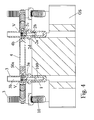
- said traditional modular components - which are shown in figs. 1, 2, 3 and 4 - are represented by implants (1, 10) adapted to be screwed onto the bone (OS) and by connection means (2, 20) engaged and fixed on top of said implants (1).
- Each implant (1, 10) basically consists in a pointed metal pin with external thread that is axially crossed by a blind cylindrical hole (100).
- connection means (2, 20) which is crossed by an axial cylindrical hole (2a), is composed of a first basically cylindrical section (2b) and a second truncated-conical section (2c) joined by an intermediate flange (2d).
- each connection means (2, 20) is adapted to be exactly inserted and screwed in correspondence of the end of said axial cylindrical hole (100) of the implant (1, 10), whereas the truncated-conical section (2c) is designed to be engaged into the end of a corresponding stump (3).
- the two central implants (1) are engaged in the bone (OS) in basically vertical position, whereas the two distal implants (10) are engaged in the bone (OS) in inclined position.
- connection means (2) adapted to cooperate with the central implants (1) have a basically rectilinear profile, wherein said cylindrical section (2b) and said truncated-conical section (2c) have coincident axes.
- connection means (20) adapted to cooperate with the distal implants (10) have an "angled" profile, wherein the two cylindrical and truncated-conical sections have intersecting axes.
- the modular components of the apparatus of the invention are adapted to cooperate with a structure obtained by assembling said traditional components (1, 10 / 2, 20).
- the first component of the new apparatus consists in a stump (3), basically formed of an externally corrugated cylindrical tubular stem with tapered point (3').
- Such a stump (3) is crossed, for most of its length, by a cylindrical hole (3b) joined, by means of a collar (3c) centrally crossed by a circular hole with lower section (3c'), with a truncated-conical seat (3d) basically obtained at the height of said head (3a).
- each of said stumps (3) is adapted to be prismatically coupled with one of said connection means (2, 20).
- said coupling provides for the truncated-conical seat (3d) of each stump (3) to be exactly penetrated by the corresponding truncated-conical section (2c) of the connection means (2, 20).
- Said coupling can be stabilized by means of suitable fixing screws (V), each of them being adapted to be inserted in the corresponding stump (3) starting from the tapered point of the latter and brought towards the bottom of said cylindrical hole (3b) of the latter, until the enlarged head stops against said internal collar (3c) of the stump (3).
- the additional components of the apparatus of the invention are used to mutually connect said stumps (3) and consequently also the corresponding implants (1, 10).
- connection between two adjacent stumps (3) is entrusted to a rod with horizontal axis (A), which is expressly shown in figs. 1 and 3 , obtained from the cooperation of two easy-to-couple modular components (4, 5).
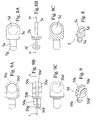
- the first of said component consists in an externally corrugated tubular cylindrical bar (4) that is provided at one end, with interposition of a plate (4a), with ear (4b) having a basically arched profile.
- Said ear (4b) is crossed by a circular hole (4c) with axis perpendicular to the axis of said bar (4), provided with basically identical section as said stump (3).
- the thickness (S) of said ear (4b) is significantly lower than the diameter of the corresponding tubular cylindrical bar (4).
- the component adapted to cooperate with a similar bar (4) consists in a clip (5), formed of a short cylindrical stem (5a) that protrudes, with interposition of a plate (5b), on the back of an ear (5c) provided with circular hole (5d); it being provided that said plate (5b) and ear (5c) have exactly the same shape and size as the components (4a, 4b) provided on said bar (4).
- said cylindrical stem (5a) is longitudinally cut by a central notch (5f) that extends from the tapered point almost to the connection point with said plate (5b).
- a slightly enlarged perimeter border (5g) is provided, with diameter slightly higher than the internal diameter of said tubular cylindrical bar (4).
- Said stem (5a) is adapted to be slightly forced in order to penetrate and remain blocked into the free end of a specimen of said bar (4).
- said bar (4) is adapted to cooperate, alternatively, also with a second embodiment of said clip (50).
- Said second clip (50) is provided with a basically identical structure as the first embodiment (5), as illustrated above, except for it is provided with two identical ears (50c) in perfectly specular position and separated by a space (50c') basically having the same height as the thickness (S) of the individual ear (5c) provided in the first embodiment of said clip (5).
- FIGS 9 and 9B illustrate the second embodiment of the clip (50), also with reference to the fact that said ears (50c) have a total thickness, including the space (50c'), that is basically identical to the width of the plate (50b).
- the second embodiment of the clip (50) is adapted to be disposed in correspondence of the free end of a corresponding bar (4), as illustrated above for the first embodiment (5), and therefore because of the forced insertion of its end (50a), which is also provided with a central longitudinal notch (50f) and enlarged perimeter border (50g) near the tapered point.
- a first specimen of bar (4) is coupled with the first embodiment (5) of the clip, whereas a second specimen of said bar (4) is coupled with the second embodiment (50) of the clip.
- the hole (4c or 5d) of the individual ear (4b or 5c) of the first specimen of bar must be perfectly aligned with the holes (50d) obtained in correspondence of the pair of ears (50c) provided in the second specimen of bar.
- the clip (5) provided with an individual ear (5c) is defined as “male element” and the clip (50) with the pair of ears (50c) is defined as “female element”.
- male element is used also to indicate the end of the bar (4) associated with the corresponding ear (4b).
- each of said bars (4) is adapted, before being coupled with the corresponding clip (5, 50), to be cut to size, in such a way that its total length, also including the clip, is exactly equal to the distance between the two adjacent stumps (3) to be connected.
- said stump (3) can be made according to multiple alternative embodiments, which only differ in the height (h) of the enlarged head (3a).
- Implants (1, 10) may protrude differently, even though with minimum differential values, from the bone (OS) where they are implanted.
- stumps (3) with heads (3a) of different heights (h) allows for efficaciously recuperating said differences in height that may occur between different implants (1, 10).
- a stump (3) provided with head (3a) with lower height must be mounted on the implant (1, 10) that protrudes the most from the bone (OS), whereas a stump (3) provided with head with higher height must be mounted on the implant (1, 10) that protrudes the least from the bone (OS).
- each stump (3) may be subject, possibly because of the stress caused by the normal use of the prosthesis, to simultaneous traction from opposite sides, respectively exerted by the female element of a bar (4) and the male element of the other bar.
- FIG. 7 shows an alternative embodiment (40) of the bar illustrated in Fig. 6A .
- the peculiarity of the second embodiment of bar (40) is that the ear (40b), which protrudes from a plate (40a), is provided with hole (40c) with slightly elliptical, and therefore not perfectly circular, profile.
- Such an embodiment of the bar (40) is advantageously used when the stump (3) in which the ear (40b) is to be inserted has a slight, undesired inclination, with respect to the perfect vertical, following to a similar misalignment of the implant (1, 10).
- said elliptical hole (40c) allows for achieving the ideal "stop", given the fact that the "looser” profile of the hole (40c) allows for neutralizing the few degrees of undesired inclination of the stump (3).
- a further clarification refers to the presence of the external corrugated surface finish on each stump (3) and each bar (4).
- Such a condition is provided to allow the resin used for the base of the multiple dental prosthesis for firmly anchoring against the external surface of the two components (3, 4).
- connection means (2, 20) in intermediate position between implants (1, 10) and stumps (3).
- connection means (2, 20) referred to in the present description are only necessary when some of the implants (1, 10) are implanted in the patient's bone (OS) in inclined position, as in the case of the distal implants (10) shown in figs. 1 to 4 .
- connection means would be superfluous and therefore - as illustrated above - the stumps (3) could be directly coupled with the corresponding implants (1, 10).
Landscapes
- Health & Medical Sciences (AREA)
- Animal Behavior & Ethology (AREA)
- Public Health (AREA)
- Dentistry (AREA)
- Epidemiology (AREA)
- Life Sciences & Earth Sciences (AREA)
- Oral & Maxillofacial Surgery (AREA)
- General Health & Medical Sciences (AREA)
- Veterinary Medicine (AREA)
- Orthopedic Medicine & Surgery (AREA)
- Engineering & Computer Science (AREA)
- Ceramic Engineering (AREA)
- Prostheses (AREA)
- Dental Prosthetics (AREA)
- Dental Tools And Instruments Or Auxiliary Dental Instruments (AREA)
Priority Applications (8)
| Application Number | Priority Date | Filing Date | Title |
|---|---|---|---|
| PT114250327T PT2489328E (pt) | 2011-02-17 | 2011-02-17 | Superstrutura de armação modular para implantes dentários |
| EP11425032A EP2489328B1 (de) | 2011-02-17 | 2011-02-17 | Modularer Gerüstaufbau für Zahnimplantate |
| RU2013142100/14A RU2586971C2 (ru) | 2011-02-17 | 2011-12-12 | Модульная каркасная покрывная конструкция для зубных имплантатов |
| US13/984,958 US8920171B2 (en) | 2011-02-17 | 2011-12-12 | Modular framework suprastructure for dental implants |
| PCT/EP2011/072448 WO2012110137A1 (en) | 2011-02-17 | 2011-12-12 | Modular framework suprastrcucture for dental implants |
| CN201180067856.5A CN103370030B (zh) | 2011-02-17 | 2011-12-12 | 用于种植牙的模块结构的上部构造 |
| UAA201310233A UA109047C2 (en) | 2011-02-17 | 2011-12-12 | MODULAR FRAMEWORK SUPERSTRUCTURE FOR DENTAL IMPLANTS |
| TNP2013000334A TN2013000334A1 (en) | 2011-02-17 | 2013-08-02 | Modular framework suprastrcucture for dental implants |
Applications Claiming Priority (1)
| Application Number | Priority Date | Filing Date | Title |
|---|---|---|---|
| EP11425032A EP2489328B1 (de) | 2011-02-17 | 2011-02-17 | Modularer Gerüstaufbau für Zahnimplantate |
Publications (2)
| Publication Number | Publication Date |
|---|---|
| EP2489328A1 true EP2489328A1 (de) | 2012-08-22 |
| EP2489328B1 EP2489328B1 (de) | 2013-03-27 |
Family
ID=44303223
Family Applications (1)
| Application Number | Title | Priority Date | Filing Date |
|---|---|---|---|
| EP11425032A Active EP2489328B1 (de) | 2011-02-17 | 2011-02-17 | Modularer Gerüstaufbau für Zahnimplantate |
Country Status (8)
| Country | Link |
|---|---|
| US (1) | US8920171B2 (de) |
| EP (1) | EP2489328B1 (de) |
| CN (1) | CN103370030B (de) |
| PT (1) | PT2489328E (de) |
| RU (1) | RU2586971C2 (de) |
| TN (1) | TN2013000334A1 (de) |
| UA (1) | UA109047C2 (de) |
| WO (1) | WO2012110137A1 (de) |
Cited By (5)
| Publication number | Priority date | Publication date | Assignee | Title |
|---|---|---|---|---|
| EP2913023A1 (de) * | 2014-02-26 | 2015-09-02 | P.P.M. S.R.L. di Giacomini Manuele e Monica | Set von Elementen und Verfahren zur Herstellung einer Verstärkungsstruktur |
| WO2017009407A1 (de) * | 2015-07-15 | 2017-01-19 | Nt-Trading Gmbh & Co. Kg | Positionsaufnahmevorrichtung für zahnimplantate |
| ITUA20163874A1 (it) * | 2016-05-27 | 2017-11-27 | Errecieffe S R L | Insieme per l'ancoraggio di una protesi dentale |
| IT201800006689A1 (it) * | 2018-06-26 | 2019-12-26 | Elemento posizionatore sotto-gengivale di impianti per un innesto osseo | |
| CN112451138A (zh) * | 2020-11-24 | 2021-03-09 | 北京联袂义齿技术有限公司 | 一种牙科栓体栓道附着体用法 |
Families Citing this family (2)
| Publication number | Priority date | Publication date | Assignee | Title |
|---|---|---|---|---|
| BR112017000475A2 (pt) * | 2014-07-23 | 2017-11-07 | Bacchiocchi Danilo | aparelho modular para a instalação de múltiplas próteses dentárias |
| EP3755265B1 (de) | 2018-02-20 | 2024-10-09 | Lambert J. Stumpel | Modularer träger für zahnprothese |
Citations (4)
| Publication number | Priority date | Publication date | Assignee | Title |
|---|---|---|---|---|
| DE19748268A1 (de) * | 1997-10-31 | 1999-05-12 | Kirsch Axel | Verfahren zum Herstellen eines Stegs zur Befestigung von Zahnersatz |
| US6692254B1 (en) * | 2002-02-01 | 2004-02-17 | Barry A. Kligerman | Implant supported dental prosthesis foundation bar |
| WO2006038877A1 (en) * | 2004-10-07 | 2006-04-13 | Dan Lundgren Ab | A prosthetic structure and a method for producing prosthetic structure |
| WO2009033297A1 (de) * | 2007-09-12 | 2009-03-19 | Cendres + Métaux Sa | Anordnung zur bildung einer stegkonstruktion und fixationsschraube dafür |
Family Cites Families (16)
| Publication number | Priority date | Publication date | Assignee | Title |
|---|---|---|---|---|
| CH619856A5 (de) | 1979-09-11 | 1980-10-31 | Elgarden Nv | |
| US5006069A (en) * | 1988-11-02 | 1991-04-09 | Implant Innovations, Inc. | Periodontal restoration components |
| CH686114A5 (fr) * | 1991-09-27 | 1996-01-15 | Helmut Hader | Structure de support d'une prothese dentaire. |
| JPH1015701A (ja) | 1996-07-04 | 1998-01-20 | Mitsubishi Materials Corp | 振動バイトによる切削方法 |
| CN2262083Y (zh) * | 1996-10-18 | 1997-09-10 | 成都三强实业公司 | 门铰链 |
| FI971622L (fi) * | 1997-04-17 | 1998-10-18 | Kari Luotio | Hammasimplanttijärjestelmä ja menetelmä sen valmistamiseksi |
| DE19931837B4 (de) * | 1999-07-09 | 2006-05-11 | OBE OHNMACHT & BAUMGäRTNER GMBH & CO. KG | Schraubverbindung für Scharnierteile |
| NL1017284C2 (nl) * | 2001-02-05 | 2002-08-06 | Accius Bv | Bevestigingsinrichting voor een orthese of prothese. |
| US6905336B2 (en) * | 2002-07-23 | 2005-06-14 | Robert Summers | Impression support system for dental implants |
| US7021934B2 (en) * | 2003-01-21 | 2006-04-04 | Zimmer Dental, Inc. | Multi-adjustable drill guide and framework system for dental prosthetics |
| CN2714880Y (zh) * | 2004-05-18 | 2005-08-03 | 兆利科技工业股份有限公司 | 转轴结构 |
| CN2937397Y (zh) * | 2006-05-08 | 2007-08-22 | 沈春生 | 玻璃铰链改良结构 |
| EP2103275A1 (de) * | 2008-03-19 | 2009-09-23 | Cerim AG | Zahnbrücke |
| TW201247177A (en) | 2008-06-11 | 2012-12-01 | Accentu8 Novotecnica Pty Ltd | Dentures, dental arches and methods of manufacture |
| CA2639721A1 (en) | 2008-09-22 | 2010-03-22 | Eric Allaire | Dental bar implant system |
| CN201680129U (zh) * | 2010-04-12 | 2010-12-22 | 中国科学院西安光学精密机械研究所 | 一种柔性接头及柔性连接装置 |
-
2011
- 2011-02-17 EP EP11425032A patent/EP2489328B1/de active Active
- 2011-02-17 PT PT114250327T patent/PT2489328E/pt unknown
- 2011-12-12 CN CN201180067856.5A patent/CN103370030B/zh active Active
- 2011-12-12 US US13/984,958 patent/US8920171B2/en active Active
- 2011-12-12 RU RU2013142100/14A patent/RU2586971C2/ru active
- 2011-12-12 UA UAA201310233A patent/UA109047C2/en unknown
- 2011-12-12 WO PCT/EP2011/072448 patent/WO2012110137A1/en not_active Ceased
-
2013
- 2013-08-02 TN TNP2013000334A patent/TN2013000334A1/fr unknown
Patent Citations (4)
| Publication number | Priority date | Publication date | Assignee | Title |
|---|---|---|---|---|
| DE19748268A1 (de) * | 1997-10-31 | 1999-05-12 | Kirsch Axel | Verfahren zum Herstellen eines Stegs zur Befestigung von Zahnersatz |
| US6692254B1 (en) * | 2002-02-01 | 2004-02-17 | Barry A. Kligerman | Implant supported dental prosthesis foundation bar |
| WO2006038877A1 (en) * | 2004-10-07 | 2006-04-13 | Dan Lundgren Ab | A prosthetic structure and a method for producing prosthetic structure |
| WO2009033297A1 (de) * | 2007-09-12 | 2009-03-19 | Cendres + Métaux Sa | Anordnung zur bildung einer stegkonstruktion und fixationsschraube dafür |
Cited By (9)
| Publication number | Priority date | Publication date | Assignee | Title |
|---|---|---|---|---|
| EP2913023A1 (de) * | 2014-02-26 | 2015-09-02 | P.P.M. S.R.L. di Giacomini Manuele e Monica | Set von Elementen und Verfahren zur Herstellung einer Verstärkungsstruktur |
| WO2017009407A1 (de) * | 2015-07-15 | 2017-01-19 | Nt-Trading Gmbh & Co. Kg | Positionsaufnahmevorrichtung für zahnimplantate |
| US10820973B2 (en) | 2015-07-15 | 2020-11-03 | Nt-Trading Gmbh & Co. Kg | Position capturing device for tooth implants |
| ITUA20163874A1 (it) * | 2016-05-27 | 2017-11-27 | Errecieffe S R L | Insieme per l'ancoraggio di una protesi dentale |
| WO2017203463A1 (en) * | 2016-05-27 | 2017-11-30 | Errecieffe S.R.L. | Anchoring assembly for a dental prosthesis |
| IT201800006689A1 (it) * | 2018-06-26 | 2019-12-26 | Elemento posizionatore sotto-gengivale di impianti per un innesto osseo | |
| WO2020003092A1 (en) * | 2018-06-26 | 2020-01-02 | Ennio Calabria | Subgingival implant adapt to retain implants in a bone graft |
| CN112451138A (zh) * | 2020-11-24 | 2021-03-09 | 北京联袂义齿技术有限公司 | 一种牙科栓体栓道附着体用法 |
| CN112451138B (zh) * | 2020-11-24 | 2022-02-18 | 北京联袂义齿技术有限公司 | 一种牙科栓体栓道附着体用法 |
Also Published As
| Publication number | Publication date |
|---|---|
| CN103370030B (zh) | 2016-02-24 |
| TN2013000334A1 (en) | 2015-01-20 |
| US8920171B2 (en) | 2014-12-30 |
| RU2013142100A (ru) | 2015-03-27 |
| US20140051034A1 (en) | 2014-02-20 |
| RU2586971C2 (ru) | 2016-06-10 |
| EP2489328B1 (de) | 2013-03-27 |
| WO2012110137A1 (en) | 2012-08-23 |
| CN103370030A (zh) | 2013-10-23 |
| UA109047C2 (en) | 2015-07-10 |
| PT2489328E (pt) | 2013-07-05 |
Similar Documents
| Publication | Publication Date | Title |
|---|---|---|
| EP2489328B1 (de) | Modularer Gerüstaufbau für Zahnimplantate | |
| JP2020062527A (ja) | 仮補綴システム及びその仮補綴システムの使用法 | |
| US20060216673A1 (en) | Dental implant | |
| CN111741731B (zh) | 牙齿修复体的模块化支持件 | |
| US20200093579A1 (en) | One piece custom made dental device for holding multiple teeth | |
| ES2541027T3 (es) | Implante dental | |
| KR102470652B1 (ko) | 향상된 체결구조를 갖는 임플란트용 임프레션 코핑 | |
| CN101530350B (zh) | 一种仿生牙种植体及其主根 | |
| KR101025225B1 (ko) | 치과용 임플란트의 픽스츄어 | |
| KR200483373Y1 (ko) | 스캔이 가능한 힐링 어버트먼트 세트 | |
| KR101015193B1 (ko) | 치과용 임플란트의 픽스츄어 | |
| JP2011525838A (ja) | 歯科用インプラント | |
| CN215425221U (zh) | 一种新型牙种植体 | |
| EP2752168A1 (de) | Zahnimplantat und prothesenbefestigungssystem mit verbindung zu diesem implantat mittels einer mechanischen feder ohne schrauben | |
| KR20080049377A (ko) | 나사풀림 방지구조를 갖는 임플란트 유닛 | |
| KR101505974B1 (ko) | 치과용 임플란트의 닻형 픽스츄어 | |
| CN201404302Y (zh) | 一种仿生牙种植体及其主根 | |
| KR102750328B1 (ko) | 보철 시스템 | |
| ITAN20110021A1 (it) | Attrezzatura modulare per la protesizzazione e la solidarizzazione di impianti dentali. | |
| EP2481372B1 (de) | Rückhaltesystem zur Fixierung einer Vollprothese im Unterkiefer | |
| KR100444319B1 (ko) | 인공치아 시스템의 지대치 | |
| KR102287204B1 (ko) | 치아 이식물 및 시술 가이드 | |
| JP6378541B2 (ja) | 歯科インプラントシステム | |
| KR20230079569A (ko) | 임플란트 시술을 위한 임프레션 코핑 | |
| CN116269863A (zh) | 一种采用可变形柱杆来实现双重防松功能的种植义齿 |
Legal Events
| Date | Code | Title | Description |
|---|---|---|---|
| PUAI | Public reference made under article 153(3) epc to a published international application that has entered the european phase |
Free format text: ORIGINAL CODE: 0009012 |
|
| 17P | Request for examination filed |
Effective date: 20110916 |
|
| AK | Designated contracting states |
Kind code of ref document: A1 Designated state(s): AL AT BE BG CH CY CZ DE DK EE ES FI FR GB GR HR HU IE IS IT LI LT LU LV MC MK MT NL NO PL PT RO RS SE SI SK SM TR |
|
| AX | Request for extension of the european patent |
Extension state: BA ME |
|
| GRAP | Despatch of communication of intention to grant a patent |
Free format text: ORIGINAL CODE: EPIDOSNIGR1 |
|
| RIC1 | Information provided on ipc code assigned before grant |
Ipc: A61C 13/275 20060101AFI20121026BHEP Ipc: A61C 8/00 20060101ALN20121026BHEP Ipc: A61C 13/273 20060101ALN20121026BHEP |
|
| GRAS | Grant fee paid |
Free format text: ORIGINAL CODE: EPIDOSNIGR3 |
|
| GRAA | (expected) grant |
Free format text: ORIGINAL CODE: 0009210 |
|
| AK | Designated contracting states |
Kind code of ref document: B1 Designated state(s): AL AT BE BG CH CY CZ DE DK EE ES FI FR GB GR HR HU IE IS IT LI LT LU LV MC MK MT NL NO PL PT RO RS SE SI SK SM TR |
|
| AX | Request for extension of the european patent |
Extension state: BA ME |
|
| REG | Reference to a national code |
Ref country code: GB Ref legal event code: FG4D |
|
| REG | Reference to a national code |
Ref country code: CH Ref legal event code: EP |
|
| REG | Reference to a national code |
Ref country code: AT Ref legal event code: REF Ref document number: 602871 Country of ref document: AT Kind code of ref document: T Effective date: 20130415 |
|
| REG | Reference to a national code |
Ref country code: IE Ref legal event code: FG4D |
|
| REG | Reference to a national code |
Ref country code: DE Ref legal event code: R096 Ref document number: 602011001181 Country of ref document: DE Effective date: 20130529 |
|
| REG | Reference to a national code |
Ref country code: PT Ref legal event code: SC4A Free format text: AVAILABILITY OF NATIONAL TRANSLATION Effective date: 20130626 |
|
| PG25 | Lapsed in a contracting state [announced via postgrant information from national office to epo] |
Ref country code: SE Free format text: LAPSE BECAUSE OF FAILURE TO SUBMIT A TRANSLATION OF THE DESCRIPTION OR TO PAY THE FEE WITHIN THE PRESCRIBED TIME-LIMIT Effective date: 20130327 Ref country code: BG Free format text: LAPSE BECAUSE OF FAILURE TO SUBMIT A TRANSLATION OF THE DESCRIPTION OR TO PAY THE FEE WITHIN THE PRESCRIBED TIME-LIMIT Effective date: 20130627 Ref country code: LT Free format text: LAPSE BECAUSE OF FAILURE TO SUBMIT A TRANSLATION OF THE DESCRIPTION OR TO PAY THE FEE WITHIN THE PRESCRIBED TIME-LIMIT Effective date: 20130327 Ref country code: NO Free format text: LAPSE BECAUSE OF FAILURE TO SUBMIT A TRANSLATION OF THE DESCRIPTION OR TO PAY THE FEE WITHIN THE PRESCRIBED TIME-LIMIT Effective date: 20130627 |
|
| REG | Reference to a national code |
Ref country code: DE Ref legal event code: R082 Ref document number: 602011001181 Country of ref document: DE Representative=s name: 2K PATENTANWAELTE BLASBERG KEWITZ & REICHEL PA, DE Ref country code: CH Ref legal event code: NV Representative=s name: OFFICE ERNEST T. FREYLINGER S.A., CH Ref country code: DE Ref legal event code: R082 Ref document number: 602011001181 Country of ref document: DE Representative=s name: 2K PATENTANWAELTE BLASBERG KEWITZ & REICHEL, P, DE |
|
| REG | Reference to a national code |
Ref country code: AT Ref legal event code: MK05 Ref document number: 602871 Country of ref document: AT Kind code of ref document: T Effective date: 20130327 |
|
| REG | Reference to a national code |
Ref country code: LT Ref legal event code: MG4D |
|
| PG25 | Lapsed in a contracting state [announced via postgrant information from national office to epo] |
Ref country code: FI Free format text: LAPSE BECAUSE OF FAILURE TO SUBMIT A TRANSLATION OF THE DESCRIPTION OR TO PAY THE FEE WITHIN THE PRESCRIBED TIME-LIMIT Effective date: 20130327 Ref country code: LV Free format text: LAPSE BECAUSE OF FAILURE TO SUBMIT A TRANSLATION OF THE DESCRIPTION OR TO PAY THE FEE WITHIN THE PRESCRIBED TIME-LIMIT Effective date: 20130327 Ref country code: GR Free format text: LAPSE BECAUSE OF FAILURE TO SUBMIT A TRANSLATION OF THE DESCRIPTION OR TO PAY THE FEE WITHIN THE PRESCRIBED TIME-LIMIT Effective date: 20130628 Ref country code: SI Free format text: LAPSE BECAUSE OF FAILURE TO SUBMIT A TRANSLATION OF THE DESCRIPTION OR TO PAY THE FEE WITHIN THE PRESCRIBED TIME-LIMIT Effective date: 20130327 |
|
| REG | Reference to a national code |
Ref country code: NL Ref legal event code: VDEP Effective date: 20130327 |
|
| PG25 | Lapsed in a contracting state [announced via postgrant information from national office to epo] |
Ref country code: HR Free format text: LAPSE BECAUSE OF FAILURE TO SUBMIT A TRANSLATION OF THE DESCRIPTION OR TO PAY THE FEE WITHIN THE PRESCRIBED TIME-LIMIT Effective date: 20130327 Ref country code: BE Free format text: LAPSE BECAUSE OF FAILURE TO SUBMIT A TRANSLATION OF THE DESCRIPTION OR TO PAY THE FEE WITHIN THE PRESCRIBED TIME-LIMIT Effective date: 20130327 |
|
| PG25 | Lapsed in a contracting state [announced via postgrant information from national office to epo] |
Ref country code: AT Free format text: LAPSE BECAUSE OF FAILURE TO SUBMIT A TRANSLATION OF THE DESCRIPTION OR TO PAY THE FEE WITHIN THE PRESCRIBED TIME-LIMIT Effective date: 20130327 Ref country code: IS Free format text: LAPSE BECAUSE OF FAILURE TO SUBMIT A TRANSLATION OF THE DESCRIPTION OR TO PAY THE FEE WITHIN THE PRESCRIBED TIME-LIMIT Effective date: 20130727 Ref country code: NL Free format text: LAPSE BECAUSE OF FAILURE TO SUBMIT A TRANSLATION OF THE DESCRIPTION OR TO PAY THE FEE WITHIN THE PRESCRIBED TIME-LIMIT Effective date: 20130327 Ref country code: SK Free format text: LAPSE BECAUSE OF FAILURE TO SUBMIT A TRANSLATION OF THE DESCRIPTION OR TO PAY THE FEE WITHIN THE PRESCRIBED TIME-LIMIT Effective date: 20130327 Ref country code: EE Free format text: LAPSE BECAUSE OF FAILURE TO SUBMIT A TRANSLATION OF THE DESCRIPTION OR TO PAY THE FEE WITHIN THE PRESCRIBED TIME-LIMIT Effective date: 20130327 Ref country code: CZ Free format text: LAPSE BECAUSE OF FAILURE TO SUBMIT A TRANSLATION OF THE DESCRIPTION OR TO PAY THE FEE WITHIN THE PRESCRIBED TIME-LIMIT Effective date: 20130327 Ref country code: ES Free format text: LAPSE BECAUSE OF FAILURE TO SUBMIT A TRANSLATION OF THE DESCRIPTION OR TO PAY THE FEE WITHIN THE PRESCRIBED TIME-LIMIT Effective date: 20130708 Ref country code: RO Free format text: LAPSE BECAUSE OF FAILURE TO SUBMIT A TRANSLATION OF THE DESCRIPTION OR TO PAY THE FEE WITHIN THE PRESCRIBED TIME-LIMIT Effective date: 20130327 |
|
| PG25 | Lapsed in a contracting state [announced via postgrant information from national office to epo] |
Ref country code: CY Free format text: LAPSE BECAUSE OF FAILURE TO SUBMIT A TRANSLATION OF THE DESCRIPTION OR TO PAY THE FEE WITHIN THE PRESCRIBED TIME-LIMIT Effective date: 20130327 Ref country code: PL Free format text: LAPSE BECAUSE OF FAILURE TO SUBMIT A TRANSLATION OF THE DESCRIPTION OR TO PAY THE FEE WITHIN THE PRESCRIBED TIME-LIMIT Effective date: 20130327 |
|
| PG25 | Lapsed in a contracting state [announced via postgrant information from national office to epo] |
Ref country code: DK Free format text: LAPSE BECAUSE OF FAILURE TO SUBMIT A TRANSLATION OF THE DESCRIPTION OR TO PAY THE FEE WITHIN THE PRESCRIBED TIME-LIMIT Effective date: 20130327 |
|
| PLBE | No opposition filed within time limit |
Free format text: ORIGINAL CODE: 0009261 |
|
| STAA | Information on the status of an ep patent application or granted ep patent |
Free format text: STATUS: NO OPPOSITION FILED WITHIN TIME LIMIT |
|
| 26N | No opposition filed |
Effective date: 20140103 |
|
| REG | Reference to a national code |
Ref country code: DE Ref legal event code: R097 Ref document number: 602011001181 Country of ref document: DE Effective date: 20140103 |
|
| PG25 | Lapsed in a contracting state [announced via postgrant information from national office to epo] |
Ref country code: MT Free format text: LAPSE BECAUSE OF FAILURE TO SUBMIT A TRANSLATION OF THE DESCRIPTION OR TO PAY THE FEE WITHIN THE PRESCRIBED TIME-LIMIT Effective date: 20130327 |
|
| REG | Reference to a national code |
Ref country code: FR Ref legal event code: PLFP Year of fee payment: 6 |
|
| PG25 | Lapsed in a contracting state [announced via postgrant information from national office to epo] |
Ref country code: SM Free format text: LAPSE BECAUSE OF FAILURE TO SUBMIT A TRANSLATION OF THE DESCRIPTION OR TO PAY THE FEE WITHIN THE PRESCRIBED TIME-LIMIT Effective date: 20130327 |
|
| PG25 | Lapsed in a contracting state [announced via postgrant information from national office to epo] |
Ref country code: RS Free format text: LAPSE BECAUSE OF FAILURE TO SUBMIT A TRANSLATION OF THE DESCRIPTION OR TO PAY THE FEE WITHIN THE PRESCRIBED TIME-LIMIT Effective date: 20130327 |
|
| PG25 | Lapsed in a contracting state [announced via postgrant information from national office to epo] |
Ref country code: TR Free format text: LAPSE BECAUSE OF FAILURE TO SUBMIT A TRANSLATION OF THE DESCRIPTION OR TO PAY THE FEE WITHIN THE PRESCRIBED TIME-LIMIT Effective date: 20130327 Ref country code: HU Free format text: LAPSE BECAUSE OF FAILURE TO SUBMIT A TRANSLATION OF THE DESCRIPTION OR TO PAY THE FEE WITHIN THE PRESCRIBED TIME-LIMIT; INVALID AB INITIO Effective date: 20110217 |
|
| REG | Reference to a national code |
Ref country code: FR Ref legal event code: PLFP Year of fee payment: 7 |
|
| REG | Reference to a national code |
Ref country code: FR Ref legal event code: PLFP Year of fee payment: 8 |
|
| PG25 | Lapsed in a contracting state [announced via postgrant information from national office to epo] |
Ref country code: MK Free format text: LAPSE BECAUSE OF FAILURE TO SUBMIT A TRANSLATION OF THE DESCRIPTION OR TO PAY THE FEE WITHIN THE PRESCRIBED TIME-LIMIT Effective date: 20130327 |
|
| PG25 | Lapsed in a contracting state [announced via postgrant information from national office to epo] |
Ref country code: AL Free format text: LAPSE BECAUSE OF FAILURE TO SUBMIT A TRANSLATION OF THE DESCRIPTION OR TO PAY THE FEE WITHIN THE PRESCRIBED TIME-LIMIT Effective date: 20130327 |
|
| PGFP | Annual fee paid to national office [announced via postgrant information from national office to epo] |
Ref country code: PT Payment date: 20250122 Year of fee payment: 15 |
|
| PGFP | Annual fee paid to national office [announced via postgrant information from national office to epo] |
Ref country code: CH Payment date: 20250301 Year of fee payment: 15 |
|
| PGFP | Annual fee paid to national office [announced via postgrant information from national office to epo] |
Ref country code: LU Payment date: 20260121 Year of fee payment: 16 |
|
| REG | Reference to a national code |
Ref country code: CH Ref legal event code: U11 Free format text: ST27 STATUS EVENT CODE: U-0-0-U10-U11 (AS PROVIDED BY THE NATIONAL OFFICE) Effective date: 20260301 |
|
| PGFP | Annual fee paid to national office [announced via postgrant information from national office to epo] |
Ref country code: GB Payment date: 20260121 Year of fee payment: 16 |
|
| PGFP | Annual fee paid to national office [announced via postgrant information from national office to epo] |
Ref country code: MC Payment date: 20260128 Year of fee payment: 16 |
|
| PGFP | Annual fee paid to national office [announced via postgrant information from national office to epo] |
Ref country code: IE Payment date: 20260123 Year of fee payment: 16 Ref country code: DE Payment date: 20260121 Year of fee payment: 16 |
|
| PGFP | Annual fee paid to national office [announced via postgrant information from national office to epo] |
Ref country code: IT Payment date: 20260121 Year of fee payment: 16 |
|
| PGFP | Annual fee paid to national office [announced via postgrant information from national office to epo] |
Ref country code: FR Payment date: 20260121 Year of fee payment: 16 |