EP2489611A1 - Dispositif de transport doté d'un moyen de traction sans fin entraîné pour produits de l'industrie de traitement du tabac - Google Patents
Dispositif de transport doté d'un moyen de traction sans fin entraîné pour produits de l'industrie de traitement du tabac Download PDFInfo
- Publication number
- EP2489611A1 EP2489611A1 EP12154816A EP12154816A EP2489611A1 EP 2489611 A1 EP2489611 A1 EP 2489611A1 EP 12154816 A EP12154816 A EP 12154816A EP 12154816 A EP12154816 A EP 12154816A EP 2489611 A1 EP2489611 A1 EP 2489611A1
- Authority
- EP
- European Patent Office
- Prior art keywords
- endless
- recesses
- conveying device
- guide member
- guide
- Prior art date
- Legal status (The legal status is an assumption and is not a legal conclusion. Google has not performed a legal analysis and makes no representation as to the accuracy of the status listed.)
- Granted
Links
- 241000208125 Nicotiana Species 0.000 title claims description 10
- 235000002637 Nicotiana tabacum Nutrition 0.000 title claims description 10
- 230000001360 synchronised effect Effects 0.000 claims description 17
- 239000000047 product Substances 0.000 description 11
- 239000012043 crude product Substances 0.000 description 4
- 239000000835 fiber Substances 0.000 description 3
- 241000282472 Canis lupus familiaris Species 0.000 description 2
- 238000011161 development Methods 0.000 description 2
- 230000018109 developmental process Effects 0.000 description 2
- 229920001971 elastomer Polymers 0.000 description 2
- 239000000806 elastomer Substances 0.000 description 2
- 239000004744 fabric Substances 0.000 description 2
- 239000000463 material Substances 0.000 description 2
- 241000196324 Embryophyta Species 0.000 description 1
- 230000002411 adverse Effects 0.000 description 1
- 239000013590 bulk material Substances 0.000 description 1
- 239000000969 carrier Substances 0.000 description 1
- 239000002131 composite material Substances 0.000 description 1
- 238000007598 dipping method Methods 0.000 description 1
- 239000011888 foil Substances 0.000 description 1
- 229920003023 plastic Polymers 0.000 description 1
- 239000004033 plastic Substances 0.000 description 1
- 229920000728 polyester Polymers 0.000 description 1
- 230000007704 transition Effects 0.000 description 1
Images


Classifications
-
- B—PERFORMING OPERATIONS; TRANSPORTING
- B65—CONVEYING; PACKING; STORING; HANDLING THIN OR FILAMENTARY MATERIAL
- B65G—TRANSPORT OR STORAGE DEVICES, e.g. CONVEYORS FOR LOADING OR TIPPING, SHOP CONVEYOR SYSTEMS OR PNEUMATIC TUBE CONVEYORS
- B65G15/00—Conveyors having endless load-conveying surfaces, i.e. belts and like continuous members, to which tractive effort is transmitted by means other than endless driving elements of similar configuration
- B65G15/60—Arrangements for supporting or guiding belts, e.g. by fluid jets
-
- B—PERFORMING OPERATIONS; TRANSPORTING
- B65—CONVEYING; PACKING; STORING; HANDLING THIN OR FILAMENTARY MATERIAL
- B65G—TRANSPORT OR STORAGE DEVICES, e.g. CONVEYORS FOR LOADING OR TIPPING, SHOP CONVEYOR SYSTEMS OR PNEUMATIC TUBE CONVEYORS
- B65G23/00—Driving gear for endless conveyors; Belt- or chain-tensioning arrangements
- B65G23/02—Belt- or chain-engaging elements
- B65G23/04—Drums, rollers, or wheels
- B65G23/06—Drums, rollers, or wheels with projections engaging abutments on belts or chains, e.g. sprocket wheels
Definitions
- the invention relates to a conveyor with a driven Endloszugsch for products of the tobacco processing industry with at least one deflecting device on which the endless traction means is deflected on the outside, wherein the endless traction means has outwardly projecting driver for taking the products.
- Conveyors with driven endless draw means are used, for example, to feed crude products, such as cut tobacco fibers, to a further processing station, the crude product being transported as bulk material over a horizontal distance or via an inclined section to a delivery location.
- the crude product is thereby applied to the endless draw and taken by a plurality of arranged on the endless traction means drivers.
- the entrainers can be designed either as continuous rails protruding from the endless traction means or as protruding tines.
- the drivers can also be formed from a combination of a continuous rail with projecting tines.
- the continuous draw means itself can be made of a fabric band or of a fabric-reinforced elastomer strap.
- the endless traction means must be deflected several times during the conveying movement at different deflection points, and can be divided into an upper strand and a lower strand.
- the upper run is the portion of the endless draw means in which the product is transported from the feed to the discharge portion of the endless draw means
- the lower run is the portion of the endless draw means in which the endless draw means from the discharge section of the endless draw means at the bottom of the conveyor to the feed section is returned.
- the upper strand runs, according to its name, at the top of the conveyor, while the Untertrumm runs at the bottom.
- the endless draw means runs in the upper run from the horizontal feed section in an inclined section upwards to a turn horizontal delivery section.
- the task and / or delivery section can also run at an angle, or, depending on the geometry of the conveyor device, can only be designed very short or even not exist at all.
- the order is then reversed accordingly, with no product then rests on the lower strand of Endloszugstoffs.
- the endless traction means In the transition from the horizontal task section to the inclined section and from the inclined section to the horizontal delivery section, the endless traction means must each be deflected by abutment against an internally or externally arranged deflection device.
- the deflection of the endless traction means on the outside arranged deflection is to be considered that on the endless traction means the projecting Driver are provided.
- the outer-side deflection has been realized by the endless traction means is deflected and guided at several arranged at the edge of the endless traction means guide rollers so that the middle portion of the endless traction means can run freely with the drivers between the pulleys, and thereby inevitably not supported becomes.
- the inclined portion In the event that a large delivery height to be achieved with the conveyor, the inclined portion must be made relatively long and / or steep, the distances between the deflection of the endless traction means must then be chosen correspondingly large.
- This large distance in connection with the large width of the endless draw means disadvantageously has the consequence that the endless draw means inevitably bulges under its own weight and / or under the high tensile forces acting in the endless draw means in the area of the deflection device. Due to this resulting bulge, the guidance of the endless draw means and the stress distribution in the endless draw means are adversely affected, which in turn limits the maximum tensile force to be realized and the width of the endless draw means. Since the width of the endless traction means and the tensile force in the endless traction means are directly related to the conveying capacity of the conveyor, this also indirectly limits the maximum conveying capacity.
- the object of the invention is to provide a conveyor of the generic type with a higher, maximum to be realized delivery capacity.
- the deflection device is formed by a rotatably mounted guide part, which has a guide surface which is interrupted by regularly arranged recesses into which the drivers can be received.
- the guide member is formed as a disc.
- the design of the guide member as a disc has the advantage that the endless traction means can be supported even at a low space available for the guide part space on a large diameter.
- the guide member can be designed dimensionally stable at a low weight, the low transverse stability of the disc is not a disadvantage here, since the disc is substantially radially loaded in a support of the endless traction.
- At least two spaced and coaxially arranged, applied to the endless traction means discs are provided for guiding the endless drawing means.
- the support of the endless draw means can be further improved by distributing the bearing force over several disks or by supporting the endless draw means in several places.
- the discs are rotatably connected to each other. Due to the rotationally fixed connection of the discs, the relative orientation of the discs is fixed to each other after assembly, so that the discs can be brought as a package structurally simple in a spatial assignment to the incoming endless traction means with the projecting regularly projecting drivers.
- the discs can both be directly connected to each other and be rotatably mounted on a common shaft, it is only important that the orientation of the discs does not change during operation of the conveyor.
- the discs are arranged such that the recesses are aligned transversely to the movement of the endless drawing means.
- the recesses thus form a continuous channel in the aligned direction, whereby e.g. Carrier in the form of continuous straight rails can dive particularly well in the recesses of the parallel guide parts.
- the drivers themselves or in their entirety comprise or form a comb structure with individually protruding tines, and that the disks have a thickness which is smaller than the spacing of the tines.
- the discs can thereby dive through between the tines, so that the drivers themselves can be sized larger than the depth of the recesses in the height of the tines.
- the recesses may be formed by outwardly constricting pockets, which may account for the fact that the dogs pivot between the beginning of the plunging movement and the end of the exit movement with respect to the guide member while the plunging into the recesses Ends of the driver travel a greater distance relative to the guide member than the moving in the openings of the recesses initial sections of the driver.
- the recesses are shaped in such a way that, during the exit movement, the drivers come to bear against the edge of the guide part delimiting the recess, and that the guide part can thereby be driven to rotate.
- the guide member is thereby driven to a synchronized to the movement of the endless traction means rotational movement, so that the drivers and the recesses are automatically synchronized in pairs moved toward each other during the dipping movement of the driver. Due to the simple synchronized drive of the guide parts can be dispensed with a separate drive of the guide member, which in turn reduces costs and the design effort can be reduced.
- At least two drivers should always engage in different recesses of the guide member at the same time, so that during the drive of the guide member via a driver by the system at the edge of the recess at least one driver is already immersed in another recess, during the subsequent movement sequence continues the drive of the guide part.
- a continuous drive of the guide member is ensured.
- the simultaneous engagement of two drivers the synchronization can be improved, since the exit movement of one driver and the plunge movement of another driver always overlap in time, so that the plunging movement of the drivers into the recesses is controlled directly by the exit movement of the carriers emerging from the recesses.
- the guide member is rotatably connected to a synchronizing disc, and that the synchronizing disc driving pins and / or recesses, with which it is positively engageable with provided on the edge of the endless traction means recesses and / or driving pins into engagement. Due to the proposed synchronizing disk, the movement of the guide part can be synchronized in addition to or as an alternative to the proposed drive of the guide part via the drivers to the movement of the endless drawing means. Since the synchronizer disc is non-rotatably connected to the guide member, the rotational movement of the synchronizing disc can be equated with the rotational movement of the guide member.
- the movement of the endless traction means and the movement of the guide member can be synchronized by the endless traction means is drivable by means of a first drive means, and the guide member is driven by means of a synchronized to the first drive means second drive means.
- FIG. 1 a conveyor device 1 designed according to the invention can be seen with a continuous drawing means 2.
- the endless draw means 2 can be formed by a fabric strap, a fabric-reinforced elastomer strap or also of another material, which is sufficiently flexible and at the same time has the necessary tensile strength for transmitting the tensile force.
- the conveyor 1 has a horizontal feed section 9, a horizontal horizontal discharge section 11 and an oblique section 10 interconnecting the feed and discharge sections 9 and 11.
- this is provided on its inside with protruding cams 16, with which the endless traction means 2 positively engages in correspondingly shaped recesses of a drive drum 4, which in turn can be driven by a drive device, such as an electric motor.
- the endless draw means 2 is tensioned by means of a tensioning drum 5. Between the drive drum 4 and the tensioning drum 5 different deflection 6,7,8 and 29 are provided to guide the endless traction means 2 according to the above-described course.
- Outwardly projecting dogs 15 are provided on the outside of the endless drawing means 2, which convey the product from the loading section 9, the inclined section 10 up to the delivery section 11.
- Products which can be conveyed by means of the conveying device 1 described are, for example, tobacco fibers in various composite forms, loose tobacco fibers, raw tobacco, tobacco foil or expanded tobacco, which must be conveyed continuously for further processing.
- the endless draw means 2 can be subdivided in its course into an upper run 28 and a lower run 25, wherein the product is fed onto the upper run 28 and conveyed, while the endless draw means 2 in the lower run 25 is returned from the delivery section 11 to the feed section 9.
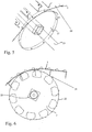
- the endless traction means 2 does not bulge on the deflection device 29 due to the high tensile forces and the large width, the deflection device 29 is inventively formed by the guide member 3, which subsequently in the FIGS. 2 to 8 will be described in more detail.
- the guide part 3 has a plurality of recesses 12 separated from each other, outwardly projecting fingers 13, whose end faces in the entirety form a guide surface 14 which is interrupted by the recesses 12. It is irrelevant to the functionality of the invention, whether the area ratio of the recesses 12 or the area ratio of the end faces of the fingers 13 make up the greater proportion of the circumference, it is only important that the end faces of the fingers 13 are formed so that they pass through the plant at the endless draw means 2 at least reduce the bulging of the endless draw means 2 in the region of the deflection device 29 and thereby together form a guide surface 14 during the course of the movement.
- the distances of the recesses 12 are chosen so that at least two of the drivers 15 simultaneously dive into different recesses 12. Further, the recesses 12 narrow outward, so that a total of a larger guide surface 14 results, and the driver 15 during the movement of the endless traction means 2 in the direction of arrow 31 can perform a pivoting movement in the recesses 12.
- the drivers 15 move out of the recesses 12 on the edge 17 of the recesses 12 during extension and thereby drive the guide member 3 in the direction of arrow 18 to a synchronous rotational movement. Due to the synchronous rotational movement in each case a recess 12 and a driver 15 in the starting region of the endless traction means 2 on the guide member 3 synchronously moved in pairs toward each other, so that a total of harmonious clamping movement of the guide member 3 results to the Endloszugstoff 2. In addition, the friction and wear of the endless traction means 2 and the guide member 3 can be significantly reduced by the synchronous rotation of the guide member.
- only one guide part 3 is always representative. It makes sense to support a relatively wide Endloszugstoffs 2 a plurality of identical guide members 3 are provided, which by means of engaging in corresponding recesses 24 of the guide members 3 shaft 23 rotatably and in identical alignment with each other are connected. The number and spacing of the guide parts 3 can be selected depending on the individual tensile force and surface load of the endless drawing means 2.
- the recesses 12 of the various guide parts 3 are in a fixed spatial relationship to each other and the auf wornden drivers 15, so that can be achieved with a correspondingly regular arrangement of the driver 15, a harmonious clamping movement sequence .
- the recesses 12 are aligned transversely to the direction of movement of the endless traction means 2, so that the drivers 15 can be designed as transversely aligned with the direction of movement of the endless traction means 2 rails, which in turn offers advantages for the transport of the product.
- the guide members 3 can be mounted as discs on the shaft 23, and thereby cause with sufficient mechanical support due to the small width only low frictional forces, which are also reduced to a minimum, since the guide parts 3 are driven synchronized by the endless traction means 2 and is thereby moved in the contact surface at the same speed. Furthermore, the use of discs as guide parts 3 is advantageous in that they require little space and can be manufactured inexpensively.
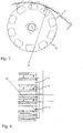
- FIGS. 3 and 4 shows a further development of the invention, in which the drivers 15 are provided at their ends with a comb structure 19 having a plurality of spaced tines 30.
- the distance of the tines 30 is greater than the thickness of the disc-shaped guide member 3 chosen so that the guide member 3 between the tines 30 dip can.
- FIGS. 5 and 6 is another preferred embodiment of the invention can be seen, in which the guide members 3 are rotatably connected to a laterally arranged synchronizing disc 22.
- the synchronizing disc 22 has a plurality of circumferentially, regularly arranged, projecting, radial driving pins 21 which engage during the pulling movement of the endless traction means 2 in corresponding, a row of holes forming recesses 20 in the edge of the endless traction means 2, whereby the synchronizing disc 22 itself and rotatably with the synchronizing disc 22 connected guide parts 3 are driven synchronously.
- FIGS. 7 and 8 is another embodiment of the invention can be seen, in which the synchronizing disc 22 is provided with laterally projecting driving pins 27 which come during the pulling movement of the endless traction means 2 for engagement in pocket-shaped, lateral recesses 26 of the endless traction means 2, whereby the synchronizing disc 22 and the guide parts. 3 again in the same way as in the FIGS. 5 and 6 be driven synchronized.
- the synchronized movement of the guide parts 3 can also be effected by a separate drive device which is itself synchronized to the drive means of the endless drawing means 2.
Landscapes
- Engineering & Computer Science (AREA)
- Mechanical Engineering (AREA)
- Belt Conveyors (AREA)
- Toys (AREA)
- Attitude Control For Articles On Conveyors (AREA)
- Chain Conveyers (AREA)
Priority Applications (1)
| Application Number | Priority Date | Filing Date | Title |
|---|---|---|---|
| PL12154816T PL2489611T3 (pl) | 2011-02-16 | 2012-02-10 | Urządzenie przenośnikowe z napędzanym okrężnym środkiem ciągnącym do wyrobów przemysłu tytoniowego |
Applications Claiming Priority (1)
| Application Number | Priority Date | Filing Date | Title |
|---|---|---|---|
| DE102011011403A DE102011011403A1 (de) | 2011-02-16 | 2011-02-16 | Fördereinrichtung mit einem angetriebenen Endloszugmittel für Produkte der Tabak verarbeitenden Industrie |
Publications (2)
| Publication Number | Publication Date |
|---|---|
| EP2489611A1 true EP2489611A1 (fr) | 2012-08-22 |
| EP2489611B1 EP2489611B1 (fr) | 2014-04-02 |
Family
ID=45592207
Family Applications (1)
| Application Number | Title | Priority Date | Filing Date |
|---|---|---|---|
| EP12154816.8A Not-in-force EP2489611B1 (fr) | 2011-02-16 | 2012-02-10 | Dispositif de transport doté d'un moyen de traction sans fin entraîné pour produits de l'industrie de traitement du tabac |
Country Status (4)
| Country | Link |
|---|---|
| EP (1) | EP2489611B1 (fr) |
| CN (1) | CN102640987B (fr) |
| DE (1) | DE102011011403A1 (fr) |
| PL (1) | PL2489611T3 (fr) |
Cited By (2)
| Publication number | Priority date | Publication date | Assignee | Title |
|---|---|---|---|---|
| WO2016001027A1 (fr) * | 2014-06-30 | 2016-01-07 | Sig Technology Ag | Convoyeur à bande avec éléments en coin destinés à modifier la courbure au niveau des roues de renvoi |
| DE102017120700A1 (de) * | 2017-09-07 | 2019-03-07 | Khs Gmbh | Transportvorrichtung sowie Transportverfahren mit einer derartigen Transportvorrichtung |
Citations (8)
| Publication number | Priority date | Publication date | Assignee | Title |
|---|---|---|---|---|
| FR1178382A (fr) * | 1957-07-10 | 1959-05-06 | Cie Bordelaise Des Prod Chim | élévateur |
| US3521740A (en) * | 1968-04-16 | 1970-07-28 | Fmc Corp | Processing conveyor |
| AT339813B (de) * | 1975-11-21 | 1977-11-10 | Krobath Maschf Ferd | Vorrichtung zum abstutzen des leertrumes eines endlosen fordermittels bei stetigforderern |
| DE2719332A1 (de) * | 1977-04-30 | 1978-11-02 | Gewerk Eisenhuette Westfalia | Kurvenfoerderer |
| DE2839262A1 (de) * | 1978-09-09 | 1980-03-13 | Halbach & Braun | Kettenkratzfoerderer |
| EP0726215A1 (fr) * | 1995-02-09 | 1996-08-14 | ESI Engineers & Contractors B.V. | Installation de transport pour produits en vrac, poulie à poche et disque racleur pour celle-ci |
| US20060084542A1 (en) * | 2004-10-18 | 2006-04-20 | Tsubakimoto Chain Co. | Conveyance system |
| DE102007016287A1 (de) * | 2007-03-09 | 2008-09-11 | Gassner Ges.M.B.H. | Stollenband-Hochförderer |
Family Cites Families (2)
| Publication number | Priority date | Publication date | Assignee | Title |
|---|---|---|---|---|
| CH686506A5 (de) * | 1993-02-03 | 1996-04-15 | Werner Hunziker | Vorrichtung zum kontinuierlichen Foerdern und Drehen von Werkstuecken. |
| CN201438846U (zh) * | 2009-07-29 | 2010-04-21 | 山东中烟工业公司 | 烟草薄片线输送装置 |
-
2011
- 2011-02-16 DE DE102011011403A patent/DE102011011403A1/de not_active Withdrawn
-
2012
- 2012-02-10 EP EP12154816.8A patent/EP2489611B1/fr not_active Not-in-force
- 2012-02-10 PL PL12154816T patent/PL2489611T3/pl unknown
- 2012-02-15 CN CN201210033483.6A patent/CN102640987B/zh not_active Expired - Fee Related
Patent Citations (8)
| Publication number | Priority date | Publication date | Assignee | Title |
|---|---|---|---|---|
| FR1178382A (fr) * | 1957-07-10 | 1959-05-06 | Cie Bordelaise Des Prod Chim | élévateur |
| US3521740A (en) * | 1968-04-16 | 1970-07-28 | Fmc Corp | Processing conveyor |
| AT339813B (de) * | 1975-11-21 | 1977-11-10 | Krobath Maschf Ferd | Vorrichtung zum abstutzen des leertrumes eines endlosen fordermittels bei stetigforderern |
| DE2719332A1 (de) * | 1977-04-30 | 1978-11-02 | Gewerk Eisenhuette Westfalia | Kurvenfoerderer |
| DE2839262A1 (de) * | 1978-09-09 | 1980-03-13 | Halbach & Braun | Kettenkratzfoerderer |
| EP0726215A1 (fr) * | 1995-02-09 | 1996-08-14 | ESI Engineers & Contractors B.V. | Installation de transport pour produits en vrac, poulie à poche et disque racleur pour celle-ci |
| US20060084542A1 (en) * | 2004-10-18 | 2006-04-20 | Tsubakimoto Chain Co. | Conveyance system |
| DE102007016287A1 (de) * | 2007-03-09 | 2008-09-11 | Gassner Ges.M.B.H. | Stollenband-Hochförderer |
Cited By (3)
| Publication number | Priority date | Publication date | Assignee | Title |
|---|---|---|---|---|
| WO2016001027A1 (fr) * | 2014-06-30 | 2016-01-07 | Sig Technology Ag | Convoyeur à bande avec éléments en coin destinés à modifier la courbure au niveau des roues de renvoi |
| CN106573731A (zh) * | 2014-06-30 | 2017-04-19 | Sig技术股份公司 | 具有楔形元件以改变偏转轮处的曲率的皮带传送机 |
| DE102017120700A1 (de) * | 2017-09-07 | 2019-03-07 | Khs Gmbh | Transportvorrichtung sowie Transportverfahren mit einer derartigen Transportvorrichtung |
Also Published As
| Publication number | Publication date |
|---|---|
| CN102640987A (zh) | 2012-08-22 |
| PL2489611T3 (pl) | 2014-09-30 |
| EP2489611B1 (fr) | 2014-04-02 |
| CN102640987B (zh) | 2016-12-14 |
| DE102011011403A1 (de) | 2012-08-16 |
Similar Documents
| Publication | Publication Date | Title |
|---|---|---|
| EP2826735B1 (fr) | Section ajustable de stockage tampon d'un dispositif de convoyage et procédé de stockage intermédiaire d'articles | |
| CH701358A1 (de) | Fördereinrichtung und abstützvorrichtung. | |
| DE2618905B2 (de) | Zwischenspeicher in Form eines Übergabe-Förderers | |
| DE102008008009A1 (de) | Fördereinrichtung zum vertikalen Transport von Stückgut | |
| EP3205218B1 (fr) | Dispositif de transport d'un flux massique d'article sous forme de tige et son utilisation | |
| EP3529180B1 (fr) | Système de transport | |
| EP0541850B1 (fr) | Transporteur à palettes curviligne | |
| EP2314529B1 (fr) | Unité de transport dotée de chaînes à petits rouleaux de retenue | |
| DE102020129750A1 (de) | Verfahren zum Quer-Positionieren eines zu transportierenden Artikels | |
| EP2366640A2 (fr) | Unité de transport pour un système de transport pour articles | |
| EP2489611B1 (fr) | Dispositif de transport doté d'un moyen de traction sans fin entraîné pour produits de l'industrie de traitement du tabac | |
| EP0161412B1 (fr) | Dispositif de transport pour convoyer des montages supports de pièces | |
| EP0104366A1 (fr) | Convoyeur en continu, notamment convoyeur à chaînes porteuses | |
| EP2754626A1 (fr) | Dispositif convoyeur à courroie concave | |
| DE2434362A1 (de) | Laengsfoerderer mit einer einrichtung zum drehen quaderfoermiger gegenstaende, wie kaesten, kartons oder dgl. um ihre hochachse | |
| EP2589552B1 (fr) | Dispositif convoyeur doté d'un moyen de traction sans fin entraîné pour produits de l'industrie de traitement du tabac | |
| DE102025104511B3 (de) | Doppelbandförderer mit Zwischenantrieb | |
| DE10051790A1 (de) | Behälter, Vorrichtung und Verfahren zum Transportieren von stabförmigen Artikeln der tabakverarbeitenden Industrie | |
| DE3545389C2 (de) | Vereinzeler für Gegenstände | |
| DE3728881C2 (fr) | ||
| DE1008651B (de) | Kontinuierlich arbeitender Flaschenfoerderer mit endlosem Steilfoerderband und Foerderzellen bildenden starren Stegen | |
| EP0876288B1 (fr) | Dispositif de transport pour canaux menages entre des rayonnages d'entreposage | |
| WO2019197552A1 (fr) | Unité tablier-cribleur d'une récolteuse ou d'une unité de transport de produits de récolte | |
| DE2021143C (de) | Plattenförderer, insbesondere zum Fördern und Vereinzeln von Baumstammabschnitten oder dergleichen | |
| EP3533731A1 (fr) | Transporteur incliné |
Legal Events
| Date | Code | Title | Description |
|---|---|---|---|
| PUAI | Public reference made under article 153(3) epc to a published international application that has entered the european phase |
Free format text: ORIGINAL CODE: 0009012 |
|
| AK | Designated contracting states |
Kind code of ref document: A1 Designated state(s): AL AT BE BG CH CY CZ DE DK EE ES FI FR GB GR HR HU IE IS IT LI LT LU LV MC MK MT NL NO PL PT RO RS SE SI SK SM TR |
|
| AX | Request for extension of the european patent |
Extension state: BA ME |
|
| 17P | Request for examination filed |
Effective date: 20120915 |
|
| GRAP | Despatch of communication of intention to grant a patent |
Free format text: ORIGINAL CODE: EPIDOSNIGR1 |
|
| INTG | Intention to grant announced |
Effective date: 20131105 |
|
| GRAS | Grant fee paid |
Free format text: ORIGINAL CODE: EPIDOSNIGR3 |
|
| GRAA | (expected) grant |
Free format text: ORIGINAL CODE: 0009210 |
|
| AK | Designated contracting states |
Kind code of ref document: B1 Designated state(s): AL AT BE BG CH CY CZ DE DK EE ES FI FR GB GR HR HU IE IS IT LI LT LU LV MC MK MT NL NO PL PT RO RS SE SI SK SM TR |
|
| REG | Reference to a national code |
Ref country code: GB Ref legal event code: FG4D Free format text: NOT ENGLISH |
|
| REG | Reference to a national code |
Ref country code: CH Ref legal event code: EP Ref country code: AT Ref legal event code: REF Ref document number: 659962 Country of ref document: AT Kind code of ref document: T Effective date: 20140415 |
|
| REG | Reference to a national code |
Ref country code: IE Ref legal event code: FG4D Free format text: LANGUAGE OF EP DOCUMENT: GERMAN |
|
| REG | Reference to a national code |
Ref country code: DE Ref legal event code: R096 Ref document number: 502012000534 Country of ref document: DE Effective date: 20140515 |
|
| REG | Reference to a national code |
Ref country code: NL Ref legal event code: T3 |
|
| REG | Reference to a national code |
Ref country code: LT Ref legal event code: MG4D |
|
| REG | Reference to a national code |
Ref country code: PL Ref legal event code: T3 |
|
| PG25 | Lapsed in a contracting state [announced via postgrant information from national office to epo] |
Ref country code: BG Free format text: LAPSE BECAUSE OF FAILURE TO SUBMIT A TRANSLATION OF THE DESCRIPTION OR TO PAY THE FEE WITHIN THE PRESCRIBED TIME-LIMIT Effective date: 20140702 Ref country code: FI Free format text: LAPSE BECAUSE OF FAILURE TO SUBMIT A TRANSLATION OF THE DESCRIPTION OR TO PAY THE FEE WITHIN THE PRESCRIBED TIME-LIMIT Effective date: 20140402 Ref country code: CY Free format text: LAPSE BECAUSE OF FAILURE TO SUBMIT A TRANSLATION OF THE DESCRIPTION OR TO PAY THE FEE WITHIN THE PRESCRIBED TIME-LIMIT Effective date: 20140402 Ref country code: IS Free format text: LAPSE BECAUSE OF FAILURE TO SUBMIT A TRANSLATION OF THE DESCRIPTION OR TO PAY THE FEE WITHIN THE PRESCRIBED TIME-LIMIT Effective date: 20140802 Ref country code: LT Free format text: LAPSE BECAUSE OF FAILURE TO SUBMIT A TRANSLATION OF THE DESCRIPTION OR TO PAY THE FEE WITHIN THE PRESCRIBED TIME-LIMIT Effective date: 20140402 Ref country code: GR Free format text: LAPSE BECAUSE OF FAILURE TO SUBMIT A TRANSLATION OF THE DESCRIPTION OR TO PAY THE FEE WITHIN THE PRESCRIBED TIME-LIMIT Effective date: 20140703 Ref country code: NO Free format text: LAPSE BECAUSE OF FAILURE TO SUBMIT A TRANSLATION OF THE DESCRIPTION OR TO PAY THE FEE WITHIN THE PRESCRIBED TIME-LIMIT Effective date: 20140702 Ref country code: CZ Free format text: LAPSE BECAUSE OF FAILURE TO SUBMIT A TRANSLATION OF THE DESCRIPTION OR TO PAY THE FEE WITHIN THE PRESCRIBED TIME-LIMIT Effective date: 20140402 |
|
| PG25 | Lapsed in a contracting state [announced via postgrant information from national office to epo] |
Ref country code: LV Free format text: LAPSE BECAUSE OF FAILURE TO SUBMIT A TRANSLATION OF THE DESCRIPTION OR TO PAY THE FEE WITHIN THE PRESCRIBED TIME-LIMIT Effective date: 20140402 Ref country code: RS Free format text: LAPSE BECAUSE OF FAILURE TO SUBMIT A TRANSLATION OF THE DESCRIPTION OR TO PAY THE FEE WITHIN THE PRESCRIBED TIME-LIMIT Effective date: 20140402 Ref country code: HR Free format text: LAPSE BECAUSE OF FAILURE TO SUBMIT A TRANSLATION OF THE DESCRIPTION OR TO PAY THE FEE WITHIN THE PRESCRIBED TIME-LIMIT Effective date: 20140402 Ref country code: SE Free format text: LAPSE BECAUSE OF FAILURE TO SUBMIT A TRANSLATION OF THE DESCRIPTION OR TO PAY THE FEE WITHIN THE PRESCRIBED TIME-LIMIT Effective date: 20140402 Ref country code: ES Free format text: LAPSE BECAUSE OF FAILURE TO SUBMIT A TRANSLATION OF THE DESCRIPTION OR TO PAY THE FEE WITHIN THE PRESCRIBED TIME-LIMIT Effective date: 20140402 |
|
| PG25 | Lapsed in a contracting state [announced via postgrant information from national office to epo] |
Ref country code: PT Free format text: LAPSE BECAUSE OF FAILURE TO SUBMIT A TRANSLATION OF THE DESCRIPTION OR TO PAY THE FEE WITHIN THE PRESCRIBED TIME-LIMIT Effective date: 20140804 |
|
| REG | Reference to a national code |
Ref country code: DE Ref legal event code: R097 Ref document number: 502012000534 Country of ref document: DE |
|
| PG25 | Lapsed in a contracting state [announced via postgrant information from national office to epo] |
Ref country code: DK Free format text: LAPSE BECAUSE OF FAILURE TO SUBMIT A TRANSLATION OF THE DESCRIPTION OR TO PAY THE FEE WITHIN THE PRESCRIBED TIME-LIMIT Effective date: 20140402 Ref country code: RO Free format text: LAPSE BECAUSE OF FAILURE TO SUBMIT A TRANSLATION OF THE DESCRIPTION OR TO PAY THE FEE WITHIN THE PRESCRIBED TIME-LIMIT Effective date: 20140402 Ref country code: SK Free format text: LAPSE BECAUSE OF FAILURE TO SUBMIT A TRANSLATION OF THE DESCRIPTION OR TO PAY THE FEE WITHIN THE PRESCRIBED TIME-LIMIT Effective date: 20140402 Ref country code: EE Free format text: LAPSE BECAUSE OF FAILURE TO SUBMIT A TRANSLATION OF THE DESCRIPTION OR TO PAY THE FEE WITHIN THE PRESCRIBED TIME-LIMIT Effective date: 20140402 |
|
| PLBE | No opposition filed within time limit |
Free format text: ORIGINAL CODE: 0009261 |
|
| STAA | Information on the status of an ep patent application or granted ep patent |
Free format text: STATUS: NO OPPOSITION FILED WITHIN TIME LIMIT |
|
| 26N | No opposition filed |
Effective date: 20150106 |
|
| REG | Reference to a national code |
Ref country code: DE Ref legal event code: R097 Ref document number: 502012000534 Country of ref document: DE Effective date: 20150106 |
|
| PG25 | Lapsed in a contracting state [announced via postgrant information from national office to epo] |
Ref country code: RS Free format text: LAPSE BECAUSE OF FAILURE TO SUBMIT A TRANSLATION OF THE DESCRIPTION OR TO PAY THE FEE WITHIN THE PRESCRIBED TIME-LIMIT Effective date: 20141119 |
|
| PG25 | Lapsed in a contracting state [announced via postgrant information from national office to epo] |
Ref country code: BE Free format text: LAPSE BECAUSE OF NON-PAYMENT OF DUE FEES Effective date: 20150228 |
|
| PG25 | Lapsed in a contracting state [announced via postgrant information from national office to epo] |
Ref country code: SI Free format text: LAPSE BECAUSE OF FAILURE TO SUBMIT A TRANSLATION OF THE DESCRIPTION OR TO PAY THE FEE WITHIN THE PRESCRIBED TIME-LIMIT Effective date: 20140402 |
|
| PG25 | Lapsed in a contracting state [announced via postgrant information from national office to epo] |
Ref country code: LU Free format text: LAPSE BECAUSE OF FAILURE TO SUBMIT A TRANSLATION OF THE DESCRIPTION OR TO PAY THE FEE WITHIN THE PRESCRIBED TIME-LIMIT Effective date: 20150210 |
|
| REG | Reference to a national code |
Ref country code: CH Ref legal event code: PL |
|
| PG25 | Lapsed in a contracting state [announced via postgrant information from national office to epo] |
Ref country code: LI Free format text: LAPSE BECAUSE OF NON-PAYMENT OF DUE FEES Effective date: 20150228 Ref country code: MC Free format text: LAPSE BECAUSE OF FAILURE TO SUBMIT A TRANSLATION OF THE DESCRIPTION OR TO PAY THE FEE WITHIN THE PRESCRIBED TIME-LIMIT Effective date: 20140402 Ref country code: CH Free format text: LAPSE BECAUSE OF NON-PAYMENT OF DUE FEES Effective date: 20150228 |
|
| REG | Reference to a national code |
Ref country code: IE Ref legal event code: MM4A |
|
| REG | Reference to a national code |
Ref country code: FR Ref legal event code: ST Effective date: 20151030 |
|
| PG25 | Lapsed in a contracting state [announced via postgrant information from national office to epo] |
Ref country code: IE Free format text: LAPSE BECAUSE OF NON-PAYMENT OF DUE FEES Effective date: 20150210 |
|
| PG25 | Lapsed in a contracting state [announced via postgrant information from national office to epo] |
Ref country code: FR Free format text: LAPSE BECAUSE OF NON-PAYMENT OF DUE FEES Effective date: 20150302 |
|
| REG | Reference to a national code |
Ref country code: DE Ref legal event code: R081 Ref document number: 502012000534 Country of ref document: DE Owner name: HAUNI MASCHINENBAU GMBH, DE Free format text: FORMER OWNER: HAUNI MASCHINENBAU AG, 21033 HAMBURG, DE |
|
| REG | Reference to a national code |
Ref country code: NL Ref legal event code: PD Owner name: HAUNI MASCHINENBAU GMBH; DE Free format text: DETAILS ASSIGNMENT: VERANDERING VAN EIGENAAR(S), VERANDERING VAN DE JURIDISCHE ENTITEIT; FORMER OWNER NAME: HAUNI MASCHINENBAU AG Effective date: 20160704 |
|
| PG25 | Lapsed in a contracting state [announced via postgrant information from national office to epo] |
Ref country code: MT Free format text: LAPSE BECAUSE OF FAILURE TO SUBMIT A TRANSLATION OF THE DESCRIPTION OR TO PAY THE FEE WITHIN THE PRESCRIBED TIME-LIMIT Effective date: 20140402 |
|
| PGFP | Annual fee paid to national office [announced via postgrant information from national office to epo] |
Ref country code: DE Payment date: 20170227 Year of fee payment: 6 |
|
| PG25 | Lapsed in a contracting state [announced via postgrant information from national office to epo] |
Ref country code: HU Free format text: LAPSE BECAUSE OF FAILURE TO SUBMIT A TRANSLATION OF THE DESCRIPTION OR TO PAY THE FEE WITHIN THE PRESCRIBED TIME-LIMIT; INVALID AB INITIO Effective date: 20120210 Ref country code: SM Free format text: LAPSE BECAUSE OF FAILURE TO SUBMIT A TRANSLATION OF THE DESCRIPTION OR TO PAY THE FEE WITHIN THE PRESCRIBED TIME-LIMIT Effective date: 20140402 |
|
| PGFP | Annual fee paid to national office [announced via postgrant information from national office to epo] |
Ref country code: NL Payment date: 20170220 Year of fee payment: 6 Ref country code: GB Payment date: 20170221 Year of fee payment: 6 Ref country code: PL Payment date: 20170123 Year of fee payment: 6 |
|
| PGFP | Annual fee paid to national office [announced via postgrant information from national office to epo] |
Ref country code: IT Payment date: 20170228 Year of fee payment: 6 |
|
| PG25 | Lapsed in a contracting state [announced via postgrant information from national office to epo] |
Ref country code: TR Free format text: LAPSE BECAUSE OF FAILURE TO SUBMIT A TRANSLATION OF THE DESCRIPTION OR TO PAY THE FEE WITHIN THE PRESCRIBED TIME-LIMIT Effective date: 20140402 |
|
| REG | Reference to a national code |
Ref country code: AT Ref legal event code: MM01 Ref document number: 659962 Country of ref document: AT Kind code of ref document: T Effective date: 20170210 |
|
| PG25 | Lapsed in a contracting state [announced via postgrant information from national office to epo] |
Ref country code: AT Free format text: LAPSE BECAUSE OF NON-PAYMENT OF DUE FEES Effective date: 20170210 |
|
| PG25 | Lapsed in a contracting state [announced via postgrant information from national office to epo] |
Ref country code: MK Free format text: LAPSE BECAUSE OF FAILURE TO SUBMIT A TRANSLATION OF THE DESCRIPTION OR TO PAY THE FEE WITHIN THE PRESCRIBED TIME-LIMIT Effective date: 20140402 |
|
| REG | Reference to a national code |
Ref country code: DE Ref legal event code: R119 Ref document number: 502012000534 Country of ref document: DE |
|
| REG | Reference to a national code |
Ref country code: NL Ref legal event code: MM Effective date: 20180301 |
|
| GBPC | Gb: european patent ceased through non-payment of renewal fee |
Effective date: 20180210 |
|
| PG25 | Lapsed in a contracting state [announced via postgrant information from national office to epo] |
Ref country code: AL Free format text: LAPSE BECAUSE OF FAILURE TO SUBMIT A TRANSLATION OF THE DESCRIPTION OR TO PAY THE FEE WITHIN THE PRESCRIBED TIME-LIMIT Effective date: 20140402 |
|
| PG25 | Lapsed in a contracting state [announced via postgrant information from national office to epo] |
Ref country code: NL Free format text: LAPSE BECAUSE OF NON-PAYMENT OF DUE FEES Effective date: 20180301 |
|
| PG25 | Lapsed in a contracting state [announced via postgrant information from national office to epo] |
Ref country code: DE Free format text: LAPSE BECAUSE OF NON-PAYMENT OF DUE FEES Effective date: 20180901 |
|
| PG25 | Lapsed in a contracting state [announced via postgrant information from national office to epo] |
Ref country code: GB Free format text: LAPSE BECAUSE OF NON-PAYMENT OF DUE FEES Effective date: 20180210 Ref country code: IT Free format text: LAPSE BECAUSE OF NON-PAYMENT OF DUE FEES Effective date: 20180210 |
|
| PG25 | Lapsed in a contracting state [announced via postgrant information from national office to epo] |
Ref country code: PL Free format text: LAPSE BECAUSE OF NON-PAYMENT OF DUE FEES Effective date: 20180210 |