EP2489914A2 - Traversée de mur pour arrivée d'air - Google Patents
Traversée de mur pour arrivée d'air Download PDFInfo
- Publication number
- EP2489914A2 EP2489914A2 EP12001089A EP12001089A EP2489914A2 EP 2489914 A2 EP2489914 A2 EP 2489914A2 EP 12001089 A EP12001089 A EP 12001089A EP 12001089 A EP12001089 A EP 12001089A EP 2489914 A2 EP2489914 A2 EP 2489914A2
- Authority
- EP
- European Patent Office
- Prior art keywords
- supply air
- side end
- channel
- duct according
- wall duct
- Prior art date
- Legal status (The legal status is an assumption and is not a legal conclusion. Google has not performed a legal analysis and makes no representation as to the accuracy of the status listed.)
- Granted
Links
Images





Classifications
-
- F—MECHANICAL ENGINEERING; LIGHTING; HEATING; WEAPONS; BLASTING
- F16—ENGINEERING ELEMENTS AND UNITS; GENERAL MEASURES FOR PRODUCING AND MAINTAINING EFFECTIVE FUNCTIONING OF MACHINES OR INSTALLATIONS; THERMAL INSULATION IN GENERAL
- F16L—PIPES; JOINTS OR FITTINGS FOR PIPES; SUPPORTS FOR PIPES, CABLES OR PROTECTIVE TUBING; MEANS FOR THERMAL INSULATION IN GENERAL
- F16L5/00—Devices for use where pipes, cables or protective tubing pass through walls or partitions
- F16L5/02—Sealing
- F16L5/12—Sealing the pipe being cut in two pieces
-
- F—MECHANICAL ENGINEERING; LIGHTING; HEATING; WEAPONS; BLASTING
- F16—ENGINEERING ELEMENTS AND UNITS; GENERAL MEASURES FOR PRODUCING AND MAINTAINING EFFECTIVE FUNCTIONING OF MACHINES OR INSTALLATIONS; THERMAL INSULATION IN GENERAL
- F16K—VALVES; TAPS; COCKS; ACTUATING-FLOATS; DEVICES FOR VENTING OR AERATING
- F16K1/00—Lift valves or globe valves, i.e. cut-off apparatus with closure members having at least a component of their opening and closing motion perpendicular to the closing faces
- F16K1/16—Lift valves or globe valves, i.e. cut-off apparatus with closure members having at least a component of their opening and closing motion perpendicular to the closing faces with pivoted closure-members
- F16K1/18—Lift valves or globe valves, i.e. cut-off apparatus with closure members having at least a component of their opening and closing motion perpendicular to the closing faces with pivoted closure-members with pivoted discs or flaps
- F16K1/22—Lift valves or globe valves, i.e. cut-off apparatus with closure members having at least a component of their opening and closing motion perpendicular to the closing faces with pivoted closure-members with pivoted discs or flaps with axis of rotation crossing the valve member, e.g. butterfly valves
- F16K1/221—Lift valves or globe valves, i.e. cut-off apparatus with closure members having at least a component of their opening and closing motion perpendicular to the closing faces with pivoted closure-members with pivoted discs or flaps with axis of rotation crossing the valve member, e.g. butterfly valves specially adapted operating means therefor
-
- F—MECHANICAL ENGINEERING; LIGHTING; HEATING; WEAPONS; BLASTING
- F16—ENGINEERING ELEMENTS AND UNITS; GENERAL MEASURES FOR PRODUCING AND MAINTAINING EFFECTIVE FUNCTIONING OF MACHINES OR INSTALLATIONS; THERMAL INSULATION IN GENERAL
- F16K—VALVES; TAPS; COCKS; ACTUATING-FLOATS; DEVICES FOR VENTING OR AERATING
- F16K1/00—Lift valves or globe valves, i.e. cut-off apparatus with closure members having at least a component of their opening and closing motion perpendicular to the closing faces
- F16K1/16—Lift valves or globe valves, i.e. cut-off apparatus with closure members having at least a component of their opening and closing motion perpendicular to the closing faces with pivoted closure-members
- F16K1/18—Lift valves or globe valves, i.e. cut-off apparatus with closure members having at least a component of their opening and closing motion perpendicular to the closing faces with pivoted closure-members with pivoted discs or flaps
- F16K1/22—Lift valves or globe valves, i.e. cut-off apparatus with closure members having at least a component of their opening and closing motion perpendicular to the closing faces with pivoted closure-members with pivoted discs or flaps with axis of rotation crossing the valve member, e.g. butterfly valves
- F16K1/223—Lift valves or globe valves, i.e. cut-off apparatus with closure members having at least a component of their opening and closing motion perpendicular to the closing faces with pivoted closure-members with pivoted discs or flaps with axis of rotation crossing the valve member, e.g. butterfly valves with a plurality of valve members
-
- F—MECHANICAL ENGINEERING; LIGHTING; HEATING; WEAPONS; BLASTING
- F23—COMBUSTION APPARATUS; COMBUSTION PROCESSES
- F23L—SUPPLYING AIR OR NON-COMBUSTIBLE LIQUIDS OR GASES TO COMBUSTION APPARATUS IN GENERAL ; VALVES OR DAMPERS SPECIALLY ADAPTED FOR CONTROLLING AIR SUPPLY OR DRAUGHT IN COMBUSTION APPARATUS; INDUCING DRAUGHT IN COMBUSTION APPARATUS; TOPS FOR CHIMNEYS OR VENTILATING SHAFTS; TERMINALS FOR FLUES
- F23L13/00—Construction of valves or dampers for controlling air supply or draught
- F23L13/02—Construction of valves or dampers for controlling air supply or draught pivoted about a single axis but having not other movement
-
- F—MECHANICAL ENGINEERING; LIGHTING; HEATING; WEAPONS; BLASTING
- F23—COMBUSTION APPARATUS; COMBUSTION PROCESSES
- F23L—SUPPLYING AIR OR NON-COMBUSTIBLE LIQUIDS OR GASES TO COMBUSTION APPARATUS IN GENERAL ; VALVES OR DAMPERS SPECIALLY ADAPTED FOR CONTROLLING AIR SUPPLY OR DRAUGHT IN COMBUSTION APPARATUS; INDUCING DRAUGHT IN COMBUSTION APPARATUS; TOPS FOR CHIMNEYS OR VENTILATING SHAFTS; TERMINALS FOR FLUES
- F23L3/00—Arrangements of valves or dampers before the fire
-
- F—MECHANICAL ENGINEERING; LIGHTING; HEATING; WEAPONS; BLASTING
- F24—HEATING; RANGES; VENTILATING
- F24F—AIR-CONDITIONING; AIR-HUMIDIFICATION; VENTILATION; USE OF AIR CURRENTS FOR SCREENING
- F24F13/00—Details common to, or for air-conditioning, air-humidification, ventilation or use of air currents for screening
- F24F13/08—Air-flow control members, e.g. louvres, grilles, flaps or guide plates
- F24F13/10—Air-flow control members, e.g. louvres, grilles, flaps or guide plates movable, e.g. dampers
- F24F13/14—Air-flow control members, e.g. louvres, grilles, flaps or guide plates movable, e.g. dampers built up of tilting members, e.g. louvre
- F24F13/1426—Air-flow control members, e.g. louvres, grilles, flaps or guide plates movable, e.g. dampers built up of tilting members, e.g. louvre characterised by actuating means
-
- F—MECHANICAL ENGINEERING; LIGHTING; HEATING; WEAPONS; BLASTING
- F24—HEATING; RANGES; VENTILATING
- F24F—AIR-CONDITIONING; AIR-HUMIDIFICATION; VENTILATION; USE OF AIR CURRENTS FOR SCREENING
- F24F7/00—Ventilation
- F24F2007/0025—Ventilation using vent ports in a wall
-
- F—MECHANICAL ENGINEERING; LIGHTING; HEATING; WEAPONS; BLASTING
- F24—HEATING; RANGES; VENTILATING
- F24F—AIR-CONDITIONING; AIR-HUMIDIFICATION; VENTILATION; USE OF AIR CURRENTS FOR SCREENING
- F24F13/00—Details common to, or for air-conditioning, air-humidification, ventilation or use of air currents for screening
- F24F13/08—Air-flow control members, e.g. louvres, grilles, flaps or guide plates
- F24F13/10—Air-flow control members, e.g. louvres, grilles, flaps or guide plates movable, e.g. dampers
- F24F13/14—Air-flow control members, e.g. louvres, grilles, flaps or guide plates movable, e.g. dampers built up of tilting members, e.g. louvre
- F24F13/1426—Air-flow control members, e.g. louvres, grilles, flaps or guide plates movable, e.g. dampers built up of tilting members, e.g. louvre characterised by actuating means
- F24F2013/1473—Air-flow control members, e.g. louvres, grilles, flaps or guide plates movable, e.g. dampers built up of tilting members, e.g. louvre characterised by actuating means with cams or levers
-
- F—MECHANICAL ENGINEERING; LIGHTING; HEATING; WEAPONS; BLASTING
- F24—HEATING; RANGES; VENTILATING
- F24F—AIR-CONDITIONING; AIR-HUMIDIFICATION; VENTILATION; USE OF AIR CURRENTS FOR SCREENING
- F24F13/00—Details common to, or for air-conditioning, air-humidification, ventilation or use of air currents for screening
- F24F13/22—Means for preventing condensation or evacuating condensate
- F24F2013/221—Means for preventing condensation or evacuating condensate to avoid the formation of condensate, e.g. dew
Definitions
- the invention relates to a supply air passageway having a channel with an outer side end and an inner side end for installation in a wall to be performed with an outer side and an inner side.
- ventilation entrances through the masonry are necessary in order, for example, to supply fresh air to the hearths or exhaust air systems inside the house.
- a pipe-forming wall duct is from the AT 074 509 U1 known. In this case, lying at the ends sections are separated from each other with a ring of heat-insulating material.
- From the AT 500 632 A1 is a ventilation system with a pipe arranged therein automatically triggered via a fusible link closure flap known.
- stoves can be connected with a wall duct with the outside air. These are usually closed indoors by a flap when the stove is not in operation.
- the object of the invention is to provide an improved supply air passageway available, is prevented in the formation of condensation as possible.
- a supply air passageway having a channel with an outer side end and an inner side end for installation in a wall to be made with an outer side and an inner side, the channel being at least partly surrounded by an inner side end section, a middle section.
- the central portion causes a thermal decoupling of the outer side end portion and the inner side end portion provided, which is characterized in that in the outer side end Section at least one flap or lamella is provided, by means of which the channel for the supply air are closed and in that the at least one flap or louver actuated actuating device is arranged in or on the inside end section, the actuating device being mechanically coupled to the flap (s) or lamella (s) within the channel.
- the actuator can be configured for manual operation as a lever or handle, or be coupled to a motor drive for actuation.
- the channel may have a round, angular or cross-section adapted to the circumstances of the application.
- the mechanical coupling takes place by means of a rod provided for this purpose within the channel and passing through the middle section.
- a particularly advantageous embodiment of the invention provides that two flaps are provided in the supply air path arranged one behind the other in the outer-side end portion. This improves the seal significantly and creates a cushion of air between the two flaps.
- the two flaps are coupled to each other mechanically parallel.
- the central portion is made of a material, in particular plastic, which conducts less heat than the adjacent materials from which the outer side end and inner side end portions are made.
- the two adjacent portions can be made of metal.
- a pipe extension piece is provided, which protrudes beyond the einumauernden part of the inner side end portion. This optimally enables the connection of a supply air stovepipe.
- the actuator protrudes through the outside of the pipe extension.
- the flap (s) are pivotable on a pivot axis mounted on the outer side end portion of the channel.
- the linkage is formed symmetrically and attaches to two points spaced from the pivot axis of the flaps on the flap points.
- a preferred development of the invention provides that the linkage is actuated via an axis disposed in the channel and the axis is mechanically coupled to the actuating device.
- the axis at least at one end the inside of the wall of the inner side end portion is attached via a journal bearing.
- the flap / s has / has formed an elastic seal on its end facing the wall of the channel. This seals very well against the wall of the canal.
- An optimal adaptation to different wall thicknesses is advantageously characterized in that adjoins the outer side end portion of a channel extension, which terminates in particular with a lattice tower.
- the extension can also protrude beyond the wall breakage.
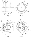
- Fig. 1 is a supply air wall duct 1 according to the invention, with a channel 2 with an outer side end 21 and an inner side end 22 for installation in a wall to be carried through (not shown, see Fig. 13 ff).
- the channel 2 is defined by an inside end portion 4, a middle portion 5, and partially by an outside end portion 3 of the supply air wall penetration formed.
- the middle section 5, in the example of this plastic, the adjacent parts of metal, causes a thermal decoupling of the outer side end portion 3 and the inner side end portion. 4
- two coupled flaps 31 and 32 are arranged in the supply air path arranged one behind the other in the outer side end portion 3, by means of which the channel 2 can be closed for the supply air.
- the flaps 31 and 32 are circular and pivotable on a mounted on the outer side end portion 3 of the channel pivot axis 33, 34.
- the flaps 31 and 32 At its end facing the wall of the channel, the flaps 31 and 32 have formed an elastic seal 73 and 74.
- Fig. 1 is the state with closed flaps shown in Fig. 2 with opened flaps.
- an actuating device 6 is arranged in the inner-side end section 4, protrudes through the outer side 41 of the tube extension piece 42 (see FIG Fig. 11 ff), wherein the actuator 6 is mechanically coupled to the flap (s) (31, 32) or blade (s).
- the mechanical coupling is effected by a purpose provided by the central portion 5 reaching linkage 61 and 62, by the actuator 6 and its axis 38 to the linkage control 39 and the symmetrically formed Linkage 61, 62 acts.
- the linkage 61, 62 in turn sets at two spaced apart from the pivot axis 33, 34 of the flaps 31, 32 located on the flap points 35, 36 and tilted about the pivot axis 33, 34th
- a simple stop 37 is provided, which is fixed to the channel wall.
- the channel ends at a stop plate 44, which terminates with the inside of the wall.
- a pipe extension piece 42 which projects beyond the stipulatemauernden part of the inner side end portion 4 for connecting a supply air stovepipe.
- the Fig. 3 to 6 show the representation after Fig. 1 from different angles.
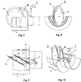
- FIGS. 11 and 12 the supply air wall bushing 1 according to the invention is shown with a channel extension 23 extending the channel 2 with a grille attachment adjoining thereto. Through the grille attachment 24, the outside air sucked on.
- Fig. 12 is still the arrangement after Fig. 11 shown in parts.
- the grille attachment 24 is shown disassembled in the parts front grille 24a, fine mesh 24b and aperture 24c.
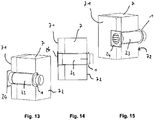
- Fig. 13 to 15 show the supply air wall bushing 1 according to the invention with channel extension 23 and grid attachment 24 in the installed state in a wall 7 in schematic sectional views in three different views.
- FIGS. 16 and 17 show the supply air duct wall 1 with the Aufschiebe Georgia 43 (see also, for example Fig. 1 . 2 . 11 ) of the pipe extension 42 connected Zu Kunststoff-stovepipe 81, which is connected to a stove 8.
- the supply air stovepipe in Fig. 17 omitted.
- the Fig. 18 shows a variant of the storage of the connected by the channel to the - closed in the example - flaps (only 32 visible) reaching linkage 61, 62 connected to axis 38, in the example shown, the actuator 6 is connected, wherein the axis 38 in a mounted on the wall 4a of the inner side end portion 4 (or its tube end piece 42) of the channel 2 axle bearing 38a is mounted so that the wall 4a of the lower portion inner side end portion 4 under no circumstances allows a condensate discharge into a room interior ,
Landscapes
- Engineering & Computer Science (AREA)
- General Engineering & Computer Science (AREA)
- Mechanical Engineering (AREA)
- Chemical & Material Sciences (AREA)
- Combustion & Propulsion (AREA)
- Air-Flow Control Members (AREA)
- Ventilation (AREA)
- Duct Arrangements (AREA)
- Specific Sealing Or Ventilating Devices For Doors And Windows (AREA)
Applications Claiming Priority (1)
| Application Number | Priority Date | Filing Date | Title |
|---|---|---|---|
| DE102011011772.5A DE102011011772B4 (de) | 2011-02-18 | 2011-02-18 | Zuluft-Wanddurchführung |
Publications (3)
| Publication Number | Publication Date |
|---|---|
| EP2489914A2 true EP2489914A2 (fr) | 2012-08-22 |
| EP2489914A3 EP2489914A3 (fr) | 2014-08-20 |
| EP2489914B1 EP2489914B1 (fr) | 2015-11-25 |
Family
ID=45655108
Family Applications (1)
| Application Number | Title | Priority Date | Filing Date |
|---|---|---|---|
| EP12001089.7A Active EP2489914B1 (fr) | 2011-02-18 | 2012-02-17 | Traversée de mur pour arrivée d'air |
Country Status (2)
| Country | Link |
|---|---|
| EP (1) | EP2489914B1 (fr) |
| DE (2) | DE102011011772B4 (fr) |
Cited By (3)
| Publication number | Priority date | Publication date | Assignee | Title |
|---|---|---|---|---|
| CN103969050A (zh) * | 2014-04-24 | 2014-08-06 | 中国北方发动机研究所(天津) | 一种单缸机背压调节装置 |
| CN104736940A (zh) * | 2012-08-25 | 2015-06-24 | Cb-Tec有限公司 | 供气墙体管道 |
| CN105351537A (zh) * | 2015-11-19 | 2016-02-24 | 成都九十度工业产品设计有限公司 | 一种双阀瓣蝶阀 |
Families Citing this family (1)
| Publication number | Priority date | Publication date | Assignee | Title |
|---|---|---|---|---|
| DE102015104520B4 (de) * | 2015-03-25 | 2025-02-27 | Naber Holding Gmbh & Co. Kg | Anordnung für die Volumenstromregulierung in einem Fluidkanal |
Family Cites Families (8)
| Publication number | Priority date | Publication date | Assignee | Title |
|---|---|---|---|---|
| FI43001B (fr) * | 1966-08-25 | 1970-09-02 | Noboe Fab As | |
| DE3207632A1 (de) * | 1982-02-26 | 1983-09-15 | Andreas 1000 Berlin Will | "absperrvorrichtung fuer rohrleitungen" |
| US5238220A (en) * | 1990-08-02 | 1993-08-24 | The Boeing Company | Manually and electrically controlled butterfly valve |
| DE69632714T2 (de) * | 1995-12-21 | 2005-06-30 | Valeo Climate Control Inc., Rochester Hills | Schalthebel |
| AT7509U1 (de) * | 2003-03-14 | 2005-04-25 | Johann Wernig Kg Kunststoff Un | Wartungsfreies brandschutzelement für lüftungsleitungen |
| AT500632B8 (de) * | 2004-07-22 | 2007-02-15 | Kamleithner Maly Uta Mag Ing | Brandschutzeinsatz |
| DE202006006327U1 (de) * | 2006-04-19 | 2006-08-24 | Berbel Ablufttechnik Gmbh | Mauerkasten |
| DE102007040632A1 (de) * | 2007-08-27 | 2009-03-05 | Özpolat, Ilgas, Dipl.-Ing. | Mauerkasten |
-
2011
- 2011-02-18 DE DE102011011772.5A patent/DE102011011772B4/de not_active Expired - Fee Related
-
2012
- 2012-02-17 EP EP12001089.7A patent/EP2489914B1/fr active Active
- 2012-02-17 DE DE201220013061 patent/DE202012013061U1/de not_active Expired - Lifetime
Cited By (3)
| Publication number | Priority date | Publication date | Assignee | Title |
|---|---|---|---|---|
| CN104736940A (zh) * | 2012-08-25 | 2015-06-24 | Cb-Tec有限公司 | 供气墙体管道 |
| CN103969050A (zh) * | 2014-04-24 | 2014-08-06 | 中国北方发动机研究所(天津) | 一种单缸机背压调节装置 |
| CN105351537A (zh) * | 2015-11-19 | 2016-02-24 | 成都九十度工业产品设计有限公司 | 一种双阀瓣蝶阀 |
Also Published As
| Publication number | Publication date |
|---|---|
| EP2489914B1 (fr) | 2015-11-25 |
| EP2489914A3 (fr) | 2014-08-20 |
| DE102011011772A1 (de) | 2012-08-23 |
| DE102011011772B4 (de) | 2015-02-05 |
| DE202012013061U1 (de) | 2015-02-23 |
Similar Documents
| Publication | Publication Date | Title |
|---|---|---|
| DE3540729C2 (fr) | ||
| EP2489914B1 (fr) | Traversée de mur pour arrivée d'air | |
| DE202009002307U1 (de) | Heizkörper mit Lüfterbaugruppe | |
| DE202010002960U1 (de) | Zuluftkamin für Nutztierställe | |
| EP2700885B1 (fr) | Passage de mur pour arrivée d'air | |
| EP2365248B1 (fr) | Cheminée de fumées pour installations de chauffage et tuyau de cheminée pour une telle cheminée | |
| DE10134839A1 (de) | Einrichtung zum rauch- und feuerbeständigen Verschliessen eines Wand- oder Deckendurchbruchs | |
| DE112010003695B4 (de) | Absperrvorrichtung für eine lüftungsdurchbrechung in einer gebäudewand | |
| EP1902258B1 (fr) | Caisson de guidage d'air | |
| EP2487424B1 (fr) | Hotte aspirante pour un four, une plaque de cuisson ou analogue | |
| DE102013114085A1 (de) | Lüftungsgerät zur Raumlüftung | |
| DE102011000525A1 (de) | Verfahren zum Betreiben einer Lüftungsanlage mit einer Mischkammer | |
| DE202008017906U1 (de) | Leitflächenlüfter für ein Dach eines Gebäudes | |
| EP2570742A1 (fr) | Canal d'aération pour l'encastrement dans une paroi | |
| EP1561996B1 (fr) | Dispositif de fermeture pour un tuyau conduisant un gas | |
| EP2241807A1 (fr) | Séparateur de particules de fumée | |
| EP0180914B1 (fr) | Clapet d'étranglement pour dispositifs de climatisation | |
| DE102013218418A1 (de) | Lüftungssystem, insbesondere Schnellinstallations-Lüftungssystem mit einem konfektionierbaren Durchführungselement | |
| DE102010056392B4 (de) | Einseitig schwenkbar gelagerte Brandschutzklappe mit verbesserter Dichtungswirkung | |
| DE102013107382A1 (de) | Haubeneinheit für Fahrzeug | |
| DE102010028740A1 (de) | Ab- und Zuluftmauerkasten | |
| DE19610884A1 (de) | Belüftungssystem für die Räume von Gebäuden | |
| DE102004059540B3 (de) | Vorrichtung zum Drosseln und Steuern von Strömungswegen, insbesondere in einem Schalldämpfer | |
| DE102017105750B4 (de) | Kastenkörper zur Aufnahme einer Verdunklungseinrichtung mit einer Belüftungsleitung | |
| DE202016103459U1 (de) | Lüftungsvorrichtung zur Lüftung von Gebäuderäumen |
Legal Events
| Date | Code | Title | Description |
|---|---|---|---|
| REG | Reference to a national code |
Ref country code: DE Ref legal event code: R138 Ref document number: 502012005311 Country of ref document: DE Free format text: GERMAN DOCUMENT NUMBER IS 502012005311 Ref country code: DE Ref legal event code: R138 Ref document number: 202012013061 Country of ref document: DE Free format text: GERMAN DOCUMENT NUMBER IS 502012005311 |
|
| PUAI | Public reference made under article 153(3) epc to a published international application that has entered the european phase |
Free format text: ORIGINAL CODE: 0009012 |
|
| AK | Designated contracting states |
Kind code of ref document: A2 Designated state(s): AL AT BE BG CH CY CZ DE DK EE ES FI FR GB GR HR HU IE IS IT LI LT LU LV MC MK MT NL NO PL PT RO RS SE SI SK SM TR |
|
| AX | Request for extension of the european patent |
Extension state: BA ME |
|
| PUAL | Search report despatched |
Free format text: ORIGINAL CODE: 0009013 |
|
| AK | Designated contracting states |
Kind code of ref document: A3 Designated state(s): AL AT BE BG CH CY CZ DE DK EE ES FI FR GB GR HR HU IE IS IT LI LT LU LV MC MK MT NL NO PL PT RO RS SE SI SK SM TR |
|
| AX | Request for extension of the european patent |
Extension state: BA ME |
|
| RIC1 | Information provided on ipc code assigned before grant |
Ipc: F23L 3/00 20060101ALI20140715BHEP Ipc: F23L 13/02 20060101ALI20140715BHEP Ipc: F16L 5/12 20060101ALI20140715BHEP Ipc: F24F 13/14 20060101ALI20140715BHEP Ipc: F16K 1/22 20060101ALI20140715BHEP Ipc: F16L 25/00 20060101AFI20140715BHEP |
|
| 17P | Request for examination filed |
Effective date: 20150218 |
|
| RBV | Designated contracting states (corrected) |
Designated state(s): AL AT BE BG CH CY CZ DE DK EE ES FI FR GB GR HR HU IE IS IT LI LT LU LV MC MK MT NL NO PL PT RO RS SE SI SK SM TR |
|
| GRAP | Despatch of communication of intention to grant a patent |
Free format text: ORIGINAL CODE: EPIDOSNIGR1 |
|
| INTG | Intention to grant announced |
Effective date: 20150623 |
|
| GRAS | Grant fee paid |
Free format text: ORIGINAL CODE: EPIDOSNIGR3 |
|
| GRAA | (expected) grant |
Free format text: ORIGINAL CODE: 0009210 |
|
| AK | Designated contracting states |
Kind code of ref document: B1 Designated state(s): AL AT BE BG CH CY CZ DE DK EE ES FI FR GB GR HR HU IE IS IT LI LT LU LV MC MK MT NL NO PL PT RO RS SE SI SK SM TR |
|
| REG | Reference to a national code |
Ref country code: GB Ref legal event code: FG4D Free format text: NOT ENGLISH |
|
| REG | Reference to a national code |
Ref country code: CH Ref legal event code: EP |
|
| REG | Reference to a national code |
Ref country code: AT Ref legal event code: REF Ref document number: 762802 Country of ref document: AT Kind code of ref document: T Effective date: 20151215 |
|
| REG | Reference to a national code |
Ref country code: IE Ref legal event code: FG4D Free format text: LANGUAGE OF EP DOCUMENT: GERMAN |
|
| REG | Reference to a national code |
Ref country code: DE Ref legal event code: R096 Ref document number: 502012005311 Country of ref document: DE |
|
| REG | Reference to a national code |
Ref country code: LT Ref legal event code: MG4D |
|
| REG | Reference to a national code |
Ref country code: NL Ref legal event code: MP Effective date: 20160225 |
|
| REG | Reference to a national code |
Ref country code: CH Ref legal event code: NV Representative=s name: MEYER AND KOLLEGEN, CH |
|
| PG25 | Lapsed in a contracting state [announced via postgrant information from national office to epo] |
Ref country code: HR Free format text: LAPSE BECAUSE OF FAILURE TO SUBMIT A TRANSLATION OF THE DESCRIPTION OR TO PAY THE FEE WITHIN THE PRESCRIBED TIME-LIMIT Effective date: 20151125 Ref country code: NL Free format text: LAPSE BECAUSE OF FAILURE TO SUBMIT A TRANSLATION OF THE DESCRIPTION OR TO PAY THE FEE WITHIN THE PRESCRIBED TIME-LIMIT Effective date: 20151125 Ref country code: ES Free format text: LAPSE BECAUSE OF FAILURE TO SUBMIT A TRANSLATION OF THE DESCRIPTION OR TO PAY THE FEE WITHIN THE PRESCRIBED TIME-LIMIT Effective date: 20151125 Ref country code: LT Free format text: LAPSE BECAUSE OF FAILURE TO SUBMIT A TRANSLATION OF THE DESCRIPTION OR TO PAY THE FEE WITHIN THE PRESCRIBED TIME-LIMIT Effective date: 20151125 Ref country code: IS Free format text: LAPSE BECAUSE OF FAILURE TO SUBMIT A TRANSLATION OF THE DESCRIPTION OR TO PAY THE FEE WITHIN THE PRESCRIBED TIME-LIMIT Effective date: 20160325 Ref country code: NO Free format text: LAPSE BECAUSE OF FAILURE TO SUBMIT A TRANSLATION OF THE DESCRIPTION OR TO PAY THE FEE WITHIN THE PRESCRIBED TIME-LIMIT Effective date: 20160225 |
|
| PG25 | Lapsed in a contracting state [announced via postgrant information from national office to epo] |
Ref country code: PT Free format text: LAPSE BECAUSE OF FAILURE TO SUBMIT A TRANSLATION OF THE DESCRIPTION OR TO PAY THE FEE WITHIN THE PRESCRIBED TIME-LIMIT Effective date: 20160325 Ref country code: LV Free format text: LAPSE BECAUSE OF FAILURE TO SUBMIT A TRANSLATION OF THE DESCRIPTION OR TO PAY THE FEE WITHIN THE PRESCRIBED TIME-LIMIT Effective date: 20151125 Ref country code: BE Free format text: LAPSE BECAUSE OF NON-PAYMENT OF DUE FEES Effective date: 20160229 Ref country code: FI Free format text: LAPSE BECAUSE OF FAILURE TO SUBMIT A TRANSLATION OF THE DESCRIPTION OR TO PAY THE FEE WITHIN THE PRESCRIBED TIME-LIMIT Effective date: 20151125 Ref country code: RS Free format text: LAPSE BECAUSE OF FAILURE TO SUBMIT A TRANSLATION OF THE DESCRIPTION OR TO PAY THE FEE WITHIN THE PRESCRIBED TIME-LIMIT Effective date: 20151125 Ref country code: PL Free format text: LAPSE BECAUSE OF FAILURE TO SUBMIT A TRANSLATION OF THE DESCRIPTION OR TO PAY THE FEE WITHIN THE PRESCRIBED TIME-LIMIT Effective date: 20151125 Ref country code: SE Free format text: LAPSE BECAUSE OF FAILURE TO SUBMIT A TRANSLATION OF THE DESCRIPTION OR TO PAY THE FEE WITHIN THE PRESCRIBED TIME-LIMIT Effective date: 20151125 Ref country code: GR Free format text: LAPSE BECAUSE OF FAILURE TO SUBMIT A TRANSLATION OF THE DESCRIPTION OR TO PAY THE FEE WITHIN THE PRESCRIBED TIME-LIMIT Effective date: 20160226 |
|
| PG25 | Lapsed in a contracting state [announced via postgrant information from national office to epo] |
Ref country code: CZ Free format text: LAPSE BECAUSE OF FAILURE TO SUBMIT A TRANSLATION OF THE DESCRIPTION OR TO PAY THE FEE WITHIN THE PRESCRIBED TIME-LIMIT Effective date: 20151125 Ref country code: IT Free format text: LAPSE BECAUSE OF FAILURE TO SUBMIT A TRANSLATION OF THE DESCRIPTION OR TO PAY THE FEE WITHIN THE PRESCRIBED TIME-LIMIT Effective date: 20151125 |
|
| REG | Reference to a national code |
Ref country code: DE Ref legal event code: R097 Ref document number: 502012005311 Country of ref document: DE |
|
| PG25 | Lapsed in a contracting state [announced via postgrant information from national office to epo] |
Ref country code: RO Free format text: LAPSE BECAUSE OF FAILURE TO SUBMIT A TRANSLATION OF THE DESCRIPTION OR TO PAY THE FEE WITHIN THE PRESCRIBED TIME-LIMIT Effective date: 20151125 Ref country code: SK Free format text: LAPSE BECAUSE OF FAILURE TO SUBMIT A TRANSLATION OF THE DESCRIPTION OR TO PAY THE FEE WITHIN THE PRESCRIBED TIME-LIMIT Effective date: 20151125 Ref country code: DK Free format text: LAPSE BECAUSE OF FAILURE TO SUBMIT A TRANSLATION OF THE DESCRIPTION OR TO PAY THE FEE WITHIN THE PRESCRIBED TIME-LIMIT Effective date: 20151125 Ref country code: EE Free format text: LAPSE BECAUSE OF FAILURE TO SUBMIT A TRANSLATION OF THE DESCRIPTION OR TO PAY THE FEE WITHIN THE PRESCRIBED TIME-LIMIT Effective date: 20151125 Ref country code: SM Free format text: LAPSE BECAUSE OF FAILURE TO SUBMIT A TRANSLATION OF THE DESCRIPTION OR TO PAY THE FEE WITHIN THE PRESCRIBED TIME-LIMIT Effective date: 20151125 |
|
| PG25 | Lapsed in a contracting state [announced via postgrant information from national office to epo] |
Ref country code: LU Free format text: LAPSE BECAUSE OF FAILURE TO SUBMIT A TRANSLATION OF THE DESCRIPTION OR TO PAY THE FEE WITHIN THE PRESCRIBED TIME-LIMIT Effective date: 20160217 Ref country code: MC Free format text: LAPSE BECAUSE OF FAILURE TO SUBMIT A TRANSLATION OF THE DESCRIPTION OR TO PAY THE FEE WITHIN THE PRESCRIBED TIME-LIMIT Effective date: 20151125 |
|
| PLBE | No opposition filed within time limit |
Free format text: ORIGINAL CODE: 0009261 |
|
| STAA | Information on the status of an ep patent application or granted ep patent |
Free format text: STATUS: NO OPPOSITION FILED WITHIN TIME LIMIT |
|
| GBPC | Gb: european patent ceased through non-payment of renewal fee |
Effective date: 20160225 |
|
| 26N | No opposition filed |
Effective date: 20160826 |
|
| REG | Reference to a national code |
Ref country code: FR Ref legal event code: ST Effective date: 20161028 |
|
| PG25 | Lapsed in a contracting state [announced via postgrant information from national office to epo] |
Ref country code: SI Free format text: LAPSE BECAUSE OF FAILURE TO SUBMIT A TRANSLATION OF THE DESCRIPTION OR TO PAY THE FEE WITHIN THE PRESCRIBED TIME-LIMIT Effective date: 20151125 |
|
| REG | Reference to a national code |
Ref country code: IE Ref legal event code: MM4A |
|
| PG25 | Lapsed in a contracting state [announced via postgrant information from national office to epo] |
Ref country code: FR Free format text: LAPSE BECAUSE OF NON-PAYMENT OF DUE FEES Effective date: 20160229 Ref country code: IE Free format text: LAPSE BECAUSE OF NON-PAYMENT OF DUE FEES Effective date: 20160217 Ref country code: GB Free format text: LAPSE BECAUSE OF NON-PAYMENT OF DUE FEES Effective date: 20160225 |
|
| PG25 | Lapsed in a contracting state [announced via postgrant information from national office to epo] |
Ref country code: MT Free format text: LAPSE BECAUSE OF FAILURE TO SUBMIT A TRANSLATION OF THE DESCRIPTION OR TO PAY THE FEE WITHIN THE PRESCRIBED TIME-LIMIT Effective date: 20151125 |
|
| REG | Reference to a national code |
Ref country code: DE Ref legal event code: R082 Ref document number: 502012005311 Country of ref document: DE Representative=s name: PATENTANWALTSKANZLEI MEYER, DE Ref country code: DE Ref legal event code: R081 Ref document number: 502012005311 Country of ref document: DE Owner name: CB-TEC GMBH, DE Free format text: FORMER OWNER: CB-TEC GMBH, 87789 WORINGEN, DE |
|
| REG | Reference to a national code |
Ref country code: CH Ref legal event code: PCOW Free format text: NEW ADDRESS: BEHAIMWEG 2, 87781 UNGERHAUSEN (DE) |
|
| PG25 | Lapsed in a contracting state [announced via postgrant information from national office to epo] |
Ref country code: HU Free format text: LAPSE BECAUSE OF FAILURE TO SUBMIT A TRANSLATION OF THE DESCRIPTION OR TO PAY THE FEE WITHIN THE PRESCRIBED TIME-LIMIT; INVALID AB INITIO Effective date: 20120217 Ref country code: CY Free format text: LAPSE BECAUSE OF FAILURE TO SUBMIT A TRANSLATION OF THE DESCRIPTION OR TO PAY THE FEE WITHIN THE PRESCRIBED TIME-LIMIT Effective date: 20151125 |
|
| PGFP | Annual fee paid to national office [announced via postgrant information from national office to epo] |
Ref country code: AT Payment date: 20180105 Year of fee payment: 7 |
|
| PG25 | Lapsed in a contracting state [announced via postgrant information from national office to epo] |
Ref country code: MK Free format text: LAPSE BECAUSE OF FAILURE TO SUBMIT A TRANSLATION OF THE DESCRIPTION OR TO PAY THE FEE WITHIN THE PRESCRIBED TIME-LIMIT Effective date: 20151125 Ref country code: TR Free format text: LAPSE BECAUSE OF FAILURE TO SUBMIT A TRANSLATION OF THE DESCRIPTION OR TO PAY THE FEE WITHIN THE PRESCRIBED TIME-LIMIT Effective date: 20151125 |
|
| PG25 | Lapsed in a contracting state [announced via postgrant information from national office to epo] |
Ref country code: BG Free format text: LAPSE BECAUSE OF FAILURE TO SUBMIT A TRANSLATION OF THE DESCRIPTION OR TO PAY THE FEE WITHIN THE PRESCRIBED TIME-LIMIT Effective date: 20151125 |
|
| PG25 | Lapsed in a contracting state [announced via postgrant information from national office to epo] |
Ref country code: AL Free format text: LAPSE BECAUSE OF FAILURE TO SUBMIT A TRANSLATION OF THE DESCRIPTION OR TO PAY THE FEE WITHIN THE PRESCRIBED TIME-LIMIT Effective date: 20151125 |
|
| REG | Reference to a national code |
Ref country code: AT Ref legal event code: MM01 Ref document number: 762802 Country of ref document: AT Kind code of ref document: T Effective date: 20190217 |
|
| PG25 | Lapsed in a contracting state [announced via postgrant information from national office to epo] |
Ref country code: AT Free format text: LAPSE BECAUSE OF NON-PAYMENT OF DUE FEES Effective date: 20190217 |
|
| PGFP | Annual fee paid to national office [announced via postgrant information from national office to epo] |
Ref country code: CH Payment date: 20250301 Year of fee payment: 14 |
|
| PGFP | Annual fee paid to national office [announced via postgrant information from national office to epo] |
Ref country code: DE Payment date: 20251228 Year of fee payment: 15 |