EP2489952B2 - Chauffe-eau instantané électrique - Google Patents
Chauffe-eau instantané électrique Download PDFInfo
- Publication number
- EP2489952B2 EP2489952B2 EP11155220.4A EP11155220A EP2489952B2 EP 2489952 B2 EP2489952 B2 EP 2489952B2 EP 11155220 A EP11155220 A EP 11155220A EP 2489952 B2 EP2489952 B2 EP 2489952B2
- Authority
- EP
- European Patent Office
- Prior art keywords
- channel
- arrangement
- base body
- channels
- height
- Prior art date
- Legal status (The legal status is an assumption and is not a legal conclusion. Google has not performed a legal analysis and makes no representation as to the accuracy of the status listed.)
- Active
Links
Images




Classifications
-
- F—MECHANICAL ENGINEERING; LIGHTING; HEATING; WEAPONS; BLASTING
- F24—HEATING; RANGES; VENTILATING
- F24H—FLUID HEATERS, e.g. WATER OR AIR HEATERS, HAVING HEAT-GENERATING MEANS, e.g. HEAT PUMPS, IN GENERAL
- F24H1/00—Water heaters, e.g. boilers, continuous-flow heaters or water-storage heaters
- F24H1/10—Continuous-flow heaters, i.e. heaters in which heat is generated only while the water is flowing, e.g. with direct contact of the water with the heating medium
- F24H1/101—Continuous-flow heaters, i.e. heaters in which heat is generated only while the water is flowing, e.g. with direct contact of the water with the heating medium using electric energy supply
- F24H1/102—Continuous-flow heaters, i.e. heaters in which heat is generated only while the water is flowing, e.g. with direct contact of the water with the heating medium using electric energy supply with resistance
- F24H1/103—Continuous-flow heaters, i.e. heaters in which heat is generated only while the water is flowing, e.g. with direct contact of the water with the heating medium using electric energy supply with resistance with bare resistances in direct contact with the fluid
-
- F—MECHANICAL ENGINEERING; LIGHTING; HEATING; WEAPONS; BLASTING
- F24—HEATING; RANGES; VENTILATING
- F24H—FLUID HEATERS, e.g. WATER OR AIR HEATERS, HAVING HEAT-GENERATING MEANS, e.g. HEAT PUMPS, IN GENERAL
- F24H1/00—Water heaters, e.g. boilers, continuous-flow heaters or water-storage heaters
- F24H1/10—Continuous-flow heaters, i.e. heaters in which heat is generated only while the water is flowing, e.g. with direct contact of the water with the heating medium
- F24H1/12—Continuous-flow heaters, i.e. heaters in which heat is generated only while the water is flowing, e.g. with direct contact of the water with the heating medium in which the water is kept separate from the heating medium
- F24H1/14—Continuous-flow heaters, i.e. heaters in which heat is generated only while the water is flowing, e.g. with direct contact of the water with the heating medium in which the water is kept separate from the heating medium by tubes, e.g. bent in serpentine form
- F24H1/142—Continuous-flow heaters, i.e. heaters in which heat is generated only while the water is flowing, e.g. with direct contact of the water with the heating medium in which the water is kept separate from the heating medium by tubes, e.g. bent in serpentine form using electric energy supply
-
- F—MECHANICAL ENGINEERING; LIGHTING; HEATING; WEAPONS; BLASTING
- F24—HEATING; RANGES; VENTILATING
- F24H—FLUID HEATERS, e.g. WATER OR AIR HEATERS, HAVING HEAT-GENERATING MEANS, e.g. HEAT PUMPS, IN GENERAL
- F24H9/00—Details
- F24H9/02—Casings; Cover lids; Ornamental panels
-
- F—MECHANICAL ENGINEERING; LIGHTING; HEATING; WEAPONS; BLASTING
- F24—HEATING; RANGES; VENTILATING
- F24H—FLUID HEATERS, e.g. WATER OR AIR HEATERS, HAVING HEAT-GENERATING MEANS, e.g. HEAT PUMPS, IN GENERAL
- F24H9/00—Details
- F24H9/14—Arrangements for connecting different sections, e.g. in water heaters
- F24H9/146—Connecting elements of a heat exchanger
-
- F—MECHANICAL ENGINEERING; LIGHTING; HEATING; WEAPONS; BLASTING
- F24—HEATING; RANGES; VENTILATING
- F24H—FLUID HEATERS, e.g. WATER OR AIR HEATERS, HAVING HEAT-GENERATING MEANS, e.g. HEAT PUMPS, IN GENERAL
- F24H9/00—Details
- F24H9/18—Arrangement or mounting of grates or heating means
- F24H9/1809—Arrangement or mounting of grates or heating means for water heaters
- F24H9/1818—Arrangement or mounting of electric heating means
Definitions
- the invention relates to an electric instantaneous water heater, comprising a base body extending in the longitudinal, width and height dimensions with a front and a rear, the rear separating a rear wet area from a front drying room, comprising an electric heating device which is attached to the inside of the drying room
- the front side of the base body is arranged, comprising a channel arrangement formed in the base body which comprises several water channels set up for the passage of water to be heated and heated, which extend as longitudinal channels in the longitudinal dimension and in width and height positions on the base body through an arrangement profile cross-section directed transversely to the channel extension are determined in the width dimension of the base body channel layers of channels lying next to one another in a row with close packing, namely channel width layers, as well as in the height dimension of the base body channel layers in series closely packed adjacent channels, namely channel elevation layers, wherein a deflection face corresponding to the arrangement profile cross-section is formed on a broad side of the base body, which is designed to divert the water passage between channel openings, with which adjacent channels
- Known electrical instantaneous water heaters of the type mentioned have a base body which, as is preferably also the case with the subject matter of the invention, is designed monolithically in its entirety, being manufactured, for example, as a plastic injection-molded part that has sufficient strength and electrical insulating properties.
- The, in particular, monolithic base body forms a one-piece assembly body on which the front side, namely in the dry space between its front or inner side located in the water heater and an outer housing, e.g. a hood, components of an electrical heating device are mounted or arranged.
- Such components include, for example, electrical circuit boards and their assembly, in particular with electronic power switching elements, for example triacs, transformers and capacitors.
- the base body of the generic instantaneous water heater is open on two broad sides, each on an edge surface of a monolithic area of the base body, which has openings and is intended to deflect the waterway, namely in the deflection face with water channels.
- the deflection end faces and the cover parts are joined together in a watertight and pressure-tight manner. Sealed bridge channels are formed between the cover parts and the deflection end faces, which connect adjacent or mutually associated channel openings.
- the base body mostly extends longer in the longitudinal dimension than in the width dimension, the length ratio can be reversed in the two dimensions or the lengths can be at least substantially the same.
- the base body is usually a cuboid structure. It can also be at least partially free of corners and thus round.
- the body front side of the base body is always to be understood as the side facing the drying room and the back side of the body as the side facing away from the drying room, regardless of the designation, orientation and / or arrangement of the side of the water heater or its housing.
- the water-carrying channels are part of the preferably completely monolithic base body.
- the area forming the channel arrangement can, however, also be divided into, for example, two monolithic parts of the base body.
- Known electrical water heaters of the type mentioned have a base body forming a monolithic central part with two end faces forming broad sides, on each of which a cover part is attached in a butt seat over the entire surface of the broad side.
- the channel arrangement of such instantaneous water heaters is formed over the entire width, length and height of the base body.
- water-conducting channels which are provided essentially free of elements for guiding water that engage in them, are arranged in two layers one above the other.
- additional water channels with relatively large cross-sections, into which heating coils are inserted are arranged in a third layer.
- the main body with the large-scale channel system integrated over its entire width dimension and the corresponding one Channel arrangement as relatively voluminous, its rear side and its front side can only be used to a limited extent for the arrangement of components, namely with a special overall height in addition to the height of the channel arrangement.
- the objectives of the invention are to improve the generic instantaneous water heater with regard to the simple construction, the sealing property between the deflection end face and the cover part, and a compact design and yet space-saving arrangement of components on the base body.
- the manufacture and handling of the base body as an injection-molded part made of plastic should also be improved.
- the aims of the invention are achieved by the features of claim 1 in conjunction with the features of the electrical water heater mentioned at the outset.
- the spatial area of the channel arrangement is concentrated and limited to only a part of the base body, which is preferably entirely monolithic.
- the channels of the channel arrangement are preferably exclusive water channels which, as such, do not accommodate any other components that increase the cross-section, in particular no heating wires.
- body-free height is obtained in the area or areas of the base body, which forms installation space with a corresponding installation depth.
- the area free from the duct arrangement essentially comprises only at least one flat body wall, on whose side facing the drying room adjoining it and / or carried by it, components of the heating device, in particular voluminous parts such as transformers and capacitors, are received.
- the base body in addition to the channel arrangement free from this, recessed relative to their height, which are expediently equipped with the body wall mentioned as a mounting mounting platform.
- the space obtained in this way and free from the duct arrangement can, in particular lying next to one another in the longitudinal dimension and / or height dimension, be divided into spaces, preferably separated into receiving compartments. Savings are also achieved in terms of the space required for the base area of the flow heater.
- the concentration of Channel arrangement in a height range of the base body the entire base area of the base body, while maintaining or even expanding the electrical equipment of the device, is smaller in comparison with conventional base bodies.
- the effective sealing surface is limited to the area of a circular surface within which the geometry of the deflection end face or the corresponding sealing surface formed thereby is uniform in terms of width and height.
- Such a sealing surface can be sealed with reduced clamping force compared to a sealing surface that is conventionally long, so that the clamping means expenditure is also reduced and the clamping force is achieved particularly effectively with a few, for example only four, fastening points on the circumference of the sealing / deflection face .
- the compression of the sealing / deflection end face according to the invention also reduces the disadvantageous effects of production-related deformations of the base body made of plastic, which is produced in the injection molding process. This means that the warpage of plastic parts is reduced and the sealing effect is improved.
- the advantages of the invention are particularly evident when the base body in its entirety is a monolithic body made of plastic.
- the design with already three channel height layers allows the construction depth of the second base body part in the height range corresponding to the height of the channel arrangement to be equal to the height of at least one and a half channel height layers and preferably equal to the height of at least two channel height layers.
- the installation space limited by the body wall also on the rear side of the second base body component can be formed with a depth that is equal to the height of at least one and a half channel height layers.
- the deflection end face is particularly advantageously given a shape that can be compactly inserted into the imaginary circular geometry mentioned, in such a way that the deflection end face is delimited by an annular circumferential surface edge which surrounds the entirety of the channel openings, the deflection end face having a geometric surface shape delimited by the surface edge , which corresponds at least approximately to a surface shape that belongs to the group of surface basic shapes that are circular, oval, trapezoidal, square and rhombus-shaped.
- a basic surface shape can be defined in that two normal axes of the surface shape, which are at right angles to one another, are central axes with half-lengths spanning the surface shape.
- the correspondence ratio of the lengths of the two normal axes of the surface shape mentioned is advantageously chosen to be not less than 50% and preferably not less than 55%.
- a recessed arrangement of the cover part has proven to be particularly advantageous in connection with the compact channel arrangement and the corresponding deflection face.
- a surface edge delimiting the deflection end face is designed as a collar edge, which forms a receptacle which receives the cover part and advantageously also fastening elements without protrusion.
- Fastening points are advantageously arranged on the deflection end face delimited by means of a surface edge or sunk by a collar edge, in particular as corner points or points of the surface edge.
- the arrangement profile cross-sections of the channels can be represented and determined with a geometric arrangement matrix comprising matrix fields.
- the matrix fields define possible positions of the channels.
- the arrangement matrix has the number of N arrangement rows and the number of n arrangement columns, which are preferably in the height dimension.
- the rows or columns can have different widths. This means that in a row or column and / or in different rows or columns, the channels have different cross-sections and / or are also offset from one another so that the duct openings in a row or column do not necessarily align with one another.
- Such designs of the channel arrangement are independent of the arrangement matrix mentioned.
- the rows or columns can be at an angle to the margins.
- the arrangement matrix defines a group of possible arrangement areas for a maximum of N x n channels with, of course, number N ⁇ 3 and N-1 ⁇ n N + 4. Thereafter, the smallest arrangement areas are for a maximum of N x (N-1) channels and largest arrangement areas defined for a maximum of N x (N + 4) channels.
- the number and arrangement of the channels are further determined by the fact that in an arrangement area selected from the group mentioned in at least one arrangement column in number N in series successive channels and also in each arrangement line and in each arrangement column at least one channel are arranged. As a result, a channel pattern is determined in the profile cross-section of the arrangement.
- a channel arrangement approximating in particular a square or square surface shape can be formed by a central arrangement of K x K channels with, of course, the number K ⁇ 3, each with K channel height positions and K channel width positions.
- Surface forms or areas deviating from the K x K channel arrangement can also be defined in that the central arrangement is surrounded by at least one further channel adjoining it, which the central arrangement in at least one of two dimensions, namely in the width dimension and height dimension of the first Basic body part, supplemented by a maximum of one channel each side of the central arrangement.
- Said central arrangement can also be surrounded by at least one group of channels adjoining it, which supplements the central arrangement in the direction of at least one of two dimensions, namely the width dimension and height dimension of the first main body part, by a maximum of two channel layers each to the side of the central arrangement.
- Arrangements can be designed in such a way that the channels surrounding the central arrangement are arranged diagonally opposite one another in relation to the central arrangement.
- the first base body part has, for example, a width dimension that is approximately one-half to two-thirds the width dimension of the base body.
- the channel arrangement of the longitudinal channels can, although it is formed only in part of the base body, be connected to the inlet channel and outlet channel directed transversely, in particular perpendicular to the longitudinal channels, which extend in an area of the base body free from the channel arrangement.
- the channel arrangement can comprise an outer channel which is divided at a separation point into two sub-channels adjoining one another in series, the first sub-channel forming an inlet channel and the second sub-channel forming an outlet channel in the channel arrangement, each for connection to a water line in the area of the Separation point with an external opening are open.
- each duct is connected at its end through the associated outer opening to the associated sub-duct and at its other end to the external connection is provided on a water pipe.
- the flow heater according to the invention is not limited to an embodiment with a bare wire heating device
- the duct arrangement according to the invention is particularly advantageously provided in a flow heater with a heating device which comprises at least one heating element, which is set up with at least one bare wire arranged in the water, on the base body arranged and connected between water channels forming electrical water resistance paths.
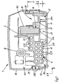
- An electric instantaneous water heater 1 shown in the figures comprises a hood 12, a frame-shaped housing back part 13 and a monolithic base body 2 with a body front 201, body back 202 and circumferential body edge 200.
- the basic shape of the instantaneous water heater 1 is essentially cuboid.
- the basic shape of the base body 2 is cuboid with mutually opposite longitudinal sides and broad sides forming the edge side 200.
- the long sides and broad sides extend in longitudinal dimension L or width dimension B and the edge side 200 is in height dimension H.
- the base body is expediently a part molded from plastic.
- the base body 2 divides the water heater 1 into a drying room 101 and a wet room or wet area 102.
- the drying room 101 is the area covered by the hood 12, while the wet area is surrounded by the frame of the rear part 13 of the housing.
- the rear side 202 of the main body is an outer side.
- An electrical heating device for heating water flowing through is arranged on the inside or front side 201 of the base body 2.
- some components 15, namely in particular a flat circuit board 151, a circuit board 152, a transformer 153 and a capacitor 154 are shown.
- a bare wire heating cartridge 8 is also part of the heating device.
- the edge side 200 of the base body 2 is equipped all around with a web system which is fitted between the base body 2 and the hood 12.
- the bar system separates the drying room 101 from the wet area 202 in such a way that the passage of dripping water, splash water and / or water jets is blocked.
- the web system comprises sealing webs 280 formed on side walls 28 and on cover parts 3.
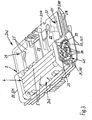
- the width of the monolithic base body 2 is divided into two base body parts 203, 204 which, as in particular from Fig. 1 , 3 and 4B appears to form two longitudinal halves of the base body 2.
- the first base body part 203 forms a part body protruding in height dimension H on the front side 201 and on the rear side 202, in which water channels 5 are formed in a special channel arrangement 4.
- the water channels 5 extend in the longitudinal dimension L parallel.
- the water channels 5 are open on the base body 2 on both broad sides in an end face with channel openings 51. This end face is referred to as the deflection end face 21, at which the channel openings 51 are connected to one another in a deflecting manner along the waterway of the channel arrangement 4.
- the water heater 1 further comprises the cover parts 3, which are formed by monolithic edge parts.
- Each deflection end face 21 has a cover part 3 with an inner surface 32 adapted to the deflection end face 21 and correspondingly delimiting the inside of the cover. That to the in Fig. 3
- the cover parts 3 are expediently injection-molded parts made of plastic.
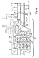
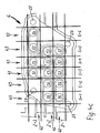
- Figure 4A , 4B and 4C show one broad side of the base body 2.
- the other broad side is designed with a corresponding basic shape of the corresponding deflection end face 21, as shown in FIG Fig. 3 can be seen.
- the water channels 5 of the channel arrangement 4 extend between the two deflection end faces 21, to which they are directed perpendicularly.
- the openings 51 of the water channels 5 are connected to form a waterway of the channel arrangement 4.
- Adjacent channel openings 51 or channel ends are connected to one another in pairs with vertical and horizontal channel pairs 511, 512, each via a bridge channel.
- Bridge channel halves 29 are formed in the deflection end face 21 and corresponding bridge channel halves 39 are formed in the cover part 3.
- each lid part 3 forms a sealing surface with the bridge channel halves 39.
- the deflection end surface 21 likewise forms a sealing surface with the sealing surface of the cover part 3 of a corresponding shape.
- the bridge channel halves 29, 39 come to lie against one another in a sealed manner.
- a watertight and pressure-tight seal can each have the half-shape of the channel halves 29, 39, 38 corresponding edge sealing rings, not shown, which can be components of a sealing mat, a sealing net or similar sealing elements, and between the base body 2 and the cover part 3 in grooves 24 , 34 are inserted horizontally.
- the second base body part 204 free from the channel arrangement 4 of the longitudinal channels is embodied with body walls 25 extending in the longitudinal and width dimensions L, B.
- Each body wall 25 leaves construction space 26, in particular in the form of receiving compartments, on the front side of the second base body part 204 facing the drying space 201.
- This installation space 26 or the receiving compartments are formed in the height dimension H next to the duct arrangement 4 and in this area have a maximum installation depth T for components 15 of the electrical heating device 8, in particular as shown in FIG Fig. 1 and 5 can be seen for transformers, capacitors and printed circuit boards. Not all such components are shown, and in particular in FIG Fig.
- the base body 2 is shown with the receiving compartments without components 15 received by them.
- the maximum overall depth T of the second base body part 204 in the height range corresponding to the height of the channel arrangement is approximately the height of two channel height layers 42 of the channel arrangement 4.
- the second base body part 204 also has body walls 25 which delimit the installation space 27 which is formed on the underside of the second base body part 204 next to the channel arrangement 4, namely next to the channel arrangement 4 with a maximum installation depth t, which is approximately equal to the height of approx one and a half duct elevations 42 is.
- the channel arrangement 4 protrudes both on the front side 201 and on the rear side 202 of the base body 2 to form the installation spaces 26, 27 mentioned.
- the arrangement of the water channels 5 has in the profile cross-section perpendicular to the channels, which is referred to below as the arrangement profile cross-section 41, in each case on the deflection end face 21, the deflection end face 21 forming a surface bounded by a surface edge 22 and having the channel openings 51 .
- the arrangement profile cross-section 41 is initially based on Figure 4C Described on a broad side of the base body 2.
- the arrangement profile cross-section 41 is determined there by an arrangement matrix 6 comprising matrix fields and by specific matrix fields occupied by water channels 5, so that a profile pattern of the channels 5 is defined.
- a tight packing is formed when the majority of the channels are arranged in adjacent matrix fields regardless of a distribution rule on the matrix fields.
- the arrangement matrix 6 determines a group of arrangement areas for a maximum of N xn channels with a natural number N ⁇ 3 and N-1 n N + 4, namely the smallest arrangement areas for a maximum of N x (N-1) channels and the largest arrangement areas for a maximum of N x (N + 4) channels.
- N 3
- the largest arrangement area is three matrix rows Z. and comprises seven matrix columns S, that is to say twenty-one matrix fields.
- channels 5 following one another in series are arranged in at least one arrangement column S according to the number N and in addition at least one channel is arranged in each arrangement line Z.
- the arrangement is further determined by the fact that it is surrounded by a further channel 54 adjoining it, which is the central arrangement 40 in the width dimension B supplemented by a channel on the side of the central arrangement.
- the channel 54 and the channels 56 of the channel group 401 are arranged diagonally opposite one another with respect to the central arrangement 40.
- the channel arrangement 4 or in Figure 4A , B, and C shown deflection face 21 due to the described channel arrangement 4 on a special trapezoidal surface shape 210.
- the trapezoidal surface shape 210 is determined at least essentially by straight polygon sections or lines of the surface edge 22 of the sealing deflection face 21.
- the surface edge 22 surrounds the entirety of the channels 5 or the channel openings 51 in an annular manner.
- Fastening points 23 are provided at four corner points of the polygonal sections in the area adjoining the channels 5. This means that in the exemplary embodiment, the essentially trapezoidal shape is formed between four fastening points 23 with two lines that are essentially parallel in width dimension B and with inclined, identically oriented sections in height dimension H.
- the parallel lines are one in length Normal axis 211 and the inclined sections with the length of a normal axis 212 spaced apart.
- These normal axes 211, 212 are defined as central axes which intersect at right angles and which form half-lengths spanning the trapezoidal surface shape 210.
- the ratio of the length of the normal axis 211 in the height dimension H and the normal axis 212 in the width dimension B is approximately 57%.
- the exemplary embodiment shows the trapezoidal shape 210 of the deflection end face 21 as an example.
- other surface shapes in which a compressed arrangement of the channels 5 is inscribed can be provided, for example surface shapes that are at least approximately circular, oval, square or rhombus-shaped.
- Such surface shapes, which are not shown, are also determined by two normal axes in accordance with the preceding description.
- the four fastening points 23 are equally or approximately equally distributed in relation to the height dimension H and the width dimension B.
- the surface edge 22 is designed as a collar edge 221, so that the deflection face 21 is sunk therein and the associated cover part 3 with the same shape sealing / cover surface 32 as well as a cover thickness adapted to the collar edge depth is framed without protrusion in the collar edge 221.
- the fastening points 23 are, as is generally advantageous, screw connections between the base body 2 and the cover part 3.
- the channel arrangement 4 comprises an outer channel 55 adjoining the installation space 26 or delimiting the first base body part 203 from the second base body part 204, which at a separation point approximately in the longitudinal center of the base body 2 into two sub-channels 551, 552 adjoining one another in series is divided.
- the first sub-channel 551 forms a water inlet channel
- the second channel 552 is a water outlet channel.
- These two channels are each open for connection to a water pipe separation point with an external opening in the region of the separation point.
- two line channels 7 arranged transversely to the partial channels 551, 552 are incorporated.
- Each line channel 7 is connected at its one end through the associated outer opening to the associated sub-channel 551, 552 and provided at its other end for connection to a water line, as shown in particular Fig. 5 can be seen.
- a bare wire heating cartridge 8 which extends above the channel arrangement 4 and, as shown in FIG Fig. 2 is connected via connection shafts 81 with stub channels 57 belonging to the channel arrangement 4, each of which opens into a deflection face 21.
Landscapes
- Engineering & Computer Science (AREA)
- Physics & Mathematics (AREA)
- Thermal Sciences (AREA)
- Chemical & Material Sciences (AREA)
- Combustion & Propulsion (AREA)
- Mechanical Engineering (AREA)
- General Engineering & Computer Science (AREA)
- Heat-Pump Type And Storage Water Heaters (AREA)
- Central Heating Systems (AREA)
- Detail Structures Of Washing Machines And Dryers (AREA)
Claims (14)
- Chauffe-eau instantané électrique (1), comprenant un corps de base (2) s'étendant dans les axes de la longueur, de la largeur et de la hauteur (L, B, H) avec une face avant (201) et une face arrière (202), où la face arrière (202) sépare une zone humide arrière (102) d'une salle de séchage avant (101), comprenant un appareil de chauffage électrique (8), agencé à l'intérieur de la salle de séchage (101) sur la face avant (201) du corps de base (2), comprenant un agencement des canaux (4) constitué dans le corps de base (2), qui comprend plusieurs canaux d'eau (5) disposés pour alimenter de l'eau à chauffer et de l'eau chauffée, canaux s'étendant comme canaux longitudinaux dans l'axe longitudinal (L) et définis dans la largeur et la hauteur au niveau du corps de base (2) à travers une section transversale de profil d'agencement (41) perpendiculaire à l'extension des canaux, section transversale qui comprend des niveaux de canaux dans l'axe de la largeur (B) du corps de base (2), canaux serrés les uns contre les autres en série, à savoir des niveaux de canaux dans l'axe de la largeur (43), de même que des niveaux de de hauteur de canaux (H) du corps de base (2), canaux serrés les uns contre les autres en série, à savoir des niveaux de hauteur de canaux (42), où une surface frontale de déviation (21) correspondant à la section transversale de profil d'agencement (41) de l'agencement des canaux (4) au niveau d'un côté largeur du corps de base (2), surface agencée pour détourner l'arrivée d'eau entre les ouvertures de canaux (510), ouvertures avec lesquelles se terminent des canaux voisins (5) dans la surface frontale de déviation (21) ouvertement et en concert les uns avec les autres, et comprenant une partie couvercle (3), correspondant à la surface frontale de déviation (21), scellée au niveau de la surface frontale de déviation (21) et formant une surface d'étanchéité correspondante, et ainsi formant des canaux de pontage de déviation assurant l'étanchéité en commun, entre des ouvertures de canaux correspondantes (510), caractérisé en ce que le corps de base (2) dans l'axe de la largeur (B) est scindé en au moins deux parties de corps de base (203, 204), en ce que l'agencement des canaux (4) est constitué dans une première (203) des parties du corps de base (203, 204), qui présente une certaine hauteur grâce à au moins trois niveaux de hauteur de canaux (42) dans l'axe de la hauteur (H), où la surface frontale de déviation (21), correspondant à la section transversale de l'agencement (41) de l'agencement des canaux (4), formant ainsi la surface d'étanchéité mentionnée et contre laquelle est disposée de manière étanche la partie couvercle (3), reposant à l'intérieur d'une surface circulaire recouverte, d'un diamètre ne constituant qu'une partie de la largeur du corps de base (2), en ce qu'au moins une deuxième (204) des parties libres de corps de base (203, 204) parmi l'agencement des canaux (4) des canaux en longueur (5) avec au moins une paroi de corps (25) libre s'étendant à partir de l'agencement des canaux (4) dans les axes de la longueur et de la largeur (L, B), paroi laissant un espace de construction (26) au niveau de la face avant de la deuxième partie de corps de base (204), face tournée vers la salle de séchage (101), espace de construction constituant la profondeur de construction (T) pour des composants (15) de l'appareil de chauffage électrique (8), dans l'axe de la hauteur (H) à côté de l'agencement des canaux (4)et en ce qu'un bord de surface (22) délimitant la surface frontale de déviation (21) est sous forme de bord de collerette (221), bord constituant un réceptacle renfermant la partie couvercle (3) sans surplomb.
- Chauffe-eau instantané selon la revendication 1, caractérisé en ce que la profondeur de construction (T) de la deuxième partie de corps de base (204) dans la zone de hauteur correspondant à la hauteur de l'agencement de canaux (4) est égale à la hauteur d'au moins un niveau et demi de hauteur de canaux (42) et est de préférence égale à la hauteur d'au moins deux niveaux de hauteur de canaux (42).
- Chauffe-eau instantané selon les revendications 1 ou 2, caractérisé en ce qu'un espace de construction (27) délimité par la paroi de corps (25) dans la deuxième partie du corps de base (204) d'une profondeur (t), égale à la hauteur d'au moins un niveau et demi de hauteurs de canaux (42), est aussi formé contre la face arrière de la deuxième partie du corps de base (204) tournée vers la zone humide (102).
- Chauffe-eau instantané selon l'une des revendications 1 à 3, caractérisé en ce que la surface frontale de déviation (21) comprend au niveau du côté largeur du corps de base (2) un rebord de surface (22) du corps de base (2), circonférentiel et annulaire, délimitant la surface frontale de déviation (21), où le rebord de surface (22) entoure la totalité des ouvertures de canaux (51) et la surface frontale de déviation (21) présente une forme de surface (210) géométrique délimitée par le rebord de surface (22), forme de surface correspondant au moins environ à une forme de surface qui appartient au groupe de formes de base de surfaces, à savoir circulaire, ovale, trapézoïdale, carrée et losange.
- Chauffe-eau instantané selon la revendication 4, caractérisé en ce que le rapport de correspondance des longueurs de deux axes normaux (211, 212) de la forme de surface mentionnée (210) n'est pas inférieur à 50% et de préférence non inférieur à 55%, où les deux axes normaux (211, 212) de la forme de surface (210) sont des axes médians successifs à angle droit constituent des demi-longueurs recouvrant la forme de surface (210) (Fig. 4B).
- Chauffe-eau instantané selon l'une quelconque des revendications 1 à 5, caractérisé en ce que la surface frontale de déviation (21) et la partie couvercle (3) correspondante sont connectées entre elles par des positions de fixation (23), qui sont constituées par au moins trois et au maximum cinq positions de fixation au niveau d'un bord de surface (22) délimitant la surface frontale de déviation (21).
- Chauffe-eau instantané selon l'une quelconque des revendications 1 à 6, caractérisé en ce que la section transversale de profil d'agencement (41) mentionnée est définie par une matrice d'agencement géométrique (6) présentant un certain nombre de N lignes d'agencement (Z) et un certain nombre de n colonnes d'agencement (S), matrice dans laquelle sont définies les positions des canaux (5), où la matrice d'agencement (6) définit un groupe de zones d'agencements pour un maximum de N x n canaux avec un nombre naturel N ≥ 3 et N-1 ≤ n ≤ N+4, à savoir les plus petites zones d'agencement pour un maximum de N x (N - 1) canaux et et les plus grandes zones d'agencement pour un maximum de N x (N +4) canaux, et en ce que l'agencement de canaux (4) est constitué en ce sens qu'au moins un canal (5) est disposé respectivement (Fig. 4C) dans une zone d'agencement choisie dans le groupe mentionné, dans au moins une colonne d'agencement (S) dans un certain nombre N de canaux (5) successifs en série et également dans chaque ligne d'agencement (Z) et de plus dans chaque colonne d'agencement (S).
- Chauffe-eau instantané selon l'une quelconque des revendications 1 à 7, caractérisé en ce que l'agencement des canaux (4) présente un agencement central (40) de K x K canaux (53) avec un nombre naturel K ≥ 3, agencement constitué respectivement par K niveaux de hauteur de canaux (42) et par K niveaux de largeur de canaux (43).
- Chauffe-eau instantané selon la revendication 8, caractérisé en ce que l'agencement central (40) est entouré d'au moins un canal (54) limitrophe supplémentaire, contre l'agencement central (40), qui complète l'agencement central (40) en direction d'au moins l'une de deux dimensions, à savoir l'axe de la largeur (B) et l'axe de la hauteur (H) de la première partie de corps de base (203), au plus d'un canal respectivement sur le côté de l'agencement central (40) (Fig. 4C).
- Chauffe-eau instantané selon les revendications 8 ou 9, caractérisé en ce que l'agencement central (40) est entouré d'au moins un groupe (401) de canaux (56) jouxtant l'agencement central (40), qui complète l'agencement central (40) en direction d'au moins l'une de deux dimensions, à savoir l'axe de la largeur (B) et l'axe de la hauteur (H) de la première partie de corps de base (203), au plus de deux niveaux de canaux respectivement sur le côté de l'agencement central (40) (Fig. 4C).
- Chauffe-eau instantané selon les revendications 9 ou 10, caractérisé en ce que les canaux (54, 56) entourant l'agencement central (40) sont opposés en diagonale l'un par l'autre par rapport à l'agencement central (40).
- Chauffe-eau instantané selon l'une quelconque des revendications 1 à 11, caractérisé en ce que la première partie de corps de base (203) présente une dimension en largeur correspondant environ à la moitié, voire deux tiers de la dimension en largeur (B) du corps de base (2).
- Chauffe-eau instantané selon l'une quelconque des revendications 1 à 12, caractérisé en ce que l'agencement des canaux (4) comprend un canal externe (55), qui est constitué de canaux partiels (551, 552) limitrophes en série au niveau d'une interface, où le premier canal partiel (551) forme un canal d'arrivée et le second canal partiel (552) un canal de sortie dans l'agencement des canaux (4), canaux ouverts respectivement pour assurer le raccordement à une conduite d'eau dans la zone de l'interface avec une ouverture externe et que deux canaux d'alimentation (7), perpendiculaires aux canaux partiels (551, 552), sont intégrés dans la deuxième partie de corps de base (204), à l'écart de l'agencement des canaux (4) des canaux longitudinaux (5), où chaque canal d'alimentation (7) est connecté, au niveau de l'une des extrémités, au canal partiel correspondant (551, 552) par l'ouverture externe correspondante et, au niveau de l'autre des extrémités, à la connexion externe d'une conduite d'eau.
- Chauffe-eau instantané selon l'une quelconque des revendications 1 à 13, caractérisé en ce que l'appareil de chauffage (8) comprend au moins un élément chauffant (81), qui est pourvu d'au moins un fil dénudé disposé dans le circuit d'eau, au niveau du corps de base (2) et commuté entre des canaux d'eau (5), de l'agencement des canaux (4), formant des sections de résistance à l'eau.
Priority Applications (2)
| Application Number | Priority Date | Filing Date | Title |
|---|---|---|---|
| EP11155220.4A EP2489952B2 (fr) | 2011-02-21 | 2011-02-21 | Chauffe-eau instantané électrique |
| CN201210202167.7A CN102767896B (zh) | 2011-02-21 | 2012-02-21 | 电的连续式加热器 |
Applications Claiming Priority (1)
| Application Number | Priority Date | Filing Date | Title |
|---|---|---|---|
| EP11155220.4A EP2489952B2 (fr) | 2011-02-21 | 2011-02-21 | Chauffe-eau instantané électrique |
Publications (3)
| Publication Number | Publication Date |
|---|---|
| EP2489952A1 EP2489952A1 (fr) | 2012-08-22 |
| EP2489952B1 EP2489952B1 (fr) | 2017-06-07 |
| EP2489952B2 true EP2489952B2 (fr) | 2020-11-11 |
Family
ID=44305075
Family Applications (1)
| Application Number | Title | Priority Date | Filing Date |
|---|---|---|---|
| EP11155220.4A Active EP2489952B2 (fr) | 2011-02-21 | 2011-02-21 | Chauffe-eau instantané électrique |
Country Status (2)
| Country | Link |
|---|---|
| EP (1) | EP2489952B2 (fr) |
| CN (1) | CN102767896B (fr) |
Families Citing this family (4)
| Publication number | Priority date | Publication date | Assignee | Title |
|---|---|---|---|---|
| JP2018185021A (ja) * | 2017-04-27 | 2018-11-22 | 株式会社日本イトミック | 電気瞬間温水器の圧力緩和機構 |
| US11712945B2 (en) | 2017-06-30 | 2023-08-01 | Hangzhou Sanhua Research Institute Co., Ltd. | Electric heater |
| CN109219160B (zh) * | 2017-06-30 | 2020-08-11 | 杭州三花研究院有限公司 | 电加热器 |
| EP3702691B1 (fr) * | 2019-02-28 | 2023-11-15 | Gerdes Holding GmbH & Co. KG | Chauffe-eau instantané pour réchauffer un liquide |
Citations (7)
| Publication number | Priority date | Publication date | Assignee | Title |
|---|---|---|---|---|
| DE1900242U (de) † | 1962-10-10 | 1964-09-10 | Hans Viessmann | Durchlauferhitzer mit beidseitig zugaenglichen rohren. |
| DE2355987A1 (de) † | 1973-11-09 | 1975-05-15 | Stiebel Eltron Gmbh & Co Kg | Elektrische heizeinrichtung |
| EP0899985A1 (fr) † | 1997-08-29 | 1999-03-03 | David & Baader DBK Spezialfabrik elektrischer Apparate und Heizwiderstände GmbH | Chauffe-liquide instantané |
| DE10063851A1 (de) † | 2000-12-21 | 2002-07-04 | Stiebel Eltron Gmbh & Co Kg | Elektrischer Durchlauferhitzer |
| DE10331651A1 (de) † | 2003-07-12 | 2005-02-03 | Stiebel Eltron Gmbh & Co. Kg | Differenzdruckschalter, insbesondere für einen Durchlauferhitzer |
| DE10331650A1 (de) † | 2003-07-12 | 2005-02-03 | Stiebel Eltron Gmbh & Co. Kg | Differenzdruckschalter, indbesondere für einen Durchlauferhitzer |
| DE10331652A1 (de) † | 2003-07-12 | 2005-02-03 | Stiebel Eltron Gmbh & Co. Kg | Kontaktanordnung |
Family Cites Families (7)
| Publication number | Priority date | Publication date | Assignee | Title |
|---|---|---|---|---|
| US5724478A (en) * | 1996-05-14 | 1998-03-03 | Truheat Corporation | Liquid heater assembly |
| FR2803372B3 (fr) * | 1999-12-29 | 2001-12-21 | Chia Hsiung Wu | Appareil de chauffage a etancheite de securite |
| CN2417415Y (zh) * | 2000-03-02 | 2001-01-31 | 徐梦彪 | 即热式电热水器 |
| ITMI20052151A1 (it) * | 2005-11-11 | 2007-05-12 | De Longhi Spa | Caldaia per macchina automatica per la produzione di una bevanda a base di caffe' |
| CN201066187Y (zh) * | 2007-07-16 | 2008-05-28 | 森泉企业股份有限公司 | 饮用水即时加热装置 |
| DE102007058373A1 (de) * | 2007-12-05 | 2009-06-10 | BSH Bosch und Siemens Hausgeräte GmbH | Umschaltbarer elektrischer Durchlauferhitzer |
| DE202010006739U1 (de) * | 2010-05-12 | 2010-08-19 | Türk & Hillinger GmbH | Durchlauferhitzer |
-
2011
- 2011-02-21 EP EP11155220.4A patent/EP2489952B2/fr active Active
-
2012
- 2012-02-21 CN CN201210202167.7A patent/CN102767896B/zh active Active
Patent Citations (7)
| Publication number | Priority date | Publication date | Assignee | Title |
|---|---|---|---|---|
| DE1900242U (de) † | 1962-10-10 | 1964-09-10 | Hans Viessmann | Durchlauferhitzer mit beidseitig zugaenglichen rohren. |
| DE2355987A1 (de) † | 1973-11-09 | 1975-05-15 | Stiebel Eltron Gmbh & Co Kg | Elektrische heizeinrichtung |
| EP0899985A1 (fr) † | 1997-08-29 | 1999-03-03 | David & Baader DBK Spezialfabrik elektrischer Apparate und Heizwiderstände GmbH | Chauffe-liquide instantané |
| DE10063851A1 (de) † | 2000-12-21 | 2002-07-04 | Stiebel Eltron Gmbh & Co Kg | Elektrischer Durchlauferhitzer |
| DE10331651A1 (de) † | 2003-07-12 | 2005-02-03 | Stiebel Eltron Gmbh & Co. Kg | Differenzdruckschalter, insbesondere für einen Durchlauferhitzer |
| DE10331650A1 (de) † | 2003-07-12 | 2005-02-03 | Stiebel Eltron Gmbh & Co. Kg | Differenzdruckschalter, indbesondere für einen Durchlauferhitzer |
| DE10331652A1 (de) † | 2003-07-12 | 2005-02-03 | Stiebel Eltron Gmbh & Co. Kg | Kontaktanordnung |
Non-Patent Citations (9)
| Title |
|---|
| & E4 in höherer Auflösung † |
| & Isokörper † |
| & Rechnungen DNM3 sowie DNM4 † |
| & Stückliste zu 185411 † |
| & vergrösserte Ansichten der E4c † |
| <<<N O N - C I T E D D O C U M E N T>>> Auszüge einer Technischen Zeichnung eines elektrischen Durchlauferhitzers Typ DNM3 -Stand Juni 2003 † |
| <<<N O N - C I T E D D O C U M E N T>>> Eidesstattliche Versicherung des Herrn N. Witlstock † |
| <<<N O N - C I T E D D O C U M E N T>>> Gebrauchs- und Montageanweisung DNM3, DNM4 † |
| <<<N O N - C I T E D D O C U M E N T>>> Gebrauchs- und Montageanweisung DNM3, DNM4, DNM6 † |
Also Published As
| Publication number | Publication date |
|---|---|
| CN102767896A (zh) | 2012-11-07 |
| CN102767896B (zh) | 2017-03-01 |
| EP2489952B1 (fr) | 2017-06-07 |
| EP2489952A1 (fr) | 2012-08-22 |
Similar Documents
| Publication | Publication Date | Title |
|---|---|---|
| DE69908459T2 (de) | Kasten zur Irrigation und Drainage | |
| DE3311579C2 (de) | Wärmetauscher | |
| DE69005986T2 (de) | Einrichtung zur Kühlung eines Induktors in einem Linearmotor. | |
| DE102017101126B4 (de) | Leistungselektroniksystem und Verfahren zu dessen Herstellung | |
| DE102009044412A1 (de) | Rigolenkörper | |
| EP2314901B1 (fr) | Ebauche de boîtier de soupape et ensemble de soupape | |
| EP2489952B2 (fr) | Chauffe-eau instantané électrique | |
| DE112015001576T5 (de) | Flüssigkeitsabscheidevorrichtung | |
| EP3954006A1 (fr) | Agencement d'armoire électrique ayant une baie d'armoire électrique et un module sécurisé contre les contacts, multipolaire, installé sur une plaque de montage | |
| DE69316826T2 (de) | Erdungsblock | |
| DE202021101741U1 (de) | Flachkanalanordnung für eine Downdraft-Dunstabzugshaube | |
| DE3519421C2 (de) | Kernreaktorbrennelement | |
| DE202006002540U1 (de) | Modul zur Herstellung von Betonteilen | |
| EP2982014B1 (fr) | Réalisation d'un type de protection pour appareils électriques et électroniques, en particulier pour armoires de distribution | |
| DE202015101501U1 (de) | Aufbau des Spulenkörpers eines Transformators | |
| DE102007026908A1 (de) | Isolierprofil für eine mehrpolige Schleifleitung | |
| DE202014102436U1 (de) | Abdeckung für eine Entwässerungsrinne | |
| DE69206553T2 (de) | Gerätechassis, insbesondere für elektrischen Behälter. | |
| DE102018209441A1 (de) | Brennstoffzellenplatte | |
| EP3239641A1 (fr) | Tube plat pour un caloporteur | |
| DE3401935A1 (de) | Elektrisch beheizter durchlauferhitzer | |
| DE102018217652A1 (de) | Strömungsverteiler zum Kühlen einer elektrischen Baugruppe, ein Halbleitermodul mit einem derartigen Strömungsverteiler und ein Verfahren zu dessen Herstellung | |
| DE102004025333B4 (de) | Vorrichtung zum Verbinden von nebeneinander angeordneten von einem Fluid durchströmbaren Einbauelementen | |
| DE202009011733U1 (de) | Vorrichtung zur Temperierung, insbesondere Luftkühlung einer Vielzahl von Gegenständen, insbesondere Einzelbatterien einer Stromversorgungseinheit für Kraftfahrzeuge | |
| EP2489953B1 (fr) | Chauffe-eau instantané électrique pour la préparation d'eau chaude |
Legal Events
| Date | Code | Title | Description |
|---|---|---|---|
| PUAI | Public reference made under article 153(3) epc to a published international application that has entered the european phase |
Free format text: ORIGINAL CODE: 0009012 |
|
| AK | Designated contracting states |
Kind code of ref document: A1 Designated state(s): AL AT BE BG CH CY CZ DE DK EE ES FI FR GB GR HR HU IE IS IT LI LT LU LV MC MK MT NL NO PL PT RO RS SE SI SK SM TR |
|
| AX | Request for extension of the european patent |
Extension state: BA ME |
|
| 17P | Request for examination filed |
Effective date: 20130220 |
|
| REG | Reference to a national code |
Ref country code: HK Ref legal event code: DE Ref document number: 1176112 Country of ref document: HK |
|
| RIC1 | Information provided on ipc code assigned before grant |
Ipc: F24H 1/14 20060101ALI20161018BHEP Ipc: F24H 1/12 20060101AFI20161018BHEP |
|
| GRAP | Despatch of communication of intention to grant a patent |
Free format text: ORIGINAL CODE: EPIDOSNIGR1 |
|
| STAA | Information on the status of an ep patent application or granted ep patent |
Free format text: STATUS: GRANT OF PATENT IS INTENDED |
|
| INTG | Intention to grant announced |
Effective date: 20161220 |
|
| GRAS | Grant fee paid |
Free format text: ORIGINAL CODE: EPIDOSNIGR3 |
|
| GRAA | (expected) grant |
Free format text: ORIGINAL CODE: 0009210 |
|
| STAA | Information on the status of an ep patent application or granted ep patent |
Free format text: STATUS: THE PATENT HAS BEEN GRANTED |
|
| AK | Designated contracting states |
Kind code of ref document: B1 Designated state(s): AL AT BE BG CH CY CZ DE DK EE ES FI FR GB GR HR HU IE IS IT LI LT LU LV MC MK MT NL NO PL PT RO RS SE SI SK SM TR |
|
| REG | Reference to a national code |
Ref country code: GB Ref legal event code: FG4D Free format text: NOT ENGLISH |
|
| GRAA | (expected) grant |
Free format text: ORIGINAL CODE: 0009210 |
|
| REG | Reference to a national code |
Ref country code: CH Ref legal event code: EP Ref country code: AT Ref legal event code: REF Ref document number: 899545 Country of ref document: AT Kind code of ref document: T Effective date: 20170615 |
|
| REG | Reference to a national code |
Ref country code: IE Ref legal event code: FG4D Free format text: LANGUAGE OF EP DOCUMENT: GERMAN |
|
| REG | Reference to a national code |
Ref country code: DE Ref legal event code: R096 Ref document number: 502011012389 Country of ref document: DE |
|
| REG | Reference to a national code |
Ref country code: NL Ref legal event code: MP Effective date: 20170607 |
|
| REG | Reference to a national code |
Ref country code: LT Ref legal event code: MG4D |
|
| PG25 | Lapsed in a contracting state [announced via postgrant information from national office to epo] |
Ref country code: HR Free format text: LAPSE BECAUSE OF FAILURE TO SUBMIT A TRANSLATION OF THE DESCRIPTION OR TO PAY THE FEE WITHIN THE PRESCRIBED TIME-LIMIT Effective date: 20170607 Ref country code: GR Free format text: LAPSE BECAUSE OF FAILURE TO SUBMIT A TRANSLATION OF THE DESCRIPTION OR TO PAY THE FEE WITHIN THE PRESCRIBED TIME-LIMIT Effective date: 20170908 Ref country code: LT Free format text: LAPSE BECAUSE OF FAILURE TO SUBMIT A TRANSLATION OF THE DESCRIPTION OR TO PAY THE FEE WITHIN THE PRESCRIBED TIME-LIMIT Effective date: 20170607 Ref country code: FI Free format text: LAPSE BECAUSE OF FAILURE TO SUBMIT A TRANSLATION OF THE DESCRIPTION OR TO PAY THE FEE WITHIN THE PRESCRIBED TIME-LIMIT Effective date: 20170607 Ref country code: NO Free format text: LAPSE BECAUSE OF FAILURE TO SUBMIT A TRANSLATION OF THE DESCRIPTION OR TO PAY THE FEE WITHIN THE PRESCRIBED TIME-LIMIT Effective date: 20170907 Ref country code: ES Free format text: LAPSE BECAUSE OF FAILURE TO SUBMIT A TRANSLATION OF THE DESCRIPTION OR TO PAY THE FEE WITHIN THE PRESCRIBED TIME-LIMIT Effective date: 20170607 |
|
| PG25 | Lapsed in a contracting state [announced via postgrant information from national office to epo] |
Ref country code: NL Free format text: LAPSE BECAUSE OF FAILURE TO SUBMIT A TRANSLATION OF THE DESCRIPTION OR TO PAY THE FEE WITHIN THE PRESCRIBED TIME-LIMIT Effective date: 20170607 Ref country code: LV Free format text: LAPSE BECAUSE OF FAILURE TO SUBMIT A TRANSLATION OF THE DESCRIPTION OR TO PAY THE FEE WITHIN THE PRESCRIBED TIME-LIMIT Effective date: 20170607 Ref country code: SE Free format text: LAPSE BECAUSE OF FAILURE TO SUBMIT A TRANSLATION OF THE DESCRIPTION OR TO PAY THE FEE WITHIN THE PRESCRIBED TIME-LIMIT Effective date: 20170607 Ref country code: BG Free format text: LAPSE BECAUSE OF FAILURE TO SUBMIT A TRANSLATION OF THE DESCRIPTION OR TO PAY THE FEE WITHIN THE PRESCRIBED TIME-LIMIT Effective date: 20170907 Ref country code: RS Free format text: LAPSE BECAUSE OF FAILURE TO SUBMIT A TRANSLATION OF THE DESCRIPTION OR TO PAY THE FEE WITHIN THE PRESCRIBED TIME-LIMIT Effective date: 20170607 |
|
| PG25 | Lapsed in a contracting state [announced via postgrant information from national office to epo] |
Ref country code: EE Free format text: LAPSE BECAUSE OF FAILURE TO SUBMIT A TRANSLATION OF THE DESCRIPTION OR TO PAY THE FEE WITHIN THE PRESCRIBED TIME-LIMIT Effective date: 20170607 Ref country code: RO Free format text: LAPSE BECAUSE OF FAILURE TO SUBMIT A TRANSLATION OF THE DESCRIPTION OR TO PAY THE FEE WITHIN THE PRESCRIBED TIME-LIMIT Effective date: 20170607 Ref country code: CZ Free format text: LAPSE BECAUSE OF FAILURE TO SUBMIT A TRANSLATION OF THE DESCRIPTION OR TO PAY THE FEE WITHIN THE PRESCRIBED TIME-LIMIT Effective date: 20170607 Ref country code: SK Free format text: LAPSE BECAUSE OF FAILURE TO SUBMIT A TRANSLATION OF THE DESCRIPTION OR TO PAY THE FEE WITHIN THE PRESCRIBED TIME-LIMIT Effective date: 20170607 |
|
| PG25 | Lapsed in a contracting state [announced via postgrant information from national office to epo] |
Ref country code: PL Free format text: LAPSE BECAUSE OF FAILURE TO SUBMIT A TRANSLATION OF THE DESCRIPTION OR TO PAY THE FEE WITHIN THE PRESCRIBED TIME-LIMIT Effective date: 20170607 Ref country code: IS Free format text: LAPSE BECAUSE OF FAILURE TO SUBMIT A TRANSLATION OF THE DESCRIPTION OR TO PAY THE FEE WITHIN THE PRESCRIBED TIME-LIMIT Effective date: 20171007 Ref country code: SM Free format text: LAPSE BECAUSE OF FAILURE TO SUBMIT A TRANSLATION OF THE DESCRIPTION OR TO PAY THE FEE WITHIN THE PRESCRIBED TIME-LIMIT Effective date: 20170607 Ref country code: IT Free format text: LAPSE BECAUSE OF FAILURE TO SUBMIT A TRANSLATION OF THE DESCRIPTION OR TO PAY THE FEE WITHIN THE PRESCRIBED TIME-LIMIT Effective date: 20170607 |
|
| REG | Reference to a national code |
Ref country code: DE Ref legal event code: R026 Ref document number: 502011012389 Country of ref document: DE |
|
| PLBI | Opposition filed |
Free format text: ORIGINAL CODE: 0009260 |
|
| PLAX | Notice of opposition and request to file observation + time limit sent |
Free format text: ORIGINAL CODE: EPIDOSNOBS2 |
|
| REG | Reference to a national code |
Ref country code: HK Ref legal event code: GR Ref document number: 1176112 Country of ref document: HK |
|
| 26 | Opposition filed |
Opponent name: STIEBEL ELTRON GMBH & CO. KG Effective date: 20180307 |
|
| PG25 | Lapsed in a contracting state [announced via postgrant information from national office to epo] |
Ref country code: DK Free format text: LAPSE BECAUSE OF FAILURE TO SUBMIT A TRANSLATION OF THE DESCRIPTION OR TO PAY THE FEE WITHIN THE PRESCRIBED TIME-LIMIT Effective date: 20170607 |
|
| PG25 | Lapsed in a contracting state [announced via postgrant information from national office to epo] |
Ref country code: SI Free format text: LAPSE BECAUSE OF FAILURE TO SUBMIT A TRANSLATION OF THE DESCRIPTION OR TO PAY THE FEE WITHIN THE PRESCRIBED TIME-LIMIT Effective date: 20170607 |
|
| PLBB | Reply of patent proprietor to notice(s) of opposition received |
Free format text: ORIGINAL CODE: EPIDOSNOBS3 |
|
| REG | Reference to a national code |
Ref country code: CH Ref legal event code: PL |
|
| PG25 | Lapsed in a contracting state [announced via postgrant information from national office to epo] |
Ref country code: MC Free format text: LAPSE BECAUSE OF FAILURE TO SUBMIT A TRANSLATION OF THE DESCRIPTION OR TO PAY THE FEE WITHIN THE PRESCRIBED TIME-LIMIT Effective date: 20170607 Ref country code: MT Free format text: LAPSE BECAUSE OF FAILURE TO SUBMIT A TRANSLATION OF THE DESCRIPTION OR TO PAY THE FEE WITHIN THE PRESCRIBED TIME-LIMIT Effective date: 20170607 |
|
| REG | Reference to a national code |
Ref country code: IE Ref legal event code: MM4A |
|
| REG | Reference to a national code |
Ref country code: BE Ref legal event code: MM Effective date: 20180228 |
|
| PG25 | Lapsed in a contracting state [announced via postgrant information from national office to epo] |
Ref country code: LI Free format text: LAPSE BECAUSE OF NON-PAYMENT OF DUE FEES Effective date: 20180228 Ref country code: LU Free format text: LAPSE BECAUSE OF NON-PAYMENT OF DUE FEES Effective date: 20180221 Ref country code: CH Free format text: LAPSE BECAUSE OF NON-PAYMENT OF DUE FEES Effective date: 20180228 |
|
| REG | Reference to a national code |
Ref country code: FR Ref legal event code: ST Effective date: 20181031 |
|
| PLAY | Examination report in opposition despatched + time limit |
Free format text: ORIGINAL CODE: EPIDOSNORE2 |
|
| PG25 | Lapsed in a contracting state [announced via postgrant information from national office to epo] |
Ref country code: IE Free format text: LAPSE BECAUSE OF NON-PAYMENT OF DUE FEES Effective date: 20180221 |
|
| PG25 | Lapsed in a contracting state [announced via postgrant information from national office to epo] |
Ref country code: FR Free format text: LAPSE BECAUSE OF NON-PAYMENT OF DUE FEES Effective date: 20180228 Ref country code: BE Free format text: LAPSE BECAUSE OF NON-PAYMENT OF DUE FEES Effective date: 20180228 |
|
| PLBC | Reply to examination report in opposition received |
Free format text: ORIGINAL CODE: EPIDOSNORE3 |
|
| REG | Reference to a national code |
Ref country code: AT Ref legal event code: MM01 Ref document number: 899545 Country of ref document: AT Kind code of ref document: T Effective date: 20180221 |
|
| REG | Reference to a national code |
Ref country code: DE Ref legal event code: R082 Ref document number: 502011012389 Country of ref document: DE Representative=s name: STORK BAMBERGER PATENTANWAELTE PARTMBB, DE Ref country code: DE Ref legal event code: R081 Ref document number: 502011012389 Country of ref document: DE Owner name: GERDES HOLDING GMBH & CO. KG, DE Free format text: FORMER OWNER: GERDES OHG, 21337 LUENEBURG, DE |
|
| PG25 | Lapsed in a contracting state [announced via postgrant information from national office to epo] |
Ref country code: AT Free format text: LAPSE BECAUSE OF NON-PAYMENT OF DUE FEES Effective date: 20180221 |
|
| PG25 | Lapsed in a contracting state [announced via postgrant information from national office to epo] |
Ref country code: TR Free format text: LAPSE BECAUSE OF FAILURE TO SUBMIT A TRANSLATION OF THE DESCRIPTION OR TO PAY THE FEE WITHIN THE PRESCRIBED TIME-LIMIT Effective date: 20170607 |
|
| PG25 | Lapsed in a contracting state [announced via postgrant information from national office to epo] |
Ref country code: PT Free format text: LAPSE BECAUSE OF FAILURE TO SUBMIT A TRANSLATION OF THE DESCRIPTION OR TO PAY THE FEE WITHIN THE PRESCRIBED TIME-LIMIT Effective date: 20170607 Ref country code: HU Free format text: LAPSE BECAUSE OF FAILURE TO SUBMIT A TRANSLATION OF THE DESCRIPTION OR TO PAY THE FEE WITHIN THE PRESCRIBED TIME-LIMIT; INVALID AB INITIO Effective date: 20110221 |
|
| PG25 | Lapsed in a contracting state [announced via postgrant information from national office to epo] |
Ref country code: MK Free format text: LAPSE BECAUSE OF NON-PAYMENT OF DUE FEES Effective date: 20170607 Ref country code: CY Free format text: LAPSE BECAUSE OF FAILURE TO SUBMIT A TRANSLATION OF THE DESCRIPTION OR TO PAY THE FEE WITHIN THE PRESCRIBED TIME-LIMIT Effective date: 20170607 |
|
| PG25 | Lapsed in a contracting state [announced via postgrant information from national office to epo] |
Ref country code: AL Free format text: LAPSE BECAUSE OF FAILURE TO SUBMIT A TRANSLATION OF THE DESCRIPTION OR TO PAY THE FEE WITHIN THE PRESCRIBED TIME-LIMIT Effective date: 20170607 |
|
| PUAH | Patent maintained in amended form |
Free format text: ORIGINAL CODE: 0009272 |
|
| STAA | Information on the status of an ep patent application or granted ep patent |
Free format text: STATUS: PATENT MAINTAINED AS AMENDED |
|
| 27A | Patent maintained in amended form |
Effective date: 20201111 |
|
| AK | Designated contracting states |
Kind code of ref document: B2 Designated state(s): AL AT BE BG CH CY CZ DE DK EE ES FI FR GB GR HR HU IE IS IT LI LT LU LV MC MK MT NL NO PL PT RO RS SE SI SK SM TR |
|
| REG | Reference to a national code |
Ref country code: DE Ref legal event code: R102 Ref document number: 502011012389 Country of ref document: DE |
|
| P01 | Opt-out of the competence of the unified patent court (upc) registered |
Effective date: 20230512 |
|
| PGFP | Annual fee paid to national office [announced via postgrant information from national office to epo] |
Ref country code: GB Payment date: 20260106 Year of fee payment: 16 |
|
| PGFP | Annual fee paid to national office [announced via postgrant information from national office to epo] |
Ref country code: DE Payment date: 20260106 Year of fee payment: 16 |