EP2490177A2 - Dispositif portable, système de gestion d'observations et support lisible sur ordinateur - Google Patents
Dispositif portable, système de gestion d'observations et support lisible sur ordinateur Download PDFInfo
- Publication number
- EP2490177A2 EP2490177A2 EP20120155530 EP12155530A EP2490177A2 EP 2490177 A2 EP2490177 A2 EP 2490177A2 EP 20120155530 EP20120155530 EP 20120155530 EP 12155530 A EP12155530 A EP 12155530A EP 2490177 A2 EP2490177 A2 EP 2490177A2
- Authority
- EP
- European Patent Office
- Prior art keywords
- observation
- observation object
- state
- image
- result
- Prior art date
- Legal status (The legal status is an assumption and is not a legal conclusion. Google has not performed a legal analysis and makes no representation as to the accuracy of the status listed.)
- Withdrawn
Links
- 238000004891 communication Methods 0.000 claims description 38
- 230000012010 growth Effects 0.000 claims description 31
- 238000010586 diagram Methods 0.000 claims description 25
- 210000003811 finger Anatomy 0.000 claims description 9
- 230000004044 response Effects 0.000 claims description 9
- 210000003813 thumb Anatomy 0.000 claims description 4
- 241000196324 Embryophyta Species 0.000 description 50
- XLYOFNOQVPJJNP-UHFFFAOYSA-N water Substances O XLYOFNOQVPJJNP-UHFFFAOYSA-N 0.000 description 20
- 230000006870 function Effects 0.000 description 18
- 238000000034 method Methods 0.000 description 17
- 239000002689 soil Substances 0.000 description 17
- 230000007613 environmental effect Effects 0.000 description 13
- 230000005540 biological transmission Effects 0.000 description 9
- 230000008635 plant growth Effects 0.000 description 5
- 241000219357 Cactaceae Species 0.000 description 4
- 238000005259 measurement Methods 0.000 description 4
- 239000011148 porous material Substances 0.000 description 3
- 235000013311 vegetables Nutrition 0.000 description 3
- 241000612153 Cyclamen Species 0.000 description 2
- 238000005273 aeration Methods 0.000 description 2
- 238000010420 art technique Methods 0.000 description 2
- 229930186364 cyclamen Natural products 0.000 description 2
- 238000000605 extraction Methods 0.000 description 2
- 239000003337 fertilizer Substances 0.000 description 2
- 235000015097 nutrients Nutrition 0.000 description 2
- 230000003287 optical effect Effects 0.000 description 2
- 238000005192 partition Methods 0.000 description 2
- 241000251468 Actinopterygii Species 0.000 description 1
- 241000726096 Aratinga Species 0.000 description 1
- 241001465754 Metazoa Species 0.000 description 1
- 241000108506 Padda oryzivora Species 0.000 description 1
- 239000003708 ampul Substances 0.000 description 1
- 230000003190 augmentative effect Effects 0.000 description 1
- 238000009395 breeding Methods 0.000 description 1
- 230000001488 breeding effect Effects 0.000 description 1
- 230000003111 delayed effect Effects 0.000 description 1
- 238000001962 electrophoresis Methods 0.000 description 1
- 230000003203 everyday effect Effects 0.000 description 1
- 230000004720 fertilization Effects 0.000 description 1
- 235000013305 food Nutrition 0.000 description 1
- 238000005286 illumination Methods 0.000 description 1
- 150000002500 ions Chemical class 0.000 description 1
- 239000004973 liquid crystal related substance Substances 0.000 description 1
- 235000013372 meat Nutrition 0.000 description 1
- 230000002093 peripheral effect Effects 0.000 description 1
- 238000009331 sowing Methods 0.000 description 1
- 230000017260 vegetative to reproductive phase transition of meristem Effects 0.000 description 1
Images






Classifications
-
- G—PHYSICS
- G01—MEASURING; TESTING
- G01W—METEOROLOGY
- G01W1/00—Meteorology
- G01W1/02—Instruments for indicating weather conditions by measuring two or more variables, e.g. humidity, pressure, temperature, cloud cover or wind speed
- G01W1/06—Instruments for indicating weather conditions by measuring two or more variables, e.g. humidity, pressure, temperature, cloud cover or wind speed giving a combined indication of weather conditions
-
- G—PHYSICS
- G01—MEASURING; TESTING
- G01N—INVESTIGATING OR ANALYSING MATERIALS BY DETERMINING THEIR CHEMICAL OR PHYSICAL PROPERTIES
- G01N33/00—Investigating or analysing materials by specific methods not covered by groups G01N1/00 - G01N31/00
- G01N33/24—Earth materials
- G01N33/246—Earth materials for water content
-
- H—ELECTRICITY
- H04—ELECTRIC COMMUNICATION TECHNIQUE
- H04N—PICTORIAL COMMUNICATION, e.g. TELEVISION
- H04N5/00—Details of television systems
- H04N5/44—Receiver circuitry for the reception of television signals according to analogue transmission standards
-
- H—ELECTRICITY
- H04—ELECTRIC COMMUNICATION TECHNIQUE
- H04N—PICTORIAL COMMUNICATION, e.g. TELEVISION
- H04N7/00—Television systems
- H04N7/18—Closed-circuit television [CCTV] systems, i.e. systems in which the video signal is not broadcast
- H04N7/183—Closed-circuit television [CCTV] systems, i.e. systems in which the video signal is not broadcast for receiving images from a single remote source
- H04N7/185—Closed-circuit television [CCTV] systems, i.e. systems in which the video signal is not broadcast for receiving images from a single remote source from a mobile camera, e.g. for remote control
-
- A—HUMAN NECESSITIES
- A01—AGRICULTURE; FORESTRY; ANIMAL HUSBANDRY; HUNTING; TRAPPING; FISHING
- A01G—HORTICULTURE; CULTIVATION OF VEGETABLES, FLOWERS, RICE, FRUIT, VINES, HOPS OR SEAWEED; FORESTRY; WATERING
- A01G25/00—Watering gardens, fields, sports grounds or the like
- A01G25/16—Control of watering
- A01G25/167—Control by humidity of the soil itself or of devices simulating soil or of the atmosphere; Soil humidity sensors
Definitions
- Embodiments described herein relate to a portable device, an observation management system and a computer-readable medium.
- a technique discloses that an environment in which a plant is placed is observed by a sensor and then accumulated and managed, and that the observed environment is then compared with the optimal growth environment for the plant and then a guide for growth is displayed (see e.g., JP-A-2010-75172 ).
- the plant growth guide system has: a plant environment measuring unit provided in a pot placed outdoor; and a plant growth management unit (e.g., a personal computer) installed indoor. Then, in the plant environment measuring unit on the pot side, when a measurement switch is operated or alternatively a measurement time of day is reached, data measured by various kinds of sensors is saved. After that, when a communication switch on the measuring unit side is operated, the above-mentioned saved data is transmitted to the plant growth management unit in response to the operation. By using the received data and referring to a database, the management unit displays guide information serving as a treatment instruction.
- a plant environment measuring unit provided in a pot placed outdoor
- a plant growth management unit e.g., a personal computer
- the above-described related-art technique has a merit that an environmental measurement result of the plant is displayed so as to provide a help in glowing the plant. Nevertheless, it is uncertain that the display of guide information alone is sufficient for a user to appropriately determine the present state of the plant. Further, when the observation data is transmitted from the measuring unit to the management unit, the communication switch need be operated at each time. This causes time and effort to the user.
- a portable device includes: an image pick-up section that takes an image of an observation object or a vicinity of the observation object so as to obtain a taken image; a display section that displays the taken image; and a processor configured to: (a) acquire an observation result obtained by observing the observation object in the taken image, when the image pick-up section takes the image of the observation object or the vicinity of the observation object; (b) acquire state representation information that represents a present state of the observation object in accordance with the observation result; and (c) display the state representation information and the observation object in the display section.
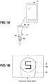
- FIGS. 1A to 1D are block diagrams showing an observation management system constructed such that a portable device 1 having a camera function and an observation device 2 for observing an observation object are linked to each other by communication.
- the portable device 1 composed of a portable telephone has a voice call function, an electronic mail function, an Internet access function (a Web access function), an image pick-up function (a camera function), a short distance communication function, and the like, and performs transmission and reception of data to and from the observation device 2 by short distance communication.
- the observation device 2 is used for observing the environment of an observation object (e.g., the growth environment of a plant such as a garden tree and a flower in the present embodiment). Its overall casing has the shape of an elongated hollow rod. Then, the overall hollow rod of the observation device 2 is formed in a tapered shape so that a lower part (e.g., the lower half) of the observation device 2 is buried into soil in a pot 3. Further, in the surface of the lower part, a plurality of pores 2a are formed for the purpose of aeration and water flow. Further, on the upper end surface of the observation device 2, an observation object ID (identification number "5" in the example shown) 2b used for identifying the observation object is formed by printing, stamping, or the like. Here, a user in a state of approaching the observation object takes an enlarged image around the upper end surface (the part of the observation object ID) of the observation device 2 by the camera function of the portable device 1 (see FIG. 1B ).
- an observation object ID identification number
- an arc-shaped handle 2c is formed in a protruding manner (molded integrally).
- the handle 2c is formed at a position that allows the casing to be stuck or extracted in a state that an index finger is applied on the handle 2c from the downside and that a finger pad of a thumb presses against an upper end surface of the casing.
- FIG. 3 is a block diagram showing basic components of the portable device 1.
- the CPU 11 is a central processing unit that operates by electric power supply from a power supply section 12 provided with a secondary battery (not shown) and that controls the overall operation of the portable device 1 in accordance with various kinds of programs in a storage section 13.
- the storage section 13 stores a program for implementing the present embodiment in accordance with the operation procedure shown in FIG. 9 and stores various kinds of applications.
- the storage section 13 has a work area used for temporarily storing various kinds of information necessary in the operation of the portable device 1 and also has an observation result table T1, an optimal environmental state table T2, a character image table T3, and the like, which are described later.
- the telephone communication section 14 is a broader-based communication section used for a voice call function, an electronic mail function, and an Internet access function.
- the image pick-up section 15 constitutes a camera section capable of taking a high definition image of a photographic object, and has an optical lens, an image sensor, an optical-system driving section, a stroboscope for illumination, an analog processing circuit, a signal processing circuit, and the like (not shown). Then, the image pick-up section 15 adjusts and controls optical zoom, and controls auto-focusing drive, shutter drive, exposure, balance, and the like.
- the display section 16 is constructed from a high definition liquid crystal display, an organic EL display, an electrophoresis type display (an electronic paper), or the like, and displays display information including text information and a standby image. Further, at the time of use of a camera function, the display section 16 serves as a finder screen for displaying a live view image (a monitor image) as a taken image. On the surface of the display section 16, a contact operation section (a transparent contact sensor) for detecting the contact of a finger is stacked so that a touch screen is constructed.
- the display section 16 is arranged in a front part of the portable device 1, whereas the image pick-up section 15 is arranged in a rear part of the portable device 1.
- the operation section 17 has a power ON/OFF button, a button used for switching the mode to a camera monitor mode, and the like (not shown). Then, the CPU 11 performs processing in accordance with the operation buttons.
- the short distance communication section 18 constitutes a Bluetooth (registered trademark) module for performing communication with the observation device 2, and operates within a communication available area (e.g., within a radius of 2 m).
- a search signal for searching for the observation device 2 is transmitted from the portable device 1. Then, when a response to this is obtained, communication link between the portable device 1 and the observation device 2 is established and hence data communication to each other is allowed. In this case, the portable device 1 receives and acquires an observation result transmitted from the observation device 2.
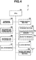
- FIG. 4 is a block diagram showing basic components of the observation device 2.
- the CPU 21 operates by electric power supply from a power supply section 22 provided with a battery (a primary battery or a secondary battery), and controls the overall operation of the observation device 2 in accordance with various kinds of programs in the storage section 23.
- the storage section 23 has an observation data memory T4 and an object ID memory T5 described later.
- the CPU 21 is connected to observation sections (various kinds of environment sensors) composed of I/O devices such as a sunshine recorder 24 for measuring a sunshine condition, an outdoor air temperature thermometer 25 for measuring outdoor air temperature, an outdoor air hygrometer 26 for measuring outdoor air humidity, a soil hygrometer 27 for measuring humidity on the surface of the soil in the pot 3.
- the CPU 21 is further connected to a clock section 28 for measuring the present date and time and a short distance communication section 29 for performing short distance radio communication with the portable device 1 (Bluetooth communication).
- a clock section 28 for measuring the present date and time
- a short distance communication section 29 for performing short distance radio communication with the portable device 1 (Bluetooth communication).
- each of the sunshine recorder 24, the outdoor air temperature thermometer 25, the outdoor air hygrometer 26, and the soil hygrometer 27 is a small electronic component capable of precision measurement.
- their configuration is widely known, and hence their description is omitted.
- the CPU 21 of the observation device 2 acquires growth environment (an observation result) observed by the sunshine recorder 24, the outdoor air temperature thermometer 25, the outdoor air hygrometer 26, and the soil hygrometer 27. Then, the growth environment (observation result) is stored and added into the observation data memory T4 in a manner of correspondence to the present date and time obtained from the clock section 28. Further, when communication link is established between the portable device 1 and the observation device 2 through the short distance communication section 29, the CPU 21 reads the contents of the object ID memory T5 and the observation data memory T4, and then transmits the data through the short distance communication section 29 to the portable device 1.
- the object ID memory T5 is a memory for storing an observation object ID (identification number "5" in the example in FIG. 1 ).
- the observation data memory T4 is a memory for storing the observation result (the observation result concerning growth environment) obtained by the sunshine recorder 24, the outdoor air temperature thermometer 25, the outdoor air hygrometer 26, and the soil hygrometer 27.
- FIG. 5 is a schematic vertical sectional view of the observation device 2.
- the top plate section 2d on the upper end side of the observation device 2 incorporates various kinds of electronic components such as the sunshine recorder 24, the outdoor air temperature thermometer 25, the outdoor air hygrometer 26, and an antenna 29a for the short distance communication section 29. Further, under these electronic components, a battery 22a serving as the power supply section 22 is built in. Further, the center partition board 2e of the observation device 2 incorporates the soil hygrometer 27. Further, in the surface on the lower end side of the observation device 2, the plurality of pores 2a described above are formed for the purpose of aeration and water flow.
- a plurality of valve members 2f for avoiding entering of soil into are formed in the parts where the pores 2a are performed.
- the upper half part and the lower half part of the observation device 2 are separable from each other at the center partition board 2e, and hence the lower half part of the observation device 2 can be changed suitably.
- a cassette of nutrient ampule may be inserted into the hollow part in the lower half part so that nutrient may be injected into soil.
- FIG. 6 is a diagram describing the observation result table T1 provided on the portable device 1 side.
- the observation result table T1 is a table in which the observation results (observation results concerning growth environment) transmitted from the observation device 2 are stored and managed for each date of observation and for each observation object ID.
- the vertical direction in the table corresponds to the "date of observation”
- the horizontal direction corresponds to the "observation object ID”.
- “No. 1", “No. 2", “No. 3", “No. 4", “No. 5",... indicate observation object IDs assigned to a plurality of the observation devices 2.
- a plant type is stored in correspondence to each observation object ID, like "cactus" for "No. 1", “vegetable A” for "No.
- the observation result table T1 stores the observation result data for a predetermined number of past days (e.g., one month). Then, in a full storage state that the observation result data for the predetermined number of days has already been stored, for example, older observation result data is deleted in a first-in first-out manner.
- FIG. 7 is a diagram describing the optimal environmental state table T2 provided on the portable device 1 side.
- the optimal environmental state table T2 is a table used for storing and managing the optimal environmental state for the growth of each type of observation object, and stores for each plant type the optimal state (a particular state) of the outdoor air temperature, the outdoor air humidity, the soil humidity, and the sunshine.
- the optimal state a particular state of the outdoor air temperature, the outdoor air humidity, the soil humidity, and the sunshine.
- the optimal environment is defined time-dependently along the time cycle from January to December. Further, the optimal environment also includes information concerning the optimal timing for additional fertilization, division, pot change, and the like.
- FIG. 8 is a diagram describing the character image table T3 provided on the portable device 1 side.
- the character image table T3 is a table used for storing and managing state representation information (a predetermined pictorial diagram such as a character image) that represents the present state of an observation object in accordance with the observation result of the observation object.
- the character image table T3 is used when a character image is to be identified in accordance with the observation result of the observation object. That is, the character image table T3 stores character images of the contents representing the states of "insufficient water”, “excessive water”, “excessive sunshine", and the like selected in accordance with the present state of the observation object.
- the character image table stores: a character image indicating that the growth environment of water, humidity, and sunshine is "optimal”; and a character image indicating that the environment is "excessive sunshine”.
- FIG. 9 is a flow chart showing the outline of operation constituting the feature of the present embodiment among the overall operation of the portable device 1.
- FIG. 9 is a flow chart of a procedure started and executed when the mode is changed to a camera monitor mode that a through image (a taken image) from the image pick-up section 15 is displayed as a monitor image.
- the user directs the image pick-up section 15 toward the observation object or its vicinity.
- the CPU 11 performs image pick-up monitor display in which a through image is acquired from the image pick-up section 15 and then is displayed as a monitor image on the display section 16 (step A1).
- the short distance communication section 18 is started so as to transmit a search signal for searching for the observation device 2 (step A2).
- step A3 the presence or absence of a response from the observation device 2 to the search signal is checked (step A3). Then, in a case that no response is obtained from the observation device 2 even when a predetermined time has elapsed (NO at step A3), the procedure escapes from the flow of FIG. 9 at this time.
- a response is received from the observation device 2 (YES at step A3), a communication available state is realized that communication is established between the portable device 1 and the observation device 2.
- step A4 when an observation result (an observation result concerning growth environment) together with the observation object ID is received and acquired from the observation device 2 (step A4), the received contents (the observation object ID and the observation result) are stored and added into the observation result table T1 (step A5).
- the processing of identifying the position of the transmission source that is, the processing of analyzing the receiving condition (radio wave intensity and the like) of the radio waves so as to identify the approximate position of the transmission source (the observation device 2) having transmitted the observation object ID (step A6).
- a direction guide for guiding the direction to the region of monitor image taking is displayed on the display section 16 (step A8).
- step A9 the procedure returns to the above-mentioned step A7 and hence it is checked whether the position of the transmission source has entered the region of monitor image taking.
- the observation result table T1 is searched on the basis of the observation object ID so that the type of observation object (plant) corresponding to the observation object ID is identified (step A10). Then, with reference to the contents of the observation result table T1 corresponding to this the observation object ID (or the plant type) and the contents of the optimal environmental state table T2, the state of change from the past observation result to the present observation result is determined as the present state of the observation object (step A11).
- the present state of the observation object is determined that: (1) “the state of insufficient water has continued for many days (insufficient water)” in comparison with the optimal environmental state for the foliage plant A; (2) “the state of excessive water has continued for many days (excessive water)” in comparison with the optimal environmental state for the cactus; (3) “the state of excessive sunshine has continued for many days (excessive sunshine)” in comparison with the optimal environmental state for the vegetable A; or (4) "the environment is optimal for the cactus".
- state representation information is acquired that represents the present state of the observation object. That is, on the basis of the above-mentioned determination result (e.g., "insufficient water”, “excessive water”, and “excessive sunshine”), the character image table T3 is searched so that a corresponding character image is selected, read, and acquired (step A12). Then, the selected character image is displayed and superposed at a position of the transmission source (the observation device 2) in the monitor image (step A13).
- the transmission source the observation device 2 in the monitor image
- step A 14 it is determined whether the above-mentioned determination result (the present state of the observation object) is of a state indicating a particular situation, that is, a state of danger, which means a state that "insufficient water”, “excessive water”, “excessive sunshine”, or the like has continued for an unusually long time (step A 14).
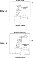
- FIG. 10 is a diagram showing an example of character image display performed when the determination result is optimal.
- FIG. 11 is a diagram showing an example of character image display performed when the determination result is of excessive sunshine, in which the upper end part of the observation device 2 and a character image are shown in the monitor image.
- the character image and a part of the observation device 1 are shown solely, and the observation objects, the pot 3, and the like are omitted.
- the portable device 1 when an image of the observation object or its vicinity is taken by the image pick-up section 15, the portable device 1 acquires an observation result of the observation object in the taken image (the monitor image). Further, after acquiring the state representation information that represents the present state of the observation object in accordance with the acquired observation result, the portable device 1 displays onto the display section 16 the state representation information in a manner of correspondence to the observation object in the taken image.
- the user can easily check the present state of the observation object at the site (near the observation object). This provides convenience.
- the portable device 1 receives and acquires by short distance communication the type of the observation object and its observation result transmitted from the observation device 2, and then determines the present state of the observation object in accordance with the result of comparison between the contents of the optimal environmental state table T2 corresponding to the type of the observation object and the acquired observation result.
- the present state can be determined for each observation object type.
- the portable device 1 receives and acquires an observation result concerning the observed growth observed by the environment sensors (the sunshine recorder 24, the outdoor air temperature thermometer 25, the outdoor air hygrometer 26, and the soil hygrometer 27) provided on the plant side.
- the environment sensors the sunshine recorder 24, the outdoor air temperature thermometer 25, the outdoor air hygrometer 26, and the soil hygrometer 27
- the portable device 1 transmits a search signal for searching for the observation object (the observation device 2) by short distance communication and then receives and acquires an observation result transmitted from the observation device 2 side in response to the search signal.
- the observation result is acquired merely by approaching the observation object (the observation device 2).
- the portable device 1 acquires a predetermined pictorial diagram (a character image) as state representation information expressing the present state of the observation object. This allows the user to recognize the present state of the observation object through an intuitively simple expression.
- the portable device 1 acquires state representation information that represents the present state of the observation object in accordance with the state of change from the past observation result to the present observation result of the observation object. Thus, the present state is determined appropriately and corresponding state representation information is acquired.
- the portable device 1 When the present state of the observation object is of a state indicating a particular situation (e.g., a state of danger), the portable device 1 performs display that specifies the particular state (e.g., display in red). Thus, the particular state is notified reliably.
- a state indicating a particular situation e.g., a state of danger
- the state representation information is displayed and superposed at the position of the observation object in the taken image. This clarifies the correspondence between the state representation information and the observation object.
- the observation device 2 transmits by short distance communication an observation result in response to a search signal for searching for an observation object transmitted from the portable device 1. Further, when an image of the observation object is taken by the image pick-up section 15, the portable device 1 in response to the search signal receives and acquires the observation result of the observation object transmitted from the observation device 2 by short distance communication, then acquires state representation information that represents the present state of the observation object in accordance with the acquired observation result, and then displays the state representation information onto the display section 16 in a manner of correspondence to the observation object in the taken image.
- the user can easily check the present state of the observation object at the site (near the observation object). This provides convenience.
- the observation device 2 is stuck and extracted in a state that the index finger is applied on the handle 2c from the downside and that the finger pad of the thumb presses against the upper end surface of the casing. Thus, sticking and extraction are achieved smoothly.
- Bluetooth communication has been employed between the portable device 1 and the observation device 2.
- employable configurations are not limited to this. That is, short distance communications such as infrared communication and non-contact ID card communication may be employed. Further, in place of such short distance communication, communication between the portable device 1 and the observation device 2 may be implemented through a local area network or a wide area network.
- the state representation information that represents the present state of the observation object has been read and acquired from the character image table T3.
- the state representation information may be received and acquired from a server device (not shown) via a local area network or a wide area network.
- the portable device 1 has received and acquired an observation result together with an observation object ID from the observation device 2 by short distance communication, and then has determined as the present state of the observation object the state of change from the past to the present observation result corresponding to the observation object ID (the plant type).
- the portable device 1 analyzes a monitor image so as to acquire the type of the observation object and its observation result by image recognition, and then determines the present state of the observation object in accordance with a result of comparison between the observation result and the optimal state corresponding to the type of the observation object.
- basically or literally like components are denoted by like numerals and their description is omitted.
- the following describe is given mainly for the features of the second embodiment.
- FIG. 12 is a diagram describing an optimal growth state table T6 provided in the storage section 13 of the portable device 1 according to the second embodiment.
- the optimal growth state table T6 is a table for storing color, growth, bloom condition, and the like for each plant type.
- the growth optimal state for "number and size of leaves", “bloom condition and number of flowers", “size and thickness of shaft”,... are stored in correspondence to each observation object (plant) type.
- the optimal growth state is stored for each plant type for each growth stage such as a sowing stage, a raising seedling stage, and a flowering stage, and for each season.
- FIG. 13 is a diagram describing a plant type table T7 provided in the storage section 13 of the portable device 1 according to the second embodiment.
- the plant type table T7 stores information describing the features of a plant of each type, and is used for identifying a plant type.
- the features of the individual parts of each plant type are described by the items of "leaf”, “stalk”, “flower”,....
- Each item describes feature information such as the color and the flower shape along the growth stage.
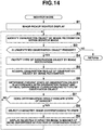
- FIG. 14 is a flow chart of a procedure started and executed when the mode is changed to a camera monitor mode according to the second embodiment.
- the CPU 11 performs image pick-up monitor display in which a through image is acquired from the image pick-up section 15 and then is displayed as a monitor image on the display section 16 (step B1).
- image recognition is performed on the monitor image so that the observation object is identified (step B2).
- the second embodiment employs a well-known image recognition technique. Thus, its detailed description is omitted.
- the image region of the observation object is comprehensively determined with taking into consideration the shape and the color of the plant as well as the relation with the surrounding pot and the like. Further, when a plurality of observation objects are present in the monitor image, each observation object is identified separately.
- step B3 it is checked whether an unidentified observation object which is not yet identify as an observation object is contained in the monitor image.
- a type e.g., a cactus and a foliage plant A
- step B4 image recognition is performed further so that a type (e.g., a cactus and a foliage plant A) is identified for each identified observation object (step B4).
- a photographic object a plant having a feature similar to the feature information of a plant is contained in the monitor image. Then, when a photographic object having a similar feature is included, the type is identified. Fur, for each observation object, the color, the growth, the bloom condition, and the like of the plant are observed comprehensively by image recognition so that an observation result is obtained (step B5).
- the present state of the observation object is determined on the basis of the contents of the optimal growth state table T6 corresponding to the type of the identified observation object and on the basis of the observation result (step B6). For example, it is determined that "in comparison with the optimal growth state, blooming is delayed by about one week", "the number of flowers is few", or the like. Then, it is checked whether this determination result is of a state indicating a particular situation, that is, of a state of danger that is far from the optimal state, like of a state that the growth is in danger of insufficient fertilizer, excessive sunshine, or the like (step B7). In contrast, when in a case of not being in a state of danger (NO at step B7), the procedure returns to the above-mentioned step B2 so that the presence or absence of another unidentified object is checked.
- step B7 when the present state of the observation object is of a state of danger (YES at step B7), a character image representing this state is selected (step B8). Then, the selected character image is displayed and superposed at the position of the observation object in the monitor image (step B9).
- step B8 when the position of display of the character image is touched, detailed information concerning the growth is popup-displayed. After that, the procedure returns to the above-mentioned step B2. Then, when an unidentified object is present in the monitor image (YES at step B3), the above-mentioned operation is repeated.
- the portable device 1 analyzes a monitor image taken by the image pick-up section 15 and observes the observation object in the monitor image so as to acquire an observation result.
- the present state of the observation object is easily checked at the site.
- a taken image is analyzed and an observation object in the taken image and is observed so that its type and its observation result are acquired by image recognition.
- the contents of the optimal growth state table T6 corresponding to the type of the observation object are compared with the acquired observation result so that the present state of the observation object is determined in accordance with the comparison result.
- the present state can be determined for each observation object type.
- observation objects in a state of danger are solely selected from the plurality of observation objects and then state representation information is displayed in the through image in a manner of correspondence to the observation object. This allows the user to easily and reliably find observation objects in a state of danger.
- an augmented reality (AR) technique may be combined with the camera function so that the user may be advised by physical feeling or by experience.
- a personified AR character image may be employed for advice presentation so that a plant accurately not capable of expressing intention may be represented as if it had intention and personality.
- This provides to the user: an affectional value that the feeling of a plant is virtually experienced through a character image; and a practical value that a difficulty in plant growth and management is alleviated.
- an AR character image is displayed exactly in the same space as the plant (the observation object), such expression is achievable as if the plant had intention and personality.
- it may be checked by image recognition whether the plant (the observation object) is located within the through image. Then, only when the plant is located within the image, the AR character image may be displayed together with the plant.
- a plant has been employed as an observation object.
- the present invention may be applied to an object which is favored as a hobby and whose optimality or inappropriateness in the situation cannot be determined easily, like a water tank environment in an aquarium, a bird such as a parakeet and a Java sparrow, and an automobile.
- an object which is favored as a hobby and whose optimality or inappropriateness in the situation cannot be determined easily, like a water tank environment in an aquarium, a bird such as a parakeet and a Java sparrow, and an automobile.
- the observation device 2 may be provided in the collar of a dog or a cat.
- the observation device 2 may be provided in the water tank.
- employable configurations are not limited to these.
- employable observation objects are not limited to a living thing such as a pet, and may be a perishable food such as meat and vegetable. Then, the storage environment of a refrigerator or a storage place, or alternatively the state of freshness may be observed. Alternatively, the chamber environment of a closet or the like may be observed. That is, the employed observation object is arbitrary.
- a character image has been displayed as state representation information.
- employable configurations are not limited to this. That is, other pictorial diagrams such as an icon having rich power of expression may be employed. Further, an advice balloon or the like may be employed as the state representation information.
- state representation information when state representation information is to be displayed in a manner of correspondence to the position of display of the observation object, the state representation information has been superposed at the position of display of the observation object.
- employable configurations are not limited to such superposition display as long as correspondence between the observation object and the state representation information is clear.
- the optimal environmental information has been stored in the optimal environmental state table T2 and the optimal growth state has been stored in the optimal growth state table T6.
- information to be stored is not limited to qt optimal one. That is, for example, the worst state or an unsuitable state may be stored.
- the state representation information (the character image) in the through image may be saved as a taken image. That is, the state representation information (the character image) may be combined into the through image, and then the combined image may be recorded and saved.
- the observation device 2 has been provided with the sunshine recorder 24, the outdoor air temperature thermometer 25, the outdoor air hygrometer 26, and the soil hygrometer 27.
- a soil water measuring instrument (not shown) for detecting a soil water content may be provided further.
- an electrode may be provided in the outer peripheral surface of the lower end part of the observation device 2 so that the water content may be measured directly on the basis of the electric current.
- an instrument for measuring the pH (the acidity) or the amount of ions in the soil may be provided in the hollow part in the lower half part of the observation device 2.
- the application is not limited to the portable device 1, and may be a PDA, a digital camera, a music player, or the like having a camera function. Obviously, the application may be a digital camera itself.
- each "device” or each “section” described in each embodiment described above may be separated into a plurality of casings for each function, and hence may be not contained in a single casing. Further, each step described in each flow chart described above need not be processed serially in time. That is, a plurality of steps may be processed in parallel, or alternatively may be processed separately and independently.
Landscapes
- Engineering & Computer Science (AREA)
- Life Sciences & Earth Sciences (AREA)
- Environmental & Geological Engineering (AREA)
- Health & Medical Sciences (AREA)
- Chemical & Material Sciences (AREA)
- Multimedia (AREA)
- Signal Processing (AREA)
- Atmospheric Sciences (AREA)
- Biodiversity & Conservation Biology (AREA)
- Ecology (AREA)
- Environmental Sciences (AREA)
- Food Science & Technology (AREA)
- General Physics & Mathematics (AREA)
- Geology (AREA)
- General Life Sciences & Earth Sciences (AREA)
- Medicinal Chemistry (AREA)
- Physics & Mathematics (AREA)
- Analytical Chemistry (AREA)
- Biochemistry (AREA)
- General Health & Medical Sciences (AREA)
- Remote Sensing (AREA)
- Immunology (AREA)
- Pathology (AREA)
- Testing Or Calibration Of Command Recording Devices (AREA)
- Management, Administration, Business Operations System, And Electronic Commerce (AREA)
- Studio Devices (AREA)
- Investigating Materials By The Use Of Optical Means Adapted For Particular Applications (AREA)
- Image Processing (AREA)
Applications Claiming Priority (1)
| Application Number | Priority Date | Filing Date | Title |
|---|---|---|---|
| JP2011030395A JP5510833B2 (ja) | 2011-02-16 | 2011-02-16 | 携帯端末装置及びプログラム |
Publications (2)
| Publication Number | Publication Date |
|---|---|
| EP2490177A2 true EP2490177A2 (fr) | 2012-08-22 |
| EP2490177A3 EP2490177A3 (fr) | 2013-06-12 |
Family
ID=45655807
Family Applications (1)
| Application Number | Title | Priority Date | Filing Date |
|---|---|---|---|
| EP20120155530 Withdrawn EP2490177A3 (fr) | 2011-02-16 | 2012-02-15 | Dispositif portable, système de gestion d'observations et support lisible sur ordinateur |
Country Status (4)
| Country | Link |
|---|---|
| US (2) | US9128213B2 (fr) |
| EP (1) | EP2490177A3 (fr) |
| JP (1) | JP5510833B2 (fr) |
| CN (2) | CN102647579B (fr) |
Cited By (1)
| Publication number | Priority date | Publication date | Assignee | Title |
|---|---|---|---|---|
| EP3929580A1 (fr) * | 2020-06-23 | 2021-12-29 | Yara International ASA | Procédé de détermination de la texture du sol |
Families Citing this family (21)
| Publication number | Priority date | Publication date | Assignee | Title |
|---|---|---|---|---|
| KR101415933B1 (ko) * | 2012-11-08 | 2014-07-08 | 재단법인대구경북과학기술원 | 식물 생장 모니터링 시스템 |
| JP6221027B2 (ja) * | 2012-12-21 | 2017-11-01 | 株式会社オサシ・テクノス | 拡張現実感技術による計測器管理システム及びプログラム |
| CN103905505A (zh) * | 2012-12-30 | 2014-07-02 | 青岛海尔软件有限公司 | 监控植物生长的手机应用系统 |
| JP6119254B2 (ja) * | 2013-01-11 | 2017-04-26 | カシオ計算機株式会社 | 通信装置、ar表示システム及びプログラム |
| EP2987397B1 (fr) * | 2013-04-18 | 2016-12-07 | Fujitsu Limited | Programme, dispositif et procédé de détermination de végétation |
| JP2013162800A (ja) * | 2013-05-16 | 2013-08-22 | Casio Computer Co Ltd | 通信装置並びにプログラム |
| FR3008210B1 (fr) * | 2013-07-03 | 2016-12-09 | Snecma | Procede et systeme de realite augmentee pour la supervision |
| TWI515695B (zh) * | 2013-07-05 | 2016-01-01 | 台達電子工業股份有限公司 | 狀態監控系統 |
| CN104429664B (zh) * | 2014-08-18 | 2017-03-01 | 柳超 | 基于移动终端的植物护理系统及方法 |
| CN104318108A (zh) * | 2014-10-28 | 2015-01-28 | 刘芳 | 一种植物培育方法与装置 |
| CN104941330B (zh) * | 2015-05-29 | 2017-08-01 | 小米科技有限责任公司 | 一种净化空气的方法和装置 |
| US10977748B2 (en) * | 2015-09-24 | 2021-04-13 | International Business Machines Corporation | Predictive analytics for event mapping |
| EP3459344A4 (fr) * | 2016-05-18 | 2019-12-11 | Sony Corporation | Dispositif de traitement d'informations, programme, et procédé de traitement d'informations |
| CN106293093A (zh) * | 2016-08-16 | 2017-01-04 | 合肥东上多媒体科技有限公司 | 数字多媒体接收机 |
| US20200060240A1 (en) * | 2016-11-29 | 2020-02-27 | Sony Corporation | Display control device, display control method, and program |
| CN106576499A (zh) * | 2016-11-30 | 2017-04-26 | 深圳前海弘稼科技有限公司 | 植物发芽的提示方法、提示装置、种植监控终端和服务器 |
| EP3553628A4 (fr) * | 2016-12-08 | 2019-11-27 | Sony Corporation | Dispositif de commande d'affichage, procédé de commande d'affichage et programme |
| MX2021003289A (es) * | 2018-09-21 | 2021-08-11 | Teralytic Holdings Inc | Plataforma de fusión de sensor multimodal extensible, para deteccion de terreno proximal, remota. |
| JP7265369B2 (ja) * | 2019-02-20 | 2023-04-26 | 東洋アルミニウム株式会社 | 盛り土の水分量測定システムおよび盛り土の水分量測定装置 |
| CN112580493B (zh) * | 2020-12-16 | 2021-11-09 | 广东省林业科学研究院 | 基于无人机遥感的植物识别方法、装置、设备及存储介质 |
| CN114877200B (zh) * | 2022-05-24 | 2023-05-30 | 郑州航空工业管理学院 | 水下视频监控系统的视距调节装置 |
Citations (1)
| Publication number | Priority date | Publication date | Assignee | Title |
|---|---|---|---|---|
| JP2010075172A (ja) | 2008-08-29 | 2010-04-08 | Seiko Instruments Inc | 植物育成ガイドシステム、植物環境測定装置及び植物育成管理装置 |
Family Cites Families (30)
| Publication number | Priority date | Publication date | Assignee | Title |
|---|---|---|---|---|
| JP2001204260A (ja) | 2000-01-31 | 2001-07-31 | Nissha Printing Co Ltd | インターフェースを備えた植木鉢 |
| US20020167587A1 (en) * | 2001-05-10 | 2002-11-14 | E.C.R Corporation | Monitoring system |
| JP2003152621A (ja) | 2001-11-12 | 2003-05-23 | Seiko Epson Corp | 無線通信装置および電子機器 |
| JP2005195341A (ja) | 2003-12-26 | 2005-07-21 | Casio Comput Co Ltd | 検索支援システム、装置および方法、ならびに、プログラム |
| JPWO2005072512A1 (ja) * | 2004-01-15 | 2007-07-26 | シナプス・リンク・コーポレーションSynapse Link,Corporation | 空心菜の保存方法、野菜の保存方法、及び加工食品 |
| DE502005005435D1 (de) * | 2005-02-02 | 2008-10-30 | Plantcare Ag | Vorrichtung und verfahren zur bestimmung von feuchtigkeit in einem medium |
| JP2006308493A (ja) | 2005-04-28 | 2006-11-09 | Ntt Docomo Inc | 携帯端末装置、応答通信装置並びに被探索対象表示システム及び方法 |
| JP4876439B2 (ja) * | 2005-05-31 | 2012-02-15 | パナソニック電工株式会社 | 植物育成情報の提供方法 |
| US20070082600A1 (en) * | 2005-10-07 | 2007-04-12 | Bryan Asvestas | Apparatus and method for selecting and growing living plants |
| JP4012554B2 (ja) | 2005-11-02 | 2007-11-21 | 独立行政法人農業・食品産業技術総合研究機構 | 植物生育情報処理システム |
| US7587297B2 (en) * | 2006-03-02 | 2009-09-08 | Plant Sense, Inc. | Computerized system for targeted horticultural advertising |
| JP2007289657A (ja) * | 2006-03-28 | 2007-11-08 | Fujifilm Corp | 画像記録装置、画像記録方法、および画像記録プログラム |
| CN2904057Y (zh) * | 2006-04-25 | 2007-05-23 | 张凡 | 便携式土壤参数采集装置 |
| CN100476662C (zh) * | 2006-08-16 | 2009-04-08 | 中山大学 | 一种数字家庭中的植物智能培育装置 |
| US20080051033A1 (en) * | 2006-08-28 | 2008-02-28 | Charles Martin Hymes | Wireless communications with visually- identified targets |
| JP5422869B2 (ja) * | 2006-09-07 | 2014-02-19 | カシオ計算機株式会社 | 植物管理装置、植物管理システム及びプログラム |
| US8168121B2 (en) * | 2006-12-05 | 2012-05-01 | Elkins Earthworks, Llc | Portable gas monitor |
| JP2008145226A (ja) * | 2006-12-08 | 2008-06-26 | Olympus Corp | 欠陥検査装置及び欠陥検査方法 |
| ATE530121T1 (de) * | 2006-12-18 | 2011-11-15 | Esaote Spa | Ergonomisches gehäuse fur einen elektroakustischen wandler und ultraschallsonde mit einem solchen gehäuse |
| JP5393446B2 (ja) * | 2007-02-26 | 2014-01-22 | オリンパスメディカルシステムズ株式会社 | 画像取得装置 |
| JP2008217702A (ja) * | 2007-03-07 | 2008-09-18 | Fujifilm Corp | 撮影装置および撮影方法 |
| AP2010005108A0 (en) | 2007-06-06 | 2010-02-28 | Tata Consultancy Services Ltd | A mobile based advisory system and a method thereof |
| CN101216482B (zh) * | 2008-01-18 | 2010-12-08 | 中国农业大学 | 一种农田环境的监测装置 |
| CN201215679Y (zh) * | 2008-06-30 | 2009-04-01 | 孙爱中 | 花卉种植用监控报警器 |
| JP2010033326A (ja) * | 2008-07-29 | 2010-02-12 | Nec Corp | 食事・健康管理システム、方法及びプログラム |
| CN201360408Y (zh) * | 2009-01-21 | 2009-12-16 | 邵亚军 | 手提式播种施肥器 |
| CN101536653A (zh) * | 2009-04-21 | 2009-09-23 | 黄伟聪 | 一种带有监控装置的植物栽培容器 |
| CN201408081Y (zh) * | 2009-04-22 | 2010-02-17 | 南昌航空大学 | 植物心情代言装置 |
| US20120029313A1 (en) * | 2010-07-27 | 2012-02-02 | Alison Burdett | System and method for tracking vital-signs monitor patches |
| JP5621880B2 (ja) | 2013-05-16 | 2014-11-12 | カシオ計算機株式会社 | 観測管理システム並びに観測装置 |
-
2011
- 2011-02-16 JP JP2011030395A patent/JP5510833B2/ja active Active
-
2012
- 2012-02-15 US US13/396,876 patent/US9128213B2/en active Active
- 2012-02-15 EP EP20120155530 patent/EP2490177A3/fr not_active Withdrawn
- 2012-02-16 CN CN201210035229.XA patent/CN102647579B/zh active Active
- 2012-02-16 CN CN201510187741.XA patent/CN104796668B/zh not_active Expired - Fee Related
-
2015
- 2015-07-30 US US14/814,041 patent/US9523791B2/en active Active
Patent Citations (1)
| Publication number | Priority date | Publication date | Assignee | Title |
|---|---|---|---|---|
| JP2010075172A (ja) | 2008-08-29 | 2010-04-08 | Seiko Instruments Inc | 植物育成ガイドシステム、植物環境測定装置及び植物育成管理装置 |
Cited By (3)
| Publication number | Priority date | Publication date | Assignee | Title |
|---|---|---|---|---|
| EP3929580A1 (fr) * | 2020-06-23 | 2021-12-29 | Yara International ASA | Procédé de détermination de la texture du sol |
| WO2021259733A1 (fr) * | 2020-06-23 | 2021-12-30 | Yara International Asa | Procédé de détermination de la texture de la terre |
| CN115917314A (zh) * | 2020-06-23 | 2023-04-04 | 亚拉国际有限公司 | 用于确定土壤质地的方法 |
Also Published As
| Publication number | Publication date |
|---|---|
| CN102647579A (zh) | 2012-08-22 |
| EP2490177A3 (fr) | 2013-06-12 |
| JP2012165709A (ja) | 2012-09-06 |
| CN102647579B (zh) | 2015-05-13 |
| US9128213B2 (en) | 2015-09-08 |
| US20160041303A1 (en) | 2016-02-11 |
| US9523791B2 (en) | 2016-12-20 |
| JP5510833B2 (ja) | 2014-06-04 |
| US20120206598A1 (en) | 2012-08-16 |
| CN104796668B (zh) | 2018-07-10 |
| CN104796668A (zh) | 2015-07-22 |
Similar Documents
| Publication | Publication Date | Title |
|---|---|---|
| US9523791B2 (en) | Observation device and observation management system | |
| JP5621880B2 (ja) | 観測管理システム並びに観測装置 | |
| JP5729476B2 (ja) | 撮影装置、および撮影支援プログラム | |
| JP6276100B2 (ja) | 農作物の成長観察システム | |
| US10586353B2 (en) | Plant information acquisition system, plant information acquisition device, plant information acquisition method, crop management system and crop management method | |
| JP2013051926A (ja) | 情報端末装置及び育成管理システム並びにプログラム | |
| US9036056B2 (en) | Image communication system, terminal device, management device and computer-readable storage medium | |
| US20140026474A1 (en) | Automated grow system | |
| JP6551943B2 (ja) | 生育管理装置、生育管理方法、及び、プログラム | |
| KR20170101692A (ko) | 사물 인터넷 기반 스마트 화분 및 그 관리 시스템 | |
| ES2908475T3 (es) | Control de organismos nocivos | |
| CN105577784B (zh) | 用于养殖的方法和装置 | |
| JP5954460B2 (ja) | 観測装置及び観測管理システム | |
| WO2009084910A2 (fr) | Système d'exploitation agricole ubiquiste | |
| US11145009B2 (en) | Method for supporting a user in an agricultural activity | |
| JP2013162800A (ja) | 通信装置並びにプログラム | |
| US20260072927A1 (en) | Plant information display method and apparatus, and computer-readable storage medium | |
| Huang et al. | Feeding preference and movement of Nezara viridula and Euschistus servus (Hemiptera: Pentatomidae) on individual cotton plants | |
| KR20160146441A (ko) | 벽걸이 화분 식물 성장 시스템 | |
| KR102314894B1 (ko) | 증강현실을 이용한 가상객체 관리 방법, 증강현실을 이용한 행사 관리 방법 및 모바일 단말 | |
| CN113506183A (zh) | 农业景观鸟类物种田间调查记录客户端系统 | |
| KR102785181B1 (ko) | 모바일 단말을 이용한 생장 정보 추출 및 생장 환경 제어 시스템 | |
| JP2021022076A (ja) | 通信端末、方法及びプログラム | |
| KR101005665B1 (ko) | 알에프아이디 기술기반을 이용한 산림자원관리 시스템 및 그의 제어방법 | |
| CN101751203A (zh) | 具有个性化桌面的可携式电子装置与显示方法 |
Legal Events
| Date | Code | Title | Description |
|---|---|---|---|
| PUAI | Public reference made under article 153(3) epc to a published international application that has entered the european phase |
Free format text: ORIGINAL CODE: 0009012 |
|
| 17P | Request for examination filed |
Effective date: 20120215 |
|
| AK | Designated contracting states |
Kind code of ref document: A2 Designated state(s): AL AT BE BG CH CY CZ DE DK EE ES FI FR GB GR HR HU IE IS IT LI LT LU LV MC MK MT NL NO PL PT RO RS SE SI SK SM TR |
|
| AX | Request for extension of the european patent |
Extension state: BA ME |
|
| PUAL | Search report despatched |
Free format text: ORIGINAL CODE: 0009013 |
|
| AK | Designated contracting states |
Kind code of ref document: A3 Designated state(s): AL AT BE BG CH CY CZ DE DK EE ES FI FR GB GR HR HU IE IS IT LI LT LU LV MC MK MT NL NO PL PT RO RS SE SI SK SM TR |
|
| AX | Request for extension of the european patent |
Extension state: BA ME |
|
| RIC1 | Information provided on ipc code assigned before grant |
Ipc: G06T 7/00 20060101AFI20130507BHEP |
|
| 17Q | First examination report despatched |
Effective date: 20170120 |
|
| STAA | Information on the status of an ep patent application or granted ep patent |
Free format text: STATUS: THE APPLICATION IS DEEMED TO BE WITHDRAWN |
|
| 18D | Application deemed to be withdrawn |
Effective date: 20191113 |