EP2490194A2 - Appareil, procédé et système de communication - Google Patents
Appareil, procédé et système de communication Download PDFInfo
- Publication number
- EP2490194A2 EP2490194A2 EP12152852A EP12152852A EP2490194A2 EP 2490194 A2 EP2490194 A2 EP 2490194A2 EP 12152852 A EP12152852 A EP 12152852A EP 12152852 A EP12152852 A EP 12152852A EP 2490194 A2 EP2490194 A2 EP 2490194A2
- Authority
- EP
- European Patent Office
- Prior art keywords
- data
- read
- communication apparatus
- communication
- response
- Prior art date
- Legal status (The legal status is an assumption and is not a legal conclusion. Google has not performed a legal analysis and makes no representation as to the accuracy of the status listed.)
- Granted
Links
Images




Classifications
-
- H—ELECTRICITY
- H04—ELECTRIC COMMUNICATION TECHNIQUE
- H04Q—SELECTING
- H04Q9/00—Arrangements in telecontrol or telemetry systems for selectively calling a substation from a main station, in which substation desired apparatus is selected for applying a control signal thereto or for obtaining measured values therefrom
-
- H—ELECTRICITY
- H04—ELECTRIC COMMUNICATION TECHNIQUE
- H04Q—SELECTING
- H04Q2209/00—Arrangements in telecontrol or telemetry systems
- H04Q2209/70—Arrangements in the main station, i.e. central controller
- H04Q2209/75—Arrangements in the main station, i.e. central controller by polling or interrogating the sub-stations
- H04Q2209/753—Arrangements in the main station, i.e. central controller by polling or interrogating the sub-stations where the polling of the sub-stations is synchronous
Definitions
- the present invention relates to communication apparatuses, communication systems, and communication methods.
- Each of the initiator and the target generates data at an arbitrary timing.
- the initiator Upon completing the generation of data to be sent to the target, the initiator sends a communication request to the target at an arbitrary timing and can send the data to the target.
- the target even if the target completes the generation of data to be sent to the initiator, it is difficult for the target to send the data to the initiator until the target receives a communication request from the initiator.
- the present invention helps to provide communication apparatuses, a communication system, and a communication method, in which the communication apparatus that works as a target can send data at an arbitrary timing to a communication apparatus that works as an initiator.
- One embodiment of the present invention provides a communication apparatus including: a data generating unit that generates write data to be sent to any other communication apparatus at an arbitrary timing; a communication unit that repeatedly sends a read request to the other communication apparatus until the write data is generated and, at the same time, repeatedly receives a read response sent from the other communication apparatus in response to the read request; and a data acquisition unit that acquires read data, which is sent along with the read response by the other communication apparatus, when the read data is generated at an arbitrary timing by the other communication apparatus.
- Another embodiment of the present invention provides a communication apparatus including: a data generating unit that generates read data to be sent to any other communication apparatus at an arbitrary timing; and a communication unit that repeatedly receives a read request sent from the other communication apparatus until write data is generated by the other communication apparatus and, at the same time, repeatedly sends a read response to the other communication apparatus in response to the read request, and sends the read data along with the read response to the other communication apparatus when the read data is generated.
- Another embodiment of the present invention provides a communication system having a first communication apparatus and a second communication apparatus, in which the first communication apparatus includes: a data generating unit that generates write data to be sent to a second communication apparatus at an arbitrary timing; a communication unit that repeatedly sends a read request to the second communication apparatus until the write data is generated and, at the same time, repeatedly receives a read response sent from the second communication apparatus in response to the read request; and a data acquisition unit that acquires read data, which is sent along with the read response by the second communication apparatus, when the read data is generated at an arbitrary timing by the second communication apparatus, and the second communication apparatus includes: a data generating unit that generates read data to be sent to the first communication apparatus at an arbitrary timing; and a communication unit that repeatedly receives the read request sent from the first communication apparatus until the write data is generated by the first communication apparatus and, at the same time, repeatedly sends the read response to the first communication apparatus in response to the read request, and sends the read data along with the read response to the first communication apparatus when
- Another embodiment of the present invention provides a communication method including: causing a first communication apparatus to generate write data to be sent to a second communication apparatus at an arbitrary timing; causing the second communication apparatus to generate read data to be sent to the first communication apparatus at an arbitrary timing; causing the first communication apparatus to repeatedly send a read request to the second communication apparatus until the write data is generated; causing the second communication apparatus to repeatedly send a read response in response to the read request to the first communication apparatus; and causing the first communication apparatus to receive the read request and acquire the read data, which is sent along with the read response by the second communication apparatus, when the read data is generated by the second communication apparatus.
- two communication apparatuses a communication system, and a communication method, in which one of the two communication apparatuses that works as a target can send data at an arbitrary timing to the other that works as an initiator, may be provided.
- FIG. 1 is a diagram showing an overview of a communication method according to this embodiment.
- communication is performed between a first communication apparatus working as an initiator 10 and a second communication apparatus working as a target 20.
- the initiator 10 includes a reader/writer
- the target 20 includes an RFID (radio frequency identification) module and a host (CPU).
- Passive communication is performed between the initiator 10 and the target 20 in response to a communication request (one of commands) such as a write request or a read request sent by the initiator 10.
- the initiator 10 generates write data to be sent to the target 20 at an arbitrary timing, and the target 20 generates read data to be sent to the initiator 10 at an arbitrary timing. After generating write data, the initiator 10 sends a write request and the write data to the target 20, and the target 20 acquires the write data in response to the write request.
- the initiator 10 repeatedly sends a read request to the target 20 until the initiator 10 generates write data, and the target 20 repeatedly sends a read response in response to the read request to the initiator 10. Subsequently, after the target 20 generates read data, the initiator 10 acquires the read data along with the read response sent by the target 20.
- the target 20 can send the read data to the initiator 10 at an arbitrary timing by sending the read data at the timing of the read data generation in response to the read request the target 20 repeatedly receives. Therefore, two-way communication can be effectively performed between the initiator 10 and the target 20 in synchronization with the timing of the read data generation or the write data generation.
- FIG. 2 is a diagram showing passive communication performed between the initiator 10 and the target 20.
- passive communication is performed between the initiator 10 and the target 20 in compliance with an NFC (near field communication) protocol or the like.
- the NFC protocol is a protocol for short range wireless communication that employs electromagnetic induction phenomenon and uses a single frequency carrier, for example, 13.56 MHz in the ISM (industrial, scientific and medical) band.
- Short range wireless communication is communication performed between two communication apparatuses spaced apart from each other by about several tens of centimeters, and this type of wireless communication includes communication performed between two communication apparatuses that are contacting each other.
- communication is performed in a passive mode or in an active mode.
- a passive mode as shown in FIG. 2 , communication is performed in such a way that one communication apparatus works as the initiator 10, and the other works as the target 20.
- the initiator 10 sends a communication request (one of commands) to the target 20, and the target 20 sends a communication response (one of responses) to the initiator 10 in response to the communication request.
- the initiator 10 sends the communication request and data to the target 20 by modulating an electromagnetic wave R (used as a carrier wave) generated by the initiator 10 itself (in the state ST21), and the target 20 sends the communication response and data to the initiator 10 by load-modulating the electromagnetic wave R (used as the carrier wave) generated by the initiator 10 (in the state ST22).
- an electromagnetic wave R used as a carrier wave
- the target 20 sends the communication response and data to the initiator 10 by load-modulating the electromagnetic wave R (used as the carrier wave) generated by the initiator 10 (in the state ST22).
- FIG. 3 is a block diagram showing the functional configuration of the communication system. As shown in FIG. 3 , the communication system includes the initiator 10 and the target 20.
- the initiator 10 includes a controller and a reader/writer connected to the controller (neither is shown).
- the controller can be a personal computer, a PDA, a mobile phone, a consumer electronics device, or the like. Alternatively, the controller can be a CPU mounted in the above devices.
- the target 20 includes a host (CPU) and an RFID module connected to the host (neither is shown).
- the host can be a personal computer, a PDA, a mobile phone, a consumer electronics device, or the like. Alternatively, the host can be a CPU mounted in the above devices.
- the controller and the reader/writer are connected to each other via a communication interface.
- the host and the RFID are also connected to each other via a communication interface.
- the first communication apparatus working as the initiator 10 includes a control unit 11, a memory unit 13, and a data processing unit 15.
- the control unit 11 works as a data generating unit and a data acquisition unit
- the data processing unit 15 works as a communication unit.
- FIG. 3 shows that the controller unit 11, the memory unit 13, and the data processing unit 15 included in the initiator 10 are configured as an all-one-unit, but each of these units can be provided as a separate unit.
- the control unit 11 generates write data to be sent to the target 20 at an arbitrary timing.
- the controller 11 judges whether the generation of the write data is completed or not, and, if completed, generates a write request, and controls the data processing unit 15 so that the write request as well as the write data is sent to the target 20.
- the controller 11 repeatedly generates a read request until the write data is generated, and controls the data processing unit 15 so that the read request is sent to the target 20.
- the control unit 11 controls the data processing unit 15 so that the data processing unit 15 acquires read data along with a read response sent from the target 20 when the target 20 generates the read data.
- the control unit 11 stores the acquired read data in the memory unit 13.
- the data processing unit 15 sends the write request along with the write data to the target 20 and also sends the read request to the target 20 by sending an electromagnetic wave that the data processing unit 15 modulates with the use of an antenna coil or the like.
- the data processing unit 15 receives a write response from the target 20 and also receives the read response along with the read data from the target 20 by receiving an electromagnetic wave load-modulated by the target 20.
- the data processing unit 15 repeatedly sends the read request to the target 20 until the write data is generated, and sends the write request along with the write data to the target 20 when the write data is generated.
- the second communication apparatus working as the target 20 includes a control unit 21, a memory unit 23, and a data processing unit 25.
- the control unit 21 works as a data generating unit and a data acquisition unit
- the data processing unit 25 works as a communication unit.
- FIG. 3 shows that the controller unit 21, the memory unit 23, and the data processing unit 25 included in the target 20 are configured as an all-one-unit, but each of these units can be provided as a separate unit.
- the control unit 21 Upon receiving the write request, the control unit 21 acquires the write data sent by the initiator 10 along with the write request, and stores the write data in the memory unit 23. In addition, the control unit 21 controls the data processing unit 25 so that the write response is sent to the initiator 10. The control unit 21 generates the read data to be sent to the initiator 10 at an arbitrary timing. Upon receiving the read request, the controller 21 judges whether the generation of the read data is completed or not, and, if completed, controls the data processing unit 25 so that the read response is sent to the initiator 10.
- the control unit 21 controls the data processing unit 25 so that the data processing unit 25 sends the read response as well as the read data to the initiator 10 when the generation of the read data is completed, and sends the read response to the initiator 10 when the generation of the read data is not completed.
- the data processing unit 25 receives the write request along with the write data sent from the initiator 10 and also receives the read request sent from the initiator 10 by receiving the electromagnetic wave that is modulated with the use of the antenna coil or the like. In addition, the data processing unit 25 sends the write response to the initiator 10 and also sends the read response to the initiator 10 by load-modulating and sending the electromagnetic wave sent by the initiator 10. The data processing unit 25 sends the read data as well as the read response to the initiator 10 when the generation of the read data is completed, and sends only the read response to the initiator 10 when the generation of the read data is not completed.
- FIG. 4 is a flowchart showing the operation of the initiator 10
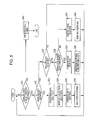
- FIG. 5 is a flowchart showing the operation of the target 20.
- a short range wireless communication link is established between the initiator 10 and the target 20 through a polling request and a polling response.
- the control unit 11 of the initiator 10 generates write data at an arbitrary timing.
- the write data is data that is sent from the initiator 10 to the target 20 so that the data is stored in the target 20.
- the control unit 11 judges whether the generation of the write data is completed or not (at step S11).
- the control unit 11 performs write processing at step S12 to step S16 when the generation of the write data to be sent to the target 20 is completed ("Yes" at step S11), and performs read processing at step S17 to step S22 when the generation of the write data to be sent to the target 20 is not completed ("No" at step S11).
- the control unit 11 In the write processing, the control unit 11 generates a write request as a communication request (at step S12).
- the write request is generated in order for the initiator 10 to request the target 20 to write data.
- the control unit 11 supplies the write request and the write data to the data processing unit 15.
- the write data can be directly supplied to the data processing unit 15 by the control unit 11, or can be supplied after being read out from the memory 13 by the control unit 11.
- the data processing unit 15 sends the write request and the write data to the target 20 (at step S13), and receives a write response sent from the target 20 in response to the write request (at step S14).
- the write data can be sent in the form of being included in the write request, or can be sent independently of the write request.
- the write response is generated by the target 20 in order for the target 20 to inform the initiator 10 of the result of the data writing.
- the data processing unit 15 supplies the received write response to the control unit 11.
- the control unit 11 judges whether the data is properly written into the target 20 or not on the basis of the write response (at step S15). If it is judged that the data is properly written ("Yes” at step S15), the control unit 11 deletes the data, which is stored in the memory unit 13 and has already been written into the target 20, from the memory unit 13 (at step S16). If it is not judged that the data is properly written ("No" at step S15), the control unit 11 makes an error response (at step S23). In this error response, the control unit 11 can cause the flow to go back to the process at step S12 to restart the write processing, or can cause the flow to go back to the process at step S11 to judge whether the generation of the write data is completed or not.
- the control unit 11 in the read processing, the control unit 11 generates a read request as a communication request (at step S17).
- the read request is generated in order for the initiator 10 to request the target 20 to read out data.
- the control unit 11 supplies the read request to the data processing unit 15.
- the data processing unit 15 sends the read request to the target 20 (at step S18), and receives a read response sent from the target 20 in response to the read request (at step S19).
- the read response is generated by the target 20 in order for the target 20 to inform the initiator 10 of the result of the data reading.
- the data processing unit 15 supplies the received read response to the control unit 11.
- the data processing unit 15 receives read data along with the read response sent from the target 20 when the generation of the read data is completed by the target 20, that is, when the generation of the read data to be sent to the initiator 10 is completed by the target 20 that has already received the read request from the initiator 10. On the other hand, the data processing unit 15 does not receive the read data from the target 20 when the generation of the read data is not completed by the target 20.
- the read data can be received in the form of being included in the read response, or can be received independently of the read response.
- the control unit 11 judges whether the data is properly read out by the target 20 or not on the basis of the read response (at step S20). If it is judged that the data is properly read out ("Yes” at step S20), the control unit 11 judges whether the data processing unit 15 receives the read data or not (at step S21). If it is not judged that the data is properly read ("No” at step S20), the control unit 11 makes an error response (at step S23). In this error response, the control 11 1 can cause the flow to go back to the process at step S17 to restart the read processing, or can cause the flow to go back to the process at step S11 to judge whether the generation of the write data is completed or not. If the data processing unit 15 has received the read data ("Yes" at step S21), the control unit 11 acquires the read data from the data processing unit 15, and stores the read data in the memory unit 13 (at step S22).
- the data processing unit 15 can receive dummy data along with the read response sent from the target 20.
- the dummy data is essentially not data to be sent to the initiator 10, and it is data useless for the initiator 10.
- the dummy data can be received in the form of being included in the read response, or can be received independently of the read response.
- control unit 11 restarts the process at step S11.
- the control unit 11 repeatedly performs the above-described processes as long as the short range wireless communication link is established between the initiator 10 and the target 20.
- the control unit 21 of the target 20 receives a communication request (one of commands) from the reader/writer via the data processing unit 25. As shown in FIG. 5 , the control unit 21 judges whether the communication request is properly received or not (at step S31). If it is judged that the communication request is properly received ("Yes" at step S31), the control unit 21 performs the following processes. If it is not judged that the communication request is properly received ("No” at step S31), the control unit 21 makes an error response (at step S43). The control unit 21 performs write processing at step S33 to step S36 when receiving a write request ("Yes" at step S32), and performs read processing at step S38 to step S42 when receiving a read request ("Yes" at step S37).
- the control unit 21 deletes the read data that has been last sent to the initiator 10 as well as the last read response from the memory unit 13 (at step S33).
- the above process is performed because the fact that the write request is received by the control unit 21 means that the last read processing has been successfully completed between the initiator 10 and the target 20.
- the control unit 21 acquires write data as well as the write request, which is received by the data processing unit 25, from the data processing unit 25, and stores the write data in the memory unit 23 (at step S34).
- the control unit 21 supplies the result of the data writing to the data processing unit 25.
- the data processing unit 25 generates a write response including the result of the data writing (at step S35), and sends the write response to the initiator 10 (at step S36).
- the control unit 21 judges whether the generation of read data to be sent is completed or not (at step S38).
- the control unit 21 generates the read data at an arbitrary timing.
- the read data is data to be sent from the target 20 so that the read data is read out by the initiator 10.
- the control unit 21 supplies the result of the data reading along with the read data to the data processing unit 25.
- the data processing unit 25 generates a read response including the result of the data reading (at step S39), and sends the read response along with the read data to the initiator 10 (at step S40).
- the read data can be sent in the form of being included in the read response, or can be sent independently of the read response.
- the control unit 21 supplies the result of the data reading to the data processing unit 25.
- the data processing unit 25 generates a read response including the result of the data reading (at step S41), and sends the read response to the initiator 10 (at step S42).
- the data processing unit 25 can send dummy data along with the read response to the initiator 10. Again in this case, the dummy data can be sent in the form of being included in the read response, or can be sent independently of the read response.
- control unit 21 makes the flow to go back to the step S31 to restart the operation of the target 20.
- the control unit 21 repeatedly performs the above-described processes as long as the short range wireless communication link is established between the initiator 10 and the target 20.
- FIG. 6 is a sequence diagram showing a communication method according to one embodiment of the present invention. In the following description, it will be assumed that a short range wireless communication link is established between the initiator 10 and the target 20 through a polling request and a polling response.
- FIG. 6 An example of the sequence diagram in FIG. 6 shows four timings I1, I2, I3, and I4 in the control unit 11 of the initiator 10, and it will be assumed that write data (data 2) is generated just before a timing I3 (at step S70).
- write data data 2 is generated just before a timing I3 (at step S70).
- timings T1, T2, T3, and T4 in the control unit 21 of the target 20, and it will be assumed that read data (data 1) is generated just before a timing T2 (at step S60).
- the initiator 10 Because the generation of write data is not completed by the control unit 11 of the initiator 10 before the timing I1, the initiator 10 generates read request and supplies the read request to the data processing unit 15 (at step S51). The data processing unit 15 sends the read request to the target 20 (at step S52).
- the data processing unit 25 of the target 20 receives the read request, and notifies the control unit 21 of the read request (at step S53). Because the generation of read data is not completed by the control unit 21 before the timing T1, the control unit 21 supplies void data or dummy data to the data processing unit 25 (at step S54). The data processing unit 25 generates read response, and sends the read response along with the void data or dummy data to the initiator 10 (at step S55).
- the data processing unit 15 of the initiator 10 receives the read response, and notifies the control unit 11 of the read response (at step S56). In this case, the data processing unit 15 can supply the read response without no read data, or can supply the read response with the dummy data to the control unit 11.
- the initiator 10 generates read request and supplies the read request to the data processing unit 15 (at step S61).
- the data processing unit 15 sends the read request to the target 20 (at step S62).
- the data processing unit 25 of the target 20 receives the read request, and notifies the control unit 21 of the read request (at step S63). Because the generation of read data (data 1) is completed by the control unit 21 before the timing T2 (at step S60), the control unit 21 supplies the read data to the data processing unit 25 (at step S64). The data processing unit 25 generates read response, and sends the read response along with the read data to the initiator 10 (at step S65).
- the data processing unit 15 of the initiator 10 receives the read response, and notifies the control unit 11 of the read response (at step S66). In this case, the data processing unit 15 supplies the read data to the control unit 11, and the control unit 11 acquires the read data to store the read data in the memory unit 13. As a result, the read data is read out from the target 20 by the initiator 10.
- the control unit 11 generates write request and supplies the write request as well as the write data to the data processing unit 15 (at step S71).
- the data processing unit 15 sends the write request as well as the write data to the target 20 (at step S72).
- the data processing unit 25 of the target 20 Upon receiving the write request, the data processing unit 25 of the target 20 notifies the control unit 21 of the write request and sends the write data to the control unit 21 (at step S73).
- the control unit 21 acquires the write data to store the write data in the memory unit 23, and notifies the data processing unit 25 of the result of the data writing (OK) (at step S74).
- the write data is written in the target 20 by the initiator 10.
- the data processing unit 25 generates write response, and sends the write response to the initiator 10 (at step S75).
- the data processing unit 15 of the initiator 10 receives the write response, and notifies the control unit 11 of the write response (at step S76).
- control unit 11 generates read request and supplies the read request to the data processing unit 15 (at step S81).
- the data processing unit 15 sends the read request to the target 20 (at step S82).
- the data processing unit 25 of the target 20 Upon receiving the read request, the data processing unit 25 of the target 20 notifies the control unit 21 of the read request (at step S83). Because the generation of read data is not completed by the control unit 21 before the timing T4, the control unit 21 supplies void data or dummy data to the data processing unit 25 (at step S84). The data processing unit 25 generates read response, and sends the read response along with the void data or dummy data to the initiator 10 (at step S85).
- the data processing unit 15 of the initiator 10 receives the read response, and notifies the control unit 11 of the read response (at step S86). In this case, the data processing unit 15 can supply the read response without no read data, or can supply the read response with the dummy data to the control unit 11.
- FIG. 7 is a diagram showing examples of data structures of communication requests/communication responses.
- a write request is equivalent to an "Updated Command" defined by the specification, and its data structure Wreq includes fields for a request identifier (ID), a communication ID (IDm), the number of services (NOS), a service code list (SLST), the number of blocks (NOB), a block list (BLST), and write data (DATA).
- the write request with this data structure Wreq that includes write data is sent from the initiator 10 to the target 20.
- a write response is equivalent to an "Updated Response" defined by the specification, and its data structure Wreq includes fields for a response identifier (ID), a communication ID (IDm), and a result code (SF).
- the data processing unit 25 of the target 20 Upon receiving a write request, the data processing unit 25 of the target 20 extracts the request identifier, the number of blocks, the block list, and the write data of the write request, and supplies them to the control unit 21.
- the number of blocks and the block list respectively indicate the number of blocks and the block codes of write data to be written in the target 20.
- the control unit 21 supplies a result code showing the result of the data writing to the data processing unit 25.
- the result code indicates whether the write processing is successfully completed or not.
- the data processing unit 25 generates a write response including data of a response identification and a communication ID, and sends the write response along with the result code to the initiator 10.
- a read request is equivalent to a "Check Command" defined by the specification, and its data structure Rreq includes fields for a request identifier (ID), a communication ID (IDm), the number of services (NOS), a service code list (SLST), the number of blocks (NOB), a block list (BLST).
- a read response is equivalent to a "Check Response” defined by the specification, and its data structure Rres includes fields for a response identifier (ID), a communication ID (IDm), a result code (SF), the number of blocks (NOB), and read data (DATA).
- the read response with this data structure Rres that includes read data is sent from the target 20 to the initiator 10.
- the data processing unit 25 of the target 20 Upon receiving a read request, the data processing unit 25 of the target 20 extracts the request identifier, the number of blocks, and the block list of the read request, and supplies them to the control unit 21.
- the number of blocks and the block list respectively indicate the number of blocks and the block codes of read data to be read out from the target 20.
- the control unit 21 supplies a result code, the number of blocks, and the read data to the data processing unit 25.
- the result code indicates whether the read processing is successfully completed or not, and the number of blocks indicates the block number of the read data.
- the data processing unit 25 generates a read response including a response identification, a communication ID, the number of blocks, the read data, and sends the read response along with the result code to the initiator 10.
- FIG. 8 is a diagram showing an example of a data structure of an attribute information block.
- the data structure Al of the attribute information block includes fields for a mapping version (Ver), the number of blocks simultaneously readable (Nbr), the number of blocks simultaneously writable (Nbw), the number of memory area blocks (Nmaxb), a half-way write flag (WriteF), an access attribute flag (RWFlag), an effective data length (Ln), and an error checking code (Checksum).
- Ver the mapping version
- Nbr the number of blocks simultaneously readable
- Nbw the number of blocks simultaneously writable
- Nmaxb the number of memory area blocks
- WriteF half-way write flag
- RWFlag access attribute flag
- Ln effective data length
- Checksum error checking code
- the target 20 Upon receiving a read request, the target 20 updates the effective data length field and the error checking code field of the attribute information block, and supplies them along with a read response to the initiator 10. In this case, when the target 20 generates read data, the effective data length field is updated with the data length of the read data. When the target 20 does not generate read data, the effective data length field is updated with the value of "0".
- the target 20 Upon receiving the attribute information block along with the read response, the target 20 reads out plural pieces of data whose number is designated by the value in the effective data length field from the read data field of the read response.
- the target 20 can send read data to the initiator 10 at an arbitrary timing through responding at the timing of the read data generation in response to a read request that the target 20 repeatedly receives even if it does not have the notification function of communication request. Therefore, a two-way communication can be effectively performed between the initiator 10 and the target 20 in synchronization with the timing of data generation.
- the description of the above embodiments has been made under the assumption that the control unit 11 of the initiator 10 and the control unit 21 of the target 20 respectively judge whether the generation of the write data and the generation of read data are successfully completed or not.
- whether the generation of the write data and the generation of read data are successfully completed or not can be judged respectively by the data processing unit 15 of the initiator 10 and by the data processing unit 25 of the target 20.
- these processing units judge whether the generations of the write data and the read data are successfully completed or not.
Landscapes
- Engineering & Computer Science (AREA)
- Computer Networks & Wireless Communication (AREA)
- Near-Field Transmission Systems (AREA)
- Mobile Radio Communication Systems (AREA)
- Communication Control (AREA)
Applications Claiming Priority (1)
| Application Number | Priority Date | Filing Date | Title |
|---|---|---|---|
| JP2011033543A JP5935235B2 (ja) | 2011-02-18 | 2011-02-18 | 通信装置、通信システムおよび通信方法 |
Publications (3)
| Publication Number | Publication Date |
|---|---|
| EP2490194A2 true EP2490194A2 (fr) | 2012-08-22 |
| EP2490194A3 EP2490194A3 (fr) | 2016-08-24 |
| EP2490194B1 EP2490194B1 (fr) | 2021-10-27 |
Family
ID=45571380
Family Applications (1)
| Application Number | Title | Priority Date | Filing Date |
|---|---|---|---|
| EP12152852.5A Active EP2490194B1 (fr) | 2011-02-18 | 2012-01-27 | Appareils, procédé et système de communication ainsi qu'un programme d'ordinateur |
Country Status (4)
| Country | Link |
|---|---|
| US (2) | US9615148B2 (fr) |
| EP (1) | EP2490194B1 (fr) |
| JP (1) | JP5935235B2 (fr) |
| CN (1) | CN102647210A (fr) |
Families Citing this family (9)
| Publication number | Priority date | Publication date | Assignee | Title |
|---|---|---|---|---|
| JP6019675B2 (ja) | 2012-03-30 | 2016-11-02 | ブラザー工業株式会社 | 機能実行装置 |
| JP6019676B2 (ja) | 2012-03-30 | 2016-11-02 | ブラザー工業株式会社 | 通信装置 |
| JP5867319B2 (ja) | 2012-07-03 | 2016-02-24 | ブラザー工業株式会社 | 通信装置 |
| JP5958161B2 (ja) * | 2012-08-03 | 2016-07-27 | ブラザー工業株式会社 | 通信装置 |
| JP6046488B2 (ja) * | 2012-12-28 | 2016-12-14 | ラピスセミコンダクタ株式会社 | データ通信システム、半導体装置及びデータ通信方法 |
| JP6264815B2 (ja) | 2013-09-30 | 2018-01-24 | ブラザー工業株式会社 | 通信装置 |
| CN103631534B (zh) * | 2013-11-12 | 2017-01-11 | 北京兆芯电子科技有限公司 | 数据存储系统以及其管理方法 |
| JP6402494B2 (ja) | 2014-05-30 | 2018-10-10 | ブラザー工業株式会社 | 機能実行システム、機能実行装置、及び、通信端末 |
| EP3346613B1 (fr) * | 2015-09-04 | 2023-03-15 | Sony Group Corporation | Appareil de traitement d'information, procédé de traitement d'information, et programme |
Citations (2)
| Publication number | Priority date | Publication date | Assignee | Title |
|---|---|---|---|---|
| JP2008160856A (ja) | 2007-12-28 | 2008-07-10 | Sony Corp | 通信システム、通信装置および通信方法、並びにプログラム |
| JP2010134672A (ja) | 2008-12-04 | 2010-06-17 | Sony Corp | 情報処理装置および方法、並びにプログラム |
Family Cites Families (30)
| Publication number | Priority date | Publication date | Assignee | Title |
|---|---|---|---|---|
| US6820181B2 (en) * | 2002-08-29 | 2004-11-16 | Micron Technology, Inc. | Method and system for controlling memory accesses to memory modules having a memory hub architecture |
| JP4023308B2 (ja) * | 2002-12-17 | 2007-12-19 | ソニー株式会社 | 通信装置および通信方法 |
| JP4323934B2 (ja) * | 2003-12-03 | 2009-09-02 | 三菱電機株式会社 | 計測システムの計測方法および計測装置の計測方法 |
| JP2006067160A (ja) * | 2004-08-26 | 2006-03-09 | Fujitsu Ltd | 無線タグシステム、無線タグアクセス制御装置、無線タグアクセス制御方法、無線タグアクセス制御プログラム、及び無線タグ |
| US7701341B2 (en) * | 2004-09-01 | 2010-04-20 | Microsoft Corporation | Device service provider interface |
| EP1864470A1 (fr) * | 2005-02-11 | 2007-12-12 | Axalto Inc. | Systeme et procede de communication de donnees permettant a des dispositifs esclaves d'etre des pairs de reseau |
| US7501932B2 (en) * | 2005-06-06 | 2009-03-10 | Intermec Ip Corp. | System and method of reading from and/or writing to an RF transponder |
| JP5017811B2 (ja) * | 2005-07-19 | 2012-09-05 | ソニー株式会社 | データ伝送システム,データ取得装置,データ取得方法,データ蓄積装置,データ送信方法,およびそのプログラム |
| JP4595845B2 (ja) * | 2006-03-15 | 2010-12-08 | 日本電気株式会社 | 無線情報機器システム、無線情報機器、無線情報機器異常検出方法、および異常検出プログラム |
| US20070273481A1 (en) * | 2006-05-25 | 2007-11-29 | Symbol Technologies, Inc. | RFID tag with programmable read range |
| ATE493716T1 (de) * | 2006-06-13 | 2011-01-15 | Nxp Bv | Verfahren, rfid-leser, rfid-ettikett und rfid- system für sichere kommunikation |
| US7965981B2 (en) * | 2006-09-29 | 2011-06-21 | Sony Ericsson Mobile Communications Ab | Device and method for content searching between peer devices |
| JP5071016B2 (ja) * | 2006-10-23 | 2012-11-14 | 富士通株式会社 | Rfidタグの応答制御方法、rfidシステム、rfidタグ、応答制御情報生成プログラム及び応答制御プログラム |
| DE102007004603A1 (de) * | 2007-01-30 | 2008-08-07 | Siemens Ag | Verfahren und Vorrichtung zur individuellen Überwachung eines Massenguts |
| CN100511207C (zh) * | 2007-02-14 | 2009-07-08 | 中兴通讯股份有限公司 | 一种双处理器间的通讯方法 |
| JP2008294610A (ja) * | 2007-05-23 | 2008-12-04 | Sony Corp | 通信システム並びに通信装置 |
| CN101119414A (zh) * | 2007-09-19 | 2008-02-06 | 华为技术有限公司 | 访问数据库的方法及系统 |
| US20090115578A1 (en) * | 2007-11-06 | 2009-05-07 | Geissler Randolph K | Radio frequency animal tracking system |
| JP2009187495A (ja) * | 2008-02-08 | 2009-08-20 | Sony Corp | 情報処理装置、情報処理方法及びプログラム |
| JP5293283B2 (ja) * | 2009-03-09 | 2013-09-18 | 株式会社リコー | 半導体集積回路及びメモリアクセス制御方法 |
| WO2010121330A1 (fr) * | 2009-04-24 | 2010-10-28 | Aaron Antony Peapell | Système de stockage de données |
| FR2945396A1 (fr) * | 2009-05-07 | 2010-11-12 | St Microelectronics Grenoble 2 | Procede et dispositif d'analyse de la propagation de transactions dans un reseau multi-protocoles d'un systeme sur puce |
| US20110201898A1 (en) * | 2010-02-17 | 2011-08-18 | Benco David S | Wireless healthcare smart grid |
| GB2484103B (en) * | 2010-09-29 | 2018-01-03 | Broadcom Europe Ltd | Near field RF communicators |
| US8775707B2 (en) * | 2010-12-02 | 2014-07-08 | Blackberry Limited | Single wire bus system |
| US20120200423A1 (en) * | 2011-02-08 | 2012-08-09 | Avista Corporation | Outage Prediction With Next Generation Smart Grid |
| JP2013157736A (ja) * | 2012-01-27 | 2013-08-15 | Canon Inc | 通信装置、通信装置の制御方法、プログラム |
| US20130198266A1 (en) * | 2012-01-30 | 2013-08-01 | 5O9, Inc. | Facilitating communication between web-enabled devices |
| US8953634B2 (en) * | 2012-09-04 | 2015-02-10 | Intel Corporation | Device, system and method of communicating data during an allocated time period |
| US9489009B2 (en) * | 2014-02-20 | 2016-11-08 | Samsung Electronics Co., Ltd. | System on chip, bus interface and method of operating the same |
-
2011
- 2011-02-18 JP JP2011033543A patent/JP5935235B2/ja active Active
-
2012
- 2012-01-27 EP EP12152852.5A patent/EP2490194B1/fr active Active
- 2012-02-10 US US13/370,405 patent/US9615148B2/en not_active Expired - Fee Related
- 2012-02-20 CN CN201210040347XA patent/CN102647210A/zh active Pending
-
2017
- 2017-02-21 US US15/437,949 patent/US9961419B2/en active Active
Patent Citations (2)
| Publication number | Priority date | Publication date | Assignee | Title |
|---|---|---|---|---|
| JP2008160856A (ja) | 2007-12-28 | 2008-07-10 | Sony Corp | 通信システム、通信装置および通信方法、並びにプログラム |
| JP2010134672A (ja) | 2008-12-04 | 2010-06-17 | Sony Corp | 情報処理装置および方法、並びにプログラム |
Also Published As
| Publication number | Publication date |
|---|---|
| JP2012175265A (ja) | 2012-09-10 |
| US9961419B2 (en) | 2018-05-01 |
| US20120212325A1 (en) | 2012-08-23 |
| US20170164073A1 (en) | 2017-06-08 |
| CN102647210A (zh) | 2012-08-22 |
| JP5935235B2 (ja) | 2016-06-15 |
| EP2490194A3 (fr) | 2016-08-24 |
| EP2490194B1 (fr) | 2021-10-27 |
| US9615148B2 (en) | 2017-04-04 |
Similar Documents
| Publication | Publication Date | Title |
|---|---|---|
| EP2490194B1 (fr) | Appareils, procédé et système de communication ainsi qu'un programme d'ordinateur | |
| US8213860B2 (en) | Information processing apparatus, method, and program for performing near field communication with an external device | |
| CN101112010B (zh) | 用于近场通信的通信装置和通信方法 | |
| EP2701314B1 (fr) | Détection de signaux NFC à modulation de charge | |
| US11409975B2 (en) | Passive near field communication (NFC) device, method and system | |
| KR20250083446A (ko) | 수동형 근거리 무선 통신 기기, 방법 및 장치 | |
| US20150304590A1 (en) | Communication device, communication method, communication system, and computer program | |
| JP2007094601A (ja) | Icタグ、icタグの制御方法及びicタグシステム | |
| WO2014067547A1 (fr) | Architecture de dispositif de commande ccp pour émulation de plusieurs dispositifs ccp-a | |
| CN105099514B (zh) | 由nfc‑b读取器发现多个nfc‑b设备的方法以及对应的nfc‑b读取器 | |
| CN112528688B (zh) | 射频标签控制方法、响应方法及装置、存储介质、阅读器、射频标签 | |
| JP2008234265A (ja) | Rfid装置、rfid装置用プログラム、rfid制御方法、及びrfidシステム | |
| EP2717193B1 (fr) | Carte CI, dispositif électronique portable et dispositif de lecture/écriture | |
| JP2021117973A (ja) | 携帯端末および通信システム | |
| JP2005309481A (ja) | リーダライタ、支援装置、リーダライタ支援方法及びリーダライタ支援システム | |
| US20150161421A1 (en) | Apparatus and method for controlling supply of power to radio frequency identification tag | |
| JP2005084926A (ja) | Icカード、icカード発行装置 | |
| CN112771784A (zh) | 用于设备共存的系统和方法 | |
| JP2009010483A (ja) | 無線タグリーダライタ装置及びその信号送受信方法 | |
| CN108629213A (zh) | Nfc装置和初始化方法 | |
| JP2015184936A (ja) | Rfidシステム、rfidメディア及び情報書込/読出装置 | |
| JP2013239049A (ja) | リーダライタ装置およびタグデータ処理方法 | |
| CN121418792A (zh) | 近场通信方法和设备 | |
| KR20100073006A (ko) | 리더기능 및 태그기능을 구비한 멀티태그 및 그의 동작 방법 | |
| KR20100066850A (ko) | Rfid 정보 기록 시스템 및 그의 동작 방법 |
Legal Events
| Date | Code | Title | Description |
|---|---|---|---|
| PUAI | Public reference made under article 153(3) epc to a published international application that has entered the european phase |
Free format text: ORIGINAL CODE: 0009012 |
|
| 17P | Request for examination filed |
Effective date: 20120127 |
|
| AK | Designated contracting states |
Kind code of ref document: A2 Designated state(s): AL AT BE BG CH CY CZ DE DK EE ES FI FR GB GR HR HU IE IS IT LI LT LU LV MC MK MT NL NO PL PT RO RS SE SI SK SM TR |
|
| AX | Request for extension of the european patent |
Extension state: BA ME |
|
| PUAL | Search report despatched |
Free format text: ORIGINAL CODE: 0009013 |
|
| AK | Designated contracting states |
Kind code of ref document: A3 Designated state(s): AL AT BE BG CH CY CZ DE DK EE ES FI FR GB GR HR HU IE IS IT LI LT LU LV MC MK MT NL NO PL PT RO RS SE SI SK SM TR |
|
| AX | Request for extension of the european patent |
Extension state: BA ME |
|
| RIC1 | Information provided on ipc code assigned before grant |
Ipc: G08C 17/02 20060101AFI20160721BHEP Ipc: H04Q 9/00 20060101ALI20160721BHEP |
|
| STAA | Information on the status of an ep patent application or granted ep patent |
Free format text: STATUS: EXAMINATION IS IN PROGRESS |
|
| 17Q | First examination report despatched |
Effective date: 20181106 |
|
| GRAP | Despatch of communication of intention to grant a patent |
Free format text: ORIGINAL CODE: EPIDOSNIGR1 |
|
| STAA | Information on the status of an ep patent application or granted ep patent |
Free format text: STATUS: GRANT OF PATENT IS INTENDED |
|
| INTG | Intention to grant announced |
Effective date: 20210528 |
|
| RAP3 | Party data changed (applicant data changed or rights of an application transferred) |
Owner name: SONY GROUP CORPORATION |
|
| GRAS | Grant fee paid |
Free format text: ORIGINAL CODE: EPIDOSNIGR3 |
|
| GRAA | (expected) grant |
Free format text: ORIGINAL CODE: 0009210 |
|
| STAA | Information on the status of an ep patent application or granted ep patent |
Free format text: STATUS: THE PATENT HAS BEEN GRANTED |
|
| AK | Designated contracting states |
Kind code of ref document: B1 Designated state(s): AL AT BE BG CH CY CZ DE DK EE ES FI FR GB GR HR HU IE IS IT LI LT LU LV MC MK MT NL NO PL PT RO RS SE SI SK SM TR |
|
| REG | Reference to a national code |
Ref country code: GB Ref legal event code: FG4D |
|
| REG | Reference to a national code |
Ref country code: CH Ref legal event code: EP |
|
| REG | Reference to a national code |
Ref country code: DE Ref legal event code: R096 Ref document number: 602012076996 Country of ref document: DE |
|
| REG | Reference to a national code |
Ref country code: AT Ref legal event code: REF Ref document number: 1442524 Country of ref document: AT Kind code of ref document: T Effective date: 20211115 |
|
| REG | Reference to a national code |
Ref country code: IE Ref legal event code: FG4D |
|
| REG | Reference to a national code |
Ref country code: LT Ref legal event code: MG9D |
|
| REG | Reference to a national code |
Ref country code: NL Ref legal event code: MP Effective date: 20211027 |
|
| REG | Reference to a national code |
Ref country code: AT Ref legal event code: MK05 Ref document number: 1442524 Country of ref document: AT Kind code of ref document: T Effective date: 20211027 |
|
| PG25 | Lapsed in a contracting state [announced via postgrant information from national office to epo] |
Ref country code: RS Free format text: LAPSE BECAUSE OF FAILURE TO SUBMIT A TRANSLATION OF THE DESCRIPTION OR TO PAY THE FEE WITHIN THE PRESCRIBED TIME-LIMIT Effective date: 20211027 Ref country code: LT Free format text: LAPSE BECAUSE OF FAILURE TO SUBMIT A TRANSLATION OF THE DESCRIPTION OR TO PAY THE FEE WITHIN THE PRESCRIBED TIME-LIMIT Effective date: 20211027 Ref country code: FI Free format text: LAPSE BECAUSE OF FAILURE TO SUBMIT A TRANSLATION OF THE DESCRIPTION OR TO PAY THE FEE WITHIN THE PRESCRIBED TIME-LIMIT Effective date: 20211027 Ref country code: BG Free format text: LAPSE BECAUSE OF FAILURE TO SUBMIT A TRANSLATION OF THE DESCRIPTION OR TO PAY THE FEE WITHIN THE PRESCRIBED TIME-LIMIT Effective date: 20220127 Ref country code: AT Free format text: LAPSE BECAUSE OF FAILURE TO SUBMIT A TRANSLATION OF THE DESCRIPTION OR TO PAY THE FEE WITHIN THE PRESCRIBED TIME-LIMIT Effective date: 20211027 |
|
| PGFP | Annual fee paid to national office [announced via postgrant information from national office to epo] |
Ref country code: DE Payment date: 20211215 Year of fee payment: 11 |
|
| PG25 | Lapsed in a contracting state [announced via postgrant information from national office to epo] |
Ref country code: IS Free format text: LAPSE BECAUSE OF FAILURE TO SUBMIT A TRANSLATION OF THE DESCRIPTION OR TO PAY THE FEE WITHIN THE PRESCRIBED TIME-LIMIT Effective date: 20220227 Ref country code: SE Free format text: LAPSE BECAUSE OF FAILURE TO SUBMIT A TRANSLATION OF THE DESCRIPTION OR TO PAY THE FEE WITHIN THE PRESCRIBED TIME-LIMIT Effective date: 20211027 Ref country code: PT Free format text: LAPSE BECAUSE OF FAILURE TO SUBMIT A TRANSLATION OF THE DESCRIPTION OR TO PAY THE FEE WITHIN THE PRESCRIBED TIME-LIMIT Effective date: 20220228 Ref country code: PL Free format text: LAPSE BECAUSE OF FAILURE TO SUBMIT A TRANSLATION OF THE DESCRIPTION OR TO PAY THE FEE WITHIN THE PRESCRIBED TIME-LIMIT Effective date: 20211027 Ref country code: NO Free format text: LAPSE BECAUSE OF FAILURE TO SUBMIT A TRANSLATION OF THE DESCRIPTION OR TO PAY THE FEE WITHIN THE PRESCRIBED TIME-LIMIT Effective date: 20220127 Ref country code: NL Free format text: LAPSE BECAUSE OF FAILURE TO SUBMIT A TRANSLATION OF THE DESCRIPTION OR TO PAY THE FEE WITHIN THE PRESCRIBED TIME-LIMIT Effective date: 20211027 Ref country code: LV Free format text: LAPSE BECAUSE OF FAILURE TO SUBMIT A TRANSLATION OF THE DESCRIPTION OR TO PAY THE FEE WITHIN THE PRESCRIBED TIME-LIMIT Effective date: 20211027 Ref country code: HR Free format text: LAPSE BECAUSE OF FAILURE TO SUBMIT A TRANSLATION OF THE DESCRIPTION OR TO PAY THE FEE WITHIN THE PRESCRIBED TIME-LIMIT Effective date: 20211027 Ref country code: GR Free format text: LAPSE BECAUSE OF FAILURE TO SUBMIT A TRANSLATION OF THE DESCRIPTION OR TO PAY THE FEE WITHIN THE PRESCRIBED TIME-LIMIT Effective date: 20220128 Ref country code: ES Free format text: LAPSE BECAUSE OF FAILURE TO SUBMIT A TRANSLATION OF THE DESCRIPTION OR TO PAY THE FEE WITHIN THE PRESCRIBED TIME-LIMIT Effective date: 20211027 |
|
| REG | Reference to a national code |
Ref country code: DE Ref legal event code: R097 Ref document number: 602012076996 Country of ref document: DE |
|
| PG25 | Lapsed in a contracting state [announced via postgrant information from national office to epo] |
Ref country code: SM Free format text: LAPSE BECAUSE OF FAILURE TO SUBMIT A TRANSLATION OF THE DESCRIPTION OR TO PAY THE FEE WITHIN THE PRESCRIBED TIME-LIMIT Effective date: 20211027 Ref country code: SK Free format text: LAPSE BECAUSE OF FAILURE TO SUBMIT A TRANSLATION OF THE DESCRIPTION OR TO PAY THE FEE WITHIN THE PRESCRIBED TIME-LIMIT Effective date: 20211027 Ref country code: RO Free format text: LAPSE BECAUSE OF FAILURE TO SUBMIT A TRANSLATION OF THE DESCRIPTION OR TO PAY THE FEE WITHIN THE PRESCRIBED TIME-LIMIT Effective date: 20211027 Ref country code: EE Free format text: LAPSE BECAUSE OF FAILURE TO SUBMIT A TRANSLATION OF THE DESCRIPTION OR TO PAY THE FEE WITHIN THE PRESCRIBED TIME-LIMIT Effective date: 20211027 Ref country code: DK Free format text: LAPSE BECAUSE OF FAILURE TO SUBMIT A TRANSLATION OF THE DESCRIPTION OR TO PAY THE FEE WITHIN THE PRESCRIBED TIME-LIMIT Effective date: 20211027 Ref country code: CZ Free format text: LAPSE BECAUSE OF FAILURE TO SUBMIT A TRANSLATION OF THE DESCRIPTION OR TO PAY THE FEE WITHIN THE PRESCRIBED TIME-LIMIT Effective date: 20211027 |
|
| PG25 | Lapsed in a contracting state [announced via postgrant information from national office to epo] |
Ref country code: MC Free format text: LAPSE BECAUSE OF FAILURE TO SUBMIT A TRANSLATION OF THE DESCRIPTION OR TO PAY THE FEE WITHIN THE PRESCRIBED TIME-LIMIT Effective date: 20211027 |
|
| REG | Reference to a national code |
Ref country code: CH Ref legal event code: PL |
|
| PLBE | No opposition filed within time limit |
Free format text: ORIGINAL CODE: 0009261 |
|
| STAA | Information on the status of an ep patent application or granted ep patent |
Free format text: STATUS: NO OPPOSITION FILED WITHIN TIME LIMIT |
|
| GBPC | Gb: european patent ceased through non-payment of renewal fee |
Effective date: 20220127 |
|
| REG | Reference to a national code |
Ref country code: BE Ref legal event code: MM Effective date: 20220131 |
|
| 26N | No opposition filed |
Effective date: 20220728 |
|
| PG25 | Lapsed in a contracting state [announced via postgrant information from national office to epo] |
Ref country code: LU Free format text: LAPSE BECAUSE OF NON-PAYMENT OF DUE FEES Effective date: 20220127 Ref country code: GB Free format text: LAPSE BECAUSE OF NON-PAYMENT OF DUE FEES Effective date: 20220127 Ref country code: AL Free format text: LAPSE BECAUSE OF FAILURE TO SUBMIT A TRANSLATION OF THE DESCRIPTION OR TO PAY THE FEE WITHIN THE PRESCRIBED TIME-LIMIT Effective date: 20211027 |
|
| PG25 | Lapsed in a contracting state [announced via postgrant information from national office to epo] |
Ref country code: SI Free format text: LAPSE BECAUSE OF FAILURE TO SUBMIT A TRANSLATION OF THE DESCRIPTION OR TO PAY THE FEE WITHIN THE PRESCRIBED TIME-LIMIT Effective date: 20211027 Ref country code: BE Free format text: LAPSE BECAUSE OF NON-PAYMENT OF DUE FEES Effective date: 20220131 |
|
| PG25 | Lapsed in a contracting state [announced via postgrant information from national office to epo] |
Ref country code: LI Free format text: LAPSE BECAUSE OF NON-PAYMENT OF DUE FEES Effective date: 20220131 Ref country code: CH Free format text: LAPSE BECAUSE OF NON-PAYMENT OF DUE FEES Effective date: 20220131 |
|
| PG25 | Lapsed in a contracting state [announced via postgrant information from national office to epo] |
Ref country code: IE Free format text: LAPSE BECAUSE OF NON-PAYMENT OF DUE FEES Effective date: 20220127 |
|
| PG25 | Lapsed in a contracting state [announced via postgrant information from national office to epo] |
Ref country code: IT Free format text: LAPSE BECAUSE OF FAILURE TO SUBMIT A TRANSLATION OF THE DESCRIPTION OR TO PAY THE FEE WITHIN THE PRESCRIBED TIME-LIMIT Effective date: 20211027 |
|
| P01 | Opt-out of the competence of the unified patent court (upc) registered |
Effective date: 20230527 |
|
| REG | Reference to a national code |
Ref country code: DE Ref legal event code: R119 Ref document number: 602012076996 Country of ref document: DE |
|
| PG25 | Lapsed in a contracting state [announced via postgrant information from national office to epo] |
Ref country code: DE Free format text: LAPSE BECAUSE OF NON-PAYMENT OF DUE FEES Effective date: 20230801 |
|
| PGFP | Annual fee paid to national office [announced via postgrant information from national office to epo] |
Ref country code: FR Payment date: 20231219 Year of fee payment: 13 |
|
| PG25 | Lapsed in a contracting state [announced via postgrant information from national office to epo] |
Ref country code: HU Free format text: LAPSE BECAUSE OF FAILURE TO SUBMIT A TRANSLATION OF THE DESCRIPTION OR TO PAY THE FEE WITHIN THE PRESCRIBED TIME-LIMIT; INVALID AB INITIO Effective date: 20120127 |
|
| PG25 | Lapsed in a contracting state [announced via postgrant information from national office to epo] |
Ref country code: MK Free format text: LAPSE BECAUSE OF FAILURE TO SUBMIT A TRANSLATION OF THE DESCRIPTION OR TO PAY THE FEE WITHIN THE PRESCRIBED TIME-LIMIT Effective date: 20211027 Ref country code: CY Free format text: LAPSE BECAUSE OF FAILURE TO SUBMIT A TRANSLATION OF THE DESCRIPTION OR TO PAY THE FEE WITHIN THE PRESCRIBED TIME-LIMIT Effective date: 20211027 |
|
| PGFP | Annual fee paid to national office [announced via postgrant information from national office to epo] |
Ref country code: TR Payment date: 20240105 Year of fee payment: 13 |
|
| PG25 | Lapsed in a contracting state [announced via postgrant information from national office to epo] |
Ref country code: MT Free format text: LAPSE BECAUSE OF FAILURE TO SUBMIT A TRANSLATION OF THE DESCRIPTION OR TO PAY THE FEE WITHIN THE PRESCRIBED TIME-LIMIT Effective date: 20211027 |
|
| PG25 | Lapsed in a contracting state [announced via postgrant information from national office to epo] |
Ref country code: FR Free format text: LAPSE BECAUSE OF NON-PAYMENT OF DUE FEES Effective date: 20250131 |