EP2490321A2 - Hochleistungs-Stromerzeugungsvorrichtung - Google Patents
Hochleistungs-Stromerzeugungsvorrichtung Download PDFInfo
- Publication number
- EP2490321A2 EP2490321A2 EP12154754A EP12154754A EP2490321A2 EP 2490321 A2 EP2490321 A2 EP 2490321A2 EP 12154754 A EP12154754 A EP 12154754A EP 12154754 A EP12154754 A EP 12154754A EP 2490321 A2 EP2490321 A2 EP 2490321A2
- Authority
- EP
- European Patent Office
- Prior art keywords
- rotary member
- power generation
- generation apparatus
- high performance
- electromagnetic portion
- Prior art date
- Legal status (The legal status is an assumption and is not a legal conclusion. Google has not performed a legal analysis and makes no representation as to the accuracy of the status listed.)
- Withdrawn
Links
Images


Classifications
-
- H—ELECTRICITY
- H02—GENERATION; CONVERSION OR DISTRIBUTION OF ELECTRIC POWER
- H02K—DYNAMO-ELECTRIC MACHINES
- H02K7/00—Arrangements for handling mechanical energy structurally associated with dynamo-electric machines, e.g. structural association with mechanical driving motors or auxiliary dynamo-electric machines
- H02K7/18—Structural association of electric generators with mechanical driving motors, e.g. with turbines
- H02K7/1807—Rotary generators
-
- H—ELECTRICITY
- H02—GENERATION; CONVERSION OR DISTRIBUTION OF ELECTRIC POWER
- H02K—DYNAMO-ELECTRIC MACHINES
- H02K7/00—Arrangements for handling mechanical energy structurally associated with dynamo-electric machines, e.g. structural association with mechanical driving motors or auxiliary dynamo-electric machines
- H02K7/08—Structural association with bearings
- H02K7/086—Structural association with bearings radially supporting the rotor around a fixed spindle; radially supporting the rotor directly
- H02K7/088—Structural association with bearings radially supporting the rotor around a fixed spindle; radially supporting the rotor directly radially supporting the rotor directly
-
- H—ELECTRICITY
- H02—GENERATION; CONVERSION OR DISTRIBUTION OF ELECTRIC POWER
- H02K—DYNAMO-ELECTRIC MACHINES
- H02K16/00—Machines with more than one rotor or stator
- H02K16/005—Machines with only rotors, e.g. counter-rotating rotors
-
- H—ELECTRICITY
- H02—GENERATION; CONVERSION OR DISTRIBUTION OF ELECTRIC POWER
- H02K—DYNAMO-ELECTRIC MACHINES
- H02K5/00—Casings; Enclosures; Supports
- H02K5/04—Casings or enclosures characterised by the shape, form or construction thereof
- H02K5/20—Casings or enclosures characterised by the shape, form or construction thereof with channels or ducts for flow of cooling medium
- H02K5/203—Casings or enclosures characterised by the shape, form or construction thereof with channels or ducts for flow of cooling medium specially adapted for liquids, e.g. cooling jackets
-
- H—ELECTRICITY
- H02—GENERATION; CONVERSION OR DISTRIBUTION OF ELECTRIC POWER
- H02K—DYNAMO-ELECTRIC MACHINES
- H02K7/00—Arrangements for handling mechanical energy structurally associated with dynamo-electric machines, e.g. structural association with mechanical driving motors or auxiliary dynamo-electric machines
- H02K7/10—Structural association with clutches, brakes, gears, pulleys or mechanical starters
- H02K7/116—Structural association with clutches, brakes, gears, pulleys or mechanical starters with gears
Definitions
- the present invention relates to a power generation apparatus and particularly to a power generation apparatus that has a stator and a rotor spinning against each other.
- Electric power has greatly improved the life of human being ever since its discovery and made huge progress of material civilization possible.
- people rely heavily on the electric power in every aspect of life, and the demand of electric power is enormous.
- Mankind has constantly endeavored all kinds energy exploitation and development to get electric power.
- the most commonly adopted power generation approach at present is through power generators.
- a power generator mainly comprises a stator and a rotor, and corresponding coils and magnets located respectively on the stator and rotor.
- the stator and rotor provide cutting of the magnetic lines to generate current.
- R.O.C. patent No. M326582 discloses a direct-driven external rotor power generator which comprises a shaft, a rotor casing, a plurality of permanent magnets, a stator support casing, a stator coil and a rotor back iron ring.
- the shaft drives the rotor to spin.
- the magnets spin against the coil, and the coil is induced to generate alternating current.
- the aforesaid technique adopts a traditional power generation structure, i.e., the stator is stationary, and the rotor spins to cut the magnetic lines of the coil and magnets to generate electric current.
- a structure has a disadvantage, namely the amount of power generation fully depends on the spinning speed input by the rotor. To get more power output more power is required to drive the rotor to spin at faster speeds.
- a technique able to maintain substantial output power under a limited rotor spinning speed has been developed. It provides a stator spinning against the rotor.
- R.O.C. publication No. 200409438 discloses a high efficiency power generator which includes a rotor and a stator.
- the rotor is held in the stator.
- the rotor and stator are driven respectively by its own power driving mechanism to spin independently about the same spindle but in opposite directions.
- R.O.C. publication No. 201027884 also discloses a power generator which includes a coil portion and a magnetic portion that spin against each other in opposite directions.
- the two prior arts mentioned above have the rotor and stator (i.e. coil and magnetic portion) that spin independently to increase the relative spinning speed and power generation amount.
- the driving mechanism is formed by vanes that makes the power generator too bulky.
- R.O.C. publication No. 201025796 discloses a power generation apparatus with improved power generation efficiency which has a power output device and a power generator set.
- the power generator set includes a differential gear set, a magnetic rotor and an armature rotor.
- the magnetic rotor has magnets on the surface.
- the armature rotor has armatures corresponding to the magnets. Through the differential gear set the magnetic rotor and armature rotor spin against each other in opposite directions.
- the aforesaid technique makes the armature rotor and magnetic rotor spinning against each other in the opposite directions via the differential gear set to get greater amount of current. It adopts a bevel gear as the driving mechanism that takes a lot of space and also requires more elements. As a result, the structure is more complex, and repairs and maintenance also are more difficult.
- the primary object of the present invention is to solve the problems of the aforesaid conventional techniques that have inadequate power generation amount caused by slow spinning speed and bulky size, or higher costs resulted from higher quality requirements of mechanical elements in order to increase the spinning speed.
- the present invention provides a high performance power generation apparatus that includes a first rotary member and a second rotary member.
- the first rotary member has a spindle and a rotor fastened to the spindle.
- the spindle and rotor have respectively a first gear and a first electromagnetic portion.
- the spindle can drive the rotor and first gear to generate a first spinning displacement.
- the second rotary member has a first housing chamber to house the first rotary member, an internal gear ring and a second electromagnetic portion corresponding to the first electromagnetic portion.
- the first rotary member and second rotary member are interposed by at least one transmission gear.
- the transmission gear is engaged with the first gear and internal gear ring, and is driven by the first gear during the first spinning displacement to drive the internal gear ring so that the internal gear ring drives the second rotary member to generate a second spinning displacement in a direction opposite to the first spinning displacement.
- the first electromagnetic portion and second electromagnetic portion spin in the opposite directions to increase the relative spinning speed to enhance electric power conversion and output.
- the first and second electromagnetic portions can be an induction coil and magnets that correspond to each other and can be selectively switched.
- the second rotary member is held in a housing and includes a plurality of bearings to support spinning thereof in the housing, and also is coupled with a lid at each of two ends thereof.
- One lid has at least one pin to hold the transmission gear.
- Another lid has an electricity conduction device.
- the second rotary member has fluid guiding channels formed on the surface, and the housing has a plurality of corresponding fluid vents. Hence when the second rotary member is in the second spinning displacement, the cooling fluid can be guided into the fluid guiding channels via the fluid vents to form cooling flow to achieve desired cooling convection.
- the invention can enhance power output without increasing the rotor spinning speed. Compared with the conventional techniques, the invention requires fewer elements to shrink the size of the power generation apparatus, thus the cost is lower.
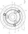
- the present invention aims to provide a high performance power generation apparatus which comprises a first rotary member 10, a second rotary member 20 and a housing 40.
- the second rotary member 20 has a first housing chamber 21 to hold the first rotary member 10.
- the housing 40 has a second housing chamber 41 to hold the secondary rotary member 20 and a lid 50 to couple on each of two ends thereof.
- the lid 50 has at least one pin 501.
- the first rotary member 10 and second rotary member 20 can be held inside the housing 40 through the two lids 50.
- the second rotary member 20 and housing 40 have respectively at least one first holding groove 26 and at least one second holding groove 44 corresponding to each other to hold an airtight ring 45.
- the secondary rotary member 20 further has a plurality of bearings 24 located on the perimeter to provide spinning support of the second rotary member 20 in the housing 40.
- the first rotary member 10 has a spindle 11 and a rotor 12 fastened to the spindle 11.
- the spindle 11 has a first gear 111 coupled thereon.
- the rotor 12 has a first electromagnetic portion 121.
- the second rotary member 20 has an internal gear ring 22 and a second electromagnetic portion 23 corresponding to the first electromagnetic portion 121.
- the first electromagnetic portion 121 is an induction coil
- the second electromagnetic portion 23 is a magnet, but they are not the limitation of the invention, and can be selectively switched according to design requirements.
- the first gear 111 and internal gear ring 22 further are interposed by at least one transmission gear 30 which is rotatably mounted onto the pin 501 to engage with the first gear 111 and internal gear ring 22.
- the transmission gear 30 includes three sets evenly spaced from each other at a same angle of 120 degrees. The number and angular positioning of the transmission gear 30 previously discussed merely serve as an example, but not the limitation of the invention. Thus forms the main structure of the invention.
- the first rotary member 10 and second rotary member 20 spin against each other that results in alterations of magnetic field to generate electric power.
- the spindle 11 can be driven by an internal combustion engine (such as a diesel engine or a gasoline engine), a steam engine, wind power or hydraulic power or the like.
- the spindle 11 drives the rotor 12 and first gear 111 to generate a first spinning displacement (in the clockwise direction as shown in the drawing).
- the first gear 111 drives the transmission gear 30 spinning in the opposite direction (in the counterclockwise direction as shown in the drawing).
- the internal gear ring 22 of the second rotary member 20 is driven so that the second rotary member 20 generates a second spinning displacement (in the counterclockwise direction as shown in the drawing) opposite to the first spinning displacement.
- the first electromagnetic portion 121 of the first rotary member 10 and second electromagnetic portion 23 of the second rotary member 20 interact with each other to generate electromagnetic effect, and the first electromagnetic portion 121 generates current in the magnetic field of the second electromagnetic portion 23 because of their relative motion.
- the second rotary member 20 can get more electric power output because of spinning against the first rotary member 10.
- the relative speed is faster when the teeth number of the first gear 111 approximates closer to the internal gear ring 22, and the corresponding output power also is greater.
- the second rotary member 20 has fluid guiding channels 25 formed thereon.
- the fluid guiding channels 25 are formed in a helical manner to surround the surface of the second rotary member 20.
- the housing 40 has at least one fluid inlet 42 and at least one fluid outlet 43 communicating with the fluid guiding channels 25.
- the fluid guiding channels 25 also spin and external cooling fluid enters the fluid guiding channels 25 via the fluid inlet 42 and discharges via the fluid outlet 43 so that a cooling flow is generated in the fluid guiding channels 25 to provide desired cooling effect for the second rotary member 20.
- the cooling fluid can be cooling gas, cooling oil or other cooling liquids.
- the fluid inlet 42 and fluid outlet 43 further may include a filter inside to filter out impurities.
- the invention by providing the first gear 111 on the first rotary member 10 and internal gear ring 22 on the second rotary member 22, and the transmission gear 30 between the first gear 111 and internal gear ring 22, can make the second rotary member 20 spinning against the first rotary member 10 in the opposite direction, thereby increase the relative spinning speed between them and enhance power generation. Due to the transmission gear 30 is located between the first and second rotary members 10 and 20 to change spinning direction, space can be saved, and also can be immediately adopted on existing power generators to realize economic benefit and improve practicality.
Landscapes
- Engineering & Computer Science (AREA)
- Power Engineering (AREA)
- Connection Of Motors, Electrical Generators, Mechanical Devices, And The Like (AREA)
Applications Claiming Priority (1)
| Application Number | Priority Date | Filing Date | Title |
|---|---|---|---|
| TW100105194A TWI462437B (zh) | 2011-02-17 | 2011-02-17 | High performance power generation |
Publications (2)
| Publication Number | Publication Date |
|---|---|
| EP2490321A2 true EP2490321A2 (de) | 2012-08-22 |
| EP2490321A3 EP2490321A3 (de) | 2016-06-01 |
Family
ID=45655541
Family Applications (1)
| Application Number | Title | Priority Date | Filing Date |
|---|---|---|---|
| EP12154754.1A Withdrawn EP2490321A3 (de) | 2011-02-17 | 2012-02-09 | Hochleistungs-Stromerzeugungsvorrichtung |
Country Status (3)
| Country | Link |
|---|---|
| US (1) | US9071095B2 (de) |
| EP (1) | EP2490321A3 (de) |
| TW (1) | TWI462437B (de) |
Cited By (9)
| Publication number | Priority date | Publication date | Assignee | Title |
|---|---|---|---|---|
| EP3012143A1 (de) * | 2014-10-20 | 2016-04-27 | Chung-Ming Chou | Stromerzeugungsvorrichtung |
| CN106655669A (zh) * | 2017-01-22 | 2017-05-10 | 湖南电将军新能源有限公司 | 一种基于双转机构的发电装置 |
| CN106712198A (zh) * | 2017-01-22 | 2017-05-24 | 湖南电将军新能源有限公司 | 一种基于移动电源的通信方法 |
| CN106787438A (zh) * | 2017-01-22 | 2017-05-31 | 湖南电将军新能源有限公司 | 一种发电方法 |
| CN106787076A (zh) * | 2017-01-22 | 2017-05-31 | 湖南电将军新能源有限公司 | 一种内置双转发电装置的移动电源 |
| CN106787075A (zh) * | 2017-01-22 | 2017-05-31 | 湖南电将军新能源有限公司 | 一种具有无线通信模块的移动电源 |
| CN107240941A (zh) * | 2017-01-22 | 2017-10-10 | 湖南电将军新能源有限公司 | 一种移动电源的分区充电方法 |
| FR3068536A1 (fr) * | 2017-07-03 | 2019-01-04 | Dcns | Moteur contrarotatif a stator tournant notamment pour un engin sous-marin et engin sous-marin correspondant |
| CN114865816A (zh) * | 2022-06-10 | 2022-08-05 | 诺丁汉大学卓越灯塔计划(宁波)创新研究院 | 一种正反转双转子能量采集器 |
Families Citing this family (3)
| Publication number | Priority date | Publication date | Assignee | Title |
|---|---|---|---|---|
| CN106786972B (zh) * | 2017-01-22 | 2023-11-28 | 湖南电将军新能源有限公司 | 一种分区充电式移动电源 |
| CN114243985B (zh) * | 2021-12-24 | 2022-11-08 | 江苏航天动力机电有限公司 | 一种具有翻转式主动防护散热机构的永磁电机 |
| US12506389B1 (en) | 2024-08-14 | 2025-12-23 | Ramkumar Chokkalingam | Bidirectional rotor device for electromechanical energy conversion and method thereof |
Citations (3)
| Publication number | Priority date | Publication date | Assignee | Title |
|---|---|---|---|---|
| TW200409438A (en) | 2002-11-28 | 2004-06-01 | li-ping Jiang | High efficiency generator |
| TW201025796A (en) | 2008-12-19 | 2010-07-01 | Sweet Corp E | Power generator apparatus for raising power-generating efficiency |
| TW201027884A (en) | 2009-01-14 | 2010-07-16 | Hong-Chang Huang | Generator |
Family Cites Families (17)
| Publication number | Priority date | Publication date | Assignee | Title |
|---|---|---|---|---|
| DE583411C (de) * | 1931-06-12 | 1934-01-22 | Johann Wickner | Elektrische Wechselstrommaschine, deren Feld- und Ankerwicklung gegeneinander umlaufen und durch Getriebeglieder miteinander verbunden sind |
| KR930005967B1 (ko) * | 1989-08-26 | 1993-06-30 | 나종오 | 변속장치 및 고속장치로 이루어진 연속자동 변속장치 |
| US5089734A (en) * | 1990-11-26 | 1992-02-18 | Ramsingh Bickraj | Dual rotary ac generator |
| JPH10127012A (ja) * | 1996-10-15 | 1998-05-15 | Sony Corp | 発電装置 |
| US6252317B1 (en) * | 1998-03-04 | 2001-06-26 | Edward N. Scheffer | Electric motor with ring rotor passing through coils |
| KR20020016681A (ko) * | 2000-08-26 | 2002-03-06 | 근 석 장 | 풍력을 이용한 동력 발생 장치 |
| US6608397B2 (en) * | 2000-11-09 | 2003-08-19 | Ntn Corporation | Wind driven electrical power generating apparatus |
| FR2817405B1 (fr) * | 2000-11-24 | 2004-09-10 | Leroy Somer Moteurs | Stator de machine tournante |
| JP4266740B2 (ja) * | 2003-07-28 | 2009-05-20 | 株式会社ソディック | コアレス交流リニアモータ |
| CN102705162B (zh) * | 2003-08-12 | 2014-10-22 | 纳博特斯克株式会社 | 风力发电机的偏摆驱动装置 |
| US7215037B2 (en) * | 2004-11-19 | 2007-05-08 | Saverio Scalzi | Protective wind energy conversion chamber |
| US7227276B2 (en) * | 2005-08-08 | 2007-06-05 | Caiozza Joseph C | Wind driven electric generator apparatus |
| TWM326582U (en) | 2007-06-20 | 2008-02-01 | Hi Energy Technology Co Ltd | Direct-driving generator of outer rotating |
| US7964978B1 (en) * | 2008-10-06 | 2011-06-21 | Douglas Weissmann | Wind turbine having a blade ring using magnetic levitation |
| CN101364759A (zh) * | 2008-10-06 | 2009-02-11 | 丁行 | 双转子行星差速发电机 |
| TWI448047B (zh) * | 2009-02-24 | 2014-08-01 | Sunco Invest Ltd | 多級可變磁阻電動機/發電機、其設計方法及控制邏輯與電路控制系統 |
| TWM381221U (en) * | 2009-11-17 | 2010-05-21 | Chao-Yin Hsiao | Internal and external rotor of coaxial generator and coaxial motor |
-
2011
- 2011-02-17 TW TW100105194A patent/TWI462437B/zh not_active IP Right Cessation
-
2012
- 2012-02-09 EP EP12154754.1A patent/EP2490321A3/de not_active Withdrawn
- 2012-02-15 US US13/397,006 patent/US9071095B2/en not_active Expired - Fee Related
Patent Citations (3)
| Publication number | Priority date | Publication date | Assignee | Title |
|---|---|---|---|---|
| TW200409438A (en) | 2002-11-28 | 2004-06-01 | li-ping Jiang | High efficiency generator |
| TW201025796A (en) | 2008-12-19 | 2010-07-01 | Sweet Corp E | Power generator apparatus for raising power-generating efficiency |
| TW201027884A (en) | 2009-01-14 | 2010-07-16 | Hong-Chang Huang | Generator |
Cited By (12)
| Publication number | Priority date | Publication date | Assignee | Title |
|---|---|---|---|---|
| EP3012143A1 (de) * | 2014-10-20 | 2016-04-27 | Chung-Ming Chou | Stromerzeugungsvorrichtung |
| CN106655669A (zh) * | 2017-01-22 | 2017-05-10 | 湖南电将军新能源有限公司 | 一种基于双转机构的发电装置 |
| CN106712198A (zh) * | 2017-01-22 | 2017-05-24 | 湖南电将军新能源有限公司 | 一种基于移动电源的通信方法 |
| CN106787438A (zh) * | 2017-01-22 | 2017-05-31 | 湖南电将军新能源有限公司 | 一种发电方法 |
| CN106787076A (zh) * | 2017-01-22 | 2017-05-31 | 湖南电将军新能源有限公司 | 一种内置双转发电装置的移动电源 |
| CN106787075A (zh) * | 2017-01-22 | 2017-05-31 | 湖南电将军新能源有限公司 | 一种具有无线通信模块的移动电源 |
| CN107240941A (zh) * | 2017-01-22 | 2017-10-10 | 湖南电将军新能源有限公司 | 一种移动电源的分区充电方法 |
| CN106787076B (zh) * | 2017-01-22 | 2019-04-30 | 湖南电将军新能源有限公司 | 一种内置双转发电装置的移动电源 |
| CN106712198B (zh) * | 2017-01-22 | 2020-01-07 | 湖南电将军新能源有限公司 | 一种基于移动电源的通信方法 |
| CN107240941B (zh) * | 2017-01-22 | 2020-01-07 | 湖南电将军新能源有限公司 | 一种移动电源的分区充电方法 |
| FR3068536A1 (fr) * | 2017-07-03 | 2019-01-04 | Dcns | Moteur contrarotatif a stator tournant notamment pour un engin sous-marin et engin sous-marin correspondant |
| CN114865816A (zh) * | 2022-06-10 | 2022-08-05 | 诺丁汉大学卓越灯塔计划(宁波)创新研究院 | 一种正反转双转子能量采集器 |
Also Published As
| Publication number | Publication date |
|---|---|
| US20120212084A1 (en) | 2012-08-23 |
| TW201236323A (en) | 2012-09-01 |
| TWI462437B (zh) | 2014-11-21 |
| EP2490321A3 (de) | 2016-06-01 |
| US9071095B2 (en) | 2015-06-30 |
Similar Documents
| Publication | Publication Date | Title |
|---|---|---|
| US9071095B2 (en) | High performance power generation apparatus | |
| US7646126B2 (en) | Permanent-magnet switched-flux machine | |
| CN209731123U (zh) | 具有分体式壳体的模块式电机 | |
| KR102623591B1 (ko) | 돌극형 하이브리드 여자 모터 | |
| CN104393727B (zh) | 径向磁场电磁行星齿轮变速器 | |
| CN102510191B (zh) | 横向-轴径向磁通结构无刷复合式永磁电机 | |
| WO2013008838A1 (ja) | 発電装置 | |
| WO2009034302A1 (en) | Magnetic flux conducting unit | |
| US20220181920A1 (en) | End winding flux motor | |
| CN101534031A (zh) | 悬浮叶轮式直流电机 | |
| CN202444390U (zh) | 一种盘式低速大转矩永磁游标电机 | |
| CN105553148B (zh) | 一种转轴偏转式永磁发电机 | |
| EP4270739A1 (de) | Magnetisch gegetriebete elektrische maschine und stromerzeugungssystem | |
| CN102361380B (zh) | 横向-径向磁通结构无刷复合式永磁电机 | |
| CN202405975U (zh) | 一种用于低速大转矩的永磁游标电机 | |
| CN105207384B (zh) | 一种双绕组高功率密度混合励磁永磁电动机 | |
| EP3644482B1 (de) | Elektrisches stromerzeugungssystem | |
| CN103090082A (zh) | 密封阀开关电机 | |
| CN104935131A (zh) | 一种内散热复合磁通切换永磁电机 | |
| CN105720766B (zh) | 拖拉机带散热器风扇的电动发电一体机 | |
| CN109274247A (zh) | 一种永磁变速箱 | |
| CN102651595B (zh) | 高效能发电装置 | |
| CN102377299B (zh) | 横向-轴向磁通结构无刷复合式永磁电机 | |
| CN201197098Y (zh) | 悬浮叶轮式直流电机 | |
| CN202435227U (zh) | 旋转往复式直线发电机 |
Legal Events
| Date | Code | Title | Description |
|---|---|---|---|
| PUAI | Public reference made under article 153(3) epc to a published international application that has entered the european phase |
Free format text: ORIGINAL CODE: 0009012 |
|
| AK | Designated contracting states |
Kind code of ref document: A2 Designated state(s): AL AT BE BG CH CY CZ DE DK EE ES FI FR GB GR HR HU IE IS IT LI LT LU LV MC MK MT NL NO PL PT RO RS SE SI SK SM TR |
|
| AX | Request for extension of the european patent |
Extension state: BA ME |
|
| PUAL | Search report despatched |
Free format text: ORIGINAL CODE: 0009013 |
|
| AK | Designated contracting states |
Kind code of ref document: A3 Designated state(s): AL AT BE BG CH CY CZ DE DK EE ES FI FR GB GR HR HU IE IS IT LI LT LU LV MC MK MT NL NO PL PT RO RS SE SI SK SM TR |
|
| AX | Request for extension of the european patent |
Extension state: BA ME |
|
| RIC1 | Information provided on ipc code assigned before grant |
Ipc: H02K 9/193 20060101ALN20160428BHEP Ipc: H02K 7/18 20060101ALI20160428BHEP Ipc: H02K 7/08 20060101ALI20160428BHEP Ipc: H02K 16/00 20060101ALI20160428BHEP Ipc: H02K 9/19 20060101ALI20160428BHEP Ipc: H02K 5/20 20060101ALN20160428BHEP Ipc: H02K 7/116 20060101AFI20160428BHEP |
|
| STAA | Information on the status of an ep patent application or granted ep patent |
Free format text: STATUS: REQUEST FOR EXAMINATION WAS MADE |
|
| 17P | Request for examination filed |
Effective date: 20161031 |
|
| RBV | Designated contracting states (corrected) |
Designated state(s): AL AT BE BG CH CY CZ DE DK EE ES FI FR GB GR HR HU IE IS IT LI LT LU LV MC MK MT NL NO PL PT RO RS SE SI SK SM TR |
|
| STAA | Information on the status of an ep patent application or granted ep patent |
Free format text: STATUS: EXAMINATION IS IN PROGRESS |
|
| 17Q | First examination report despatched |
Effective date: 20170612 |
|
| STAA | Information on the status of an ep patent application or granted ep patent |
Free format text: STATUS: THE APPLICATION HAS BEEN WITHDRAWN |
|
| 18W | Application withdrawn |
Effective date: 20170824 |