EP2490435A2 - Système de traitement de signal TV analogique numérisé - Google Patents
Système de traitement de signal TV analogique numérisé Download PDFInfo
- Publication number
- EP2490435A2 EP2490435A2 EP12168176A EP12168176A EP2490435A2 EP 2490435 A2 EP2490435 A2 EP 2490435A2 EP 12168176 A EP12168176 A EP 12168176A EP 12168176 A EP12168176 A EP 12168176A EP 2490435 A2 EP2490435 A2 EP 2490435A2
- Authority
- EP
- European Patent Office
- Prior art keywords
- signal
- unit
- control unit
- quality indicator
- video
- Prior art date
- Legal status (The legal status is an assumption and is not a legal conclusion. Google has not performed a legal analysis and makes no representation as to the accuracy of the status listed.)
- Withdrawn
Links
- 238000011084 recovery Methods 0.000 claims abstract description 21
- 230000005236 sound signal Effects 0.000 claims description 27
- 238000005070 sampling Methods 0.000 claims description 12
- 230000004044 response Effects 0.000 claims description 6
- 238000001228 spectrum Methods 0.000 description 15
- 101100368149 Mus musculus Sync gene Proteins 0.000 description 11
- 230000008859 change Effects 0.000 description 2
- 239000002131 composite material Substances 0.000 description 2
- 230000000694 effects Effects 0.000 description 2
- 230000004048 modification Effects 0.000 description 2
- 238000012986 modification Methods 0.000 description 2
- 230000001360 synchronised effect Effects 0.000 description 2
- 241001502050 Acis Species 0.000 description 1
- 101000959126 Xenopus laevis Peptidyl-alpha-hydroxyglycine alpha-amidating lyase B Proteins 0.000 description 1
- 239000004973 liquid crystal related substance Substances 0.000 description 1
- 238000000034 method Methods 0.000 description 1
- 230000008569 process Effects 0.000 description 1
- 230000009467 reduction Effects 0.000 description 1
Images

Classifications
-
- H—ELECTRICITY
- H04—ELECTRIC COMMUNICATION TECHNIQUE
- H04N—PICTORIAL COMMUNICATION, e.g. TELEVISION
- H04N5/00—Details of television systems
- H04N5/44—Receiver circuitry for the reception of television signals according to analogue transmission standards
- H04N5/455—Demodulation-circuits
-
- H—ELECTRICITY
- H04—ELECTRIC COMMUNICATION TECHNIQUE
- H04N—PICTORIAL COMMUNICATION, e.g. TELEVISION
- H04N21/00—Selective content distribution, e.g. interactive television or video on demand [VOD]
- H04N21/40—Client devices specifically adapted for the reception of or interaction with content, e.g. set-top-box [STB]; Operations thereof
- H04N21/41—Structure of client; Structure of client peripherals
- H04N21/426—Internal components of the client ; Characteristics thereof
- H04N21/42607—Internal components of the client ; Characteristics thereof for processing the incoming bitstream
- H04N21/4263—Internal components of the client ; Characteristics thereof for processing the incoming bitstream involving specific tuning arrangements, e.g. two tuners
- H04N21/42638—Internal components of the client ; Characteristics thereof for processing the incoming bitstream involving specific tuning arrangements, e.g. two tuners involving a hybrid front-end, e.g. analog and digital tuners
-
- H—ELECTRICITY
- H04—ELECTRIC COMMUNICATION TECHNIQUE
- H04N—PICTORIAL COMMUNICATION, e.g. TELEVISION
- H04N21/00—Selective content distribution, e.g. interactive television or video on demand [VOD]
- H04N21/40—Client devices specifically adapted for the reception of or interaction with content, e.g. set-top-box [STB]; Operations thereof
- H04N21/43—Processing of content or additional data, e.g. demultiplexing additional data from a digital video stream; Elementary client operations, e.g. monitoring of home network or synchronising decoder's clock; Client middleware
- H04N21/438—Interfacing the downstream path of the transmission network originating from a server, e.g. retrieving encoded video stream packets from an IP network
- H04N21/4382—Demodulation or channel decoding, e.g. QPSK demodulation
-
- H—ELECTRICITY
- H04—ELECTRIC COMMUNICATION TECHNIQUE
- H04N—PICTORIAL COMMUNICATION, e.g. TELEVISION
- H04N5/00—Details of television systems
- H04N5/14—Picture signal circuitry for video frequency region
- H04N5/148—Video amplifiers
-
- H—ELECTRICITY
- H04—ELECTRIC COMMUNICATION TECHNIQUE
- H04N—PICTORIAL COMMUNICATION, e.g. TELEVISION
- H04N5/00—Details of television systems
- H04N5/14—Picture signal circuitry for video frequency region
- H04N5/20—Circuitry for controlling amplitude response
-
- H—ELECTRICITY
- H04—ELECTRIC COMMUNICATION TECHNIQUE
- H04N—PICTORIAL COMMUNICATION, e.g. TELEVISION
- H04N5/00—Details of television systems
- H04N5/14—Picture signal circuitry for video frequency region
- H04N5/20—Circuitry for controlling amplitude response
- H04N5/205—Circuitry for controlling amplitude response for correcting amplitude versus frequency characteristic
-
- H—ELECTRICITY
- H04—ELECTRIC COMMUNICATION TECHNIQUE
- H04N—PICTORIAL COMMUNICATION, e.g. TELEVISION
- H04N5/00—Details of television systems
- H04N5/14—Picture signal circuitry for video frequency region
- H04N5/21—Circuitry for suppressing or minimising disturbance, e.g. moiré or halo
-
- H—ELECTRICITY
- H04—ELECTRIC COMMUNICATION TECHNIQUE
- H04N—PICTORIAL COMMUNICATION, e.g. TELEVISION
- H04N5/00—Details of television systems
- H04N5/14—Picture signal circuitry for video frequency region
- H04N5/21—Circuitry for suppressing or minimising disturbance, e.g. moiré or halo
- H04N5/213—Circuitry for suppressing or minimising impulsive noise
-
- H—ELECTRICITY
- H04—ELECTRIC COMMUNICATION TECHNIQUE
- H04N—PICTORIAL COMMUNICATION, e.g. TELEVISION
- H04N5/00—Details of television systems
- H04N5/44—Receiver circuitry for the reception of television signals according to analogue transmission standards
- H04N5/4446—IF amplifier circuits specially adapted for B&W TV
-
- H—ELECTRICITY
- H04—ELECTRIC COMMUNICATION TECHNIQUE
- H04N—PICTORIAL COMMUNICATION, e.g. TELEVISION
- H04N5/00—Details of television systems
- H04N5/44—Receiver circuitry for the reception of television signals according to analogue transmission standards
- H04N5/46—Receiver circuitry for the reception of television signals according to analogue transmission standards for receiving on more than one standard at will
-
- H—ELECTRICITY
- H04—ELECTRIC COMMUNICATION TECHNIQUE
- H04N—PICTORIAL COMMUNICATION, e.g. TELEVISION
- H04N5/00—Details of television systems
- H04N5/44—Receiver circuitry for the reception of television signals according to analogue transmission standards
- H04N5/52—Automatic gain control
-
- H—ELECTRICITY
- H04—ELECTRIC COMMUNICATION TECHNIQUE
- H04N—PICTORIAL COMMUNICATION, e.g. TELEVISION
- H04N5/00—Details of television systems
- H04N5/44—Receiver circuitry for the reception of television signals according to analogue transmission standards
- H04N5/60—Receiver circuitry for the reception of television signals according to analogue transmission standards for the sound signals
- H04N5/62—Intercarrier circuits, i.e. heterodyning sound and vision carriers
Definitions
- the invention relates to an analog television signal processing system, and more particularly to digitized analog television signal processing systems capable of fine tuning the demodulation process of the television signal according to side information resulting from signal decoding.
- a television is a widely used telecommunication system for broadcasting and receiving moving pictures and sound over a distance.
- the television set has become a common household communications device in homes and institutions as a source of entertainment and news.
- the International Telecommunications Union ITU
- Each monochrome TV system is assigned a letter designation (e.g., B, D, G, H, I, K, L, M, and N), which defines the characteristics of a TV signal such as video/sound modulation scheme, channel bandwidth, sound offset, frame rate, etc.
- NTSC National Television System Committee
- SECAM Sequential Color with Memory
- PAL Phase Alternating Line
- NTSC National Television System Committee
- SECAM Sequential Color with Memory
- PAL Phase Alternating Line
- Analog TV systems have been established for decades, however, digital display devices, such as liquid crystal displays (LCDs) and plasma display panels (PDPs), have become more and more popular in recent years. Accordingly, the analog TV signal is being required to be converted to a digital TV signal via an analog-to-digital converter (ADC) and be displayed on an LCD, a PDP, or the similar.
- ADC analog-to-digital converter
- the invention provides a digitized analog television signal processing system.
- the digitized analog television signal processing system comprises an analog-to-digital converter, a demodulation unit, a decoding unit, and a control unit.
- the analog-to-digital converter samples a television signal comprising a video signal.
- the demodulation unit demodulates the video signal.
- the decoding unit decodes the demodulated video signal.
- the control unit adjusts the demodulation unit according to a signal quality indicator generated during and/or after the decoding of the decoding unit.
- the demodulation unit further comprises a carrier recovery unit configured to lock a video carrier of the video signal at an intermediate frequency, and the control unit can make a loop bandwidth of the carrier recovery unit controlled according to the signal quality indicator.
- the television signal can further comprise a sound signal
- the digitized analog television signal processing system can further comprise a sound processing unit to demodulate and/or decode the sound signal.
- the signal quality indicator can be further generated during and/or after the processing of the sound processing unit.
- the demodulation unit can further comprise an automatic gain controller, a filter bank, and an equalizer.
- the automatic gain controller can control a dynamic range of the television signal, and the control unit can control a loop tuning speed of the automatic gain controller according to the signal quality indicator.
- the filter bank can separate the video signal and the sound signal from the television signal, and the control unit can adjust a bandwidth or a passband center of the filter bank according to the signal quality indicator.
- the equalizer can shape a frequency response of the television signal, and the control unit can control the equalizer according to the signal quality indicator.
- FIG. 1 is a typical form of a power spectrum density (PSD) of a TV channel
- FIG. 2 is an embodiment of a digitized analog TV signal processing system 200 according to the invention.
- FIG. 3A-3C shows an example of different sampling rates
- FIG. 4A shows an example of a standard CVBS signal in time domain
- FIG. 4B and 4C shows two possible kinds of nonstandard reference signals
- FIG. 5A shows an example of a baseband CVBS spectrum with a low SNR
- FIG. 5B shows another example of the baseband CVBS spectrum with a high SNR.
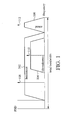
- FIG. 1 is a typical form of a power spectrum density (PSD) of a TV channel.
- a TV channel occupies a total bandwidth such as 6MHz for the NTSC standard and 8MHz for the PAL and SECAM standards.
- the TV signal comprises a sound signal 106 and a video signal comprising a luminance signal 102 and a chrominance signal 104.
- the luminance signal 102 contains brightness information of the video signal, while the chrominance signal 104 contains color information of the video signal.
- the luminance signal 102 which is amplitude-modulated with a video carrier 108 (also referred to as luminance carrier), is transmitted above the lower bound of the channel.
- a video carrier 108 also referred to as luminance carrier
- the luminance signal 102 Like most amplitude modulated signals, the luminance signal 102 generates two sidebands, one above the video carrier 108 and the other below. The entire upper sideband is transmitted, but only part of the lower sideband, known as a vestigial sideband, is transmitted.
- the chrominance signal 104 is quadrature-amplitude-modulated with a suppressed color carrier 110 (also referred to as chrominance carrier).
- the highest part of the channel contains the sound signal 106, which is frequency-modulated with a sound carrier 106, making it compatible with the sound signals broadcasted by FM radio stations.
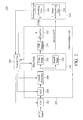
- FIG. 2 is an embodiment of a digitized analog TV signal processing system 200 according to the invention.
- the digitized analog TV signal processing system 200 comprises an analog-to-digital converter (ADC) 202, a demodulation unit 203, a processing unit 214, and a control unit 216.
- the digitized analog TV signal processing system 200 can further comprise a tuner (not shown) configured to shift an analog TV signal modulated with a radio-frequency (RF) video carrier to an intermediate-frequency (IF) TV signal comprising a video signal and a sound signal, wherein the IF is much lower than the RF carrier.
- RF radio-frequency
- IF intermediate-frequency
- the demodulation unit 203 comprising an automatic gain controller (AGC) unit 204, a carrier recovery unit 206, a filter bank 208, a vestigial sideband (VSB) demodulator 210, and an equalizer 212, can demodulate the video signal as a composite video baseband signal (CVBS).
- AGC automatic gain controller
- VSB vestigial sideband
- CVBS composite video baseband signal
- the demodulation unit 203 demodulates the TV signal according to the modulation scheme of a monochrome TV system (e.g., system B or system N)
- the processing unit 214 decodes the video signal and demodulates and/or decodes the sound signal according to an analog color TV system (e.g. NTSC, SECAM, or PAL).
- an analog color TV system e.g. NTSC, SECAM, or PAL
- the demodulation unit 203 may further generate a signal quality indicator during and/or the demodulation and forward it to the control unit 216.
- the ADC 202 performs IF-sampling and can sample the IF TV signal at a sampling rate to convert the IF TV signal to a digital form.
- the AGC unit 204 can adjust the dynamic range of the IF TV signal. For example, the AGC unit 204 can calculate detect the peak level of the input IF TV signal and then feed it back to adjust the gain to an appropriate level, thus prevents IF signal clipping after ADC.
- the carrier recovery unit 206 may be a phase locked loop (PLL) circuit that locks frequency and phase of the video carrier for further synchronous demodulation.
- PLL phase locked loop
- the filter bank 208 may comprise a video filter 218 and a sound filter 220 to separate the video signal and the sound signal from the IF TV signal, and forward the video signal to the VSB demodulator 210 and forward the sound signal (i.e., 2nd sound IF) to the sound processing unit 214.
- the video filter 218 and the sound filter 220 are both band-pass filter (BPF) but with different passband centers that can filter out undesired frequency components and separate the video and sound signals.
- the VSB demodulator 210 can convert the vestigial sideband signal (i.e. the luminance signal of the video signal) to a double-sideband signal, which is called the composite video baseband signal (CVBS).
- the equalizer 212 can shape the frequency response of CVBS to alleviate possible waveform overshoot/distortion introduced by TV transmitter, channel, and receiver.
- the CVBS is then fed to the processing unit 214. It is noted that the order of the filter bank 208, the VSB demodulator 210, and the equalizer 212 can be exchanged.
- the processing unit 214 can comprise a decoding unit 222 and a sound processing unit 224 to decode the video signal and demodulate and/or decode the sound signal, according to a standard type such as the NTSC standard , the SECAM standard, or the PAL standard.
- the CVBS is a video signal comprising a chrominance signal, a luminance signal, a color burst, and horizontal and vertical sync pulses.
- the color burst is a signal used to keep the color subcarrier synchronized in the chrominance signal. By synchronizing an oscillator with the color burst at the beginning of each scan line, a television receiver is able to restore the suppressed carrier of the chrominance signal, and in turn decode the color information.
- the horizontal sync pulse is used to indicate the beginning of a scan line
- the vertical sync pulse is used to indicate the beginning of a frame.
- the decoding unit 222 can decode the CVBS according to the used standard type and the signal levels of the color burst and the sync pulses, and may measure the signal quality (such as the signal-to-noise ratio (SNR) estimation of CVBS or non-standard signal format indication).
- SNR signal-to-noise ratio
- the sound processing unit 224 can recover the sound carrier of the sound signal, demodulate/decode the sound signal, and may measure the signal quality of the sound signal.
- the processing unit 214 may further generate a signal quality indicator according to the decoded video signal, video signal under decoding, processed sound signal, sound signal under processing, or a combination thereof, and forward the signal quality indicator to the control unit 216.
- the signal quality indicator may also be generated by the control unit 216 according to the decoded video signal, video signal under decoding, the demodulated video signal, the video signal under demodulation, processed sound signal, sound signal under processing, or a combination thereof, which are transmitted to the control unit 216 by the demodulation unit 203 or the processing unit 214.
- the control unit 216 can generate one or more feedback signals to control the ADC 202, the AGC unit 204, the carrier recovery unit 206, the filter bank 208, the equalizer 212, and the processing unit 214 according to the signal quality indicator.
- the control unit 216 may be implemented via hardware, software, firmware, or a combination thereof.
- the control unit 216 can control the sampling rate of the ADC 202 to prevent adjacent channel interference (ACI).
- FIGs. 3A-3C shows an example of different sampling rates.
- FIG. 3A is the original IF spectrum comprising a video signal 302, a sound signal 304 of a TV channel, and ACIs 306, 308, and 310.
- the interferences 306-310 does not interfere with the video signal 302 and the sound signal 304, because the spectrum of the TV channel is not overlapped with the interferences 306-310.
- FIG. 3B shows an IF spectrum sampled with a sampling rate F1, wherein the interferences 308-310 are overlapped with the spectrum of the video signal 302 because of an aliasing effect.
- the processing unit 214 when the processing unit 214 detects that the signal quality of the video signal is bad, the problem may result from the aliasing effect and the processing unit 214 may output a signal quality indicator to the control unit 216 to generate a feedback signal to the ADC 202 to change the sampling rate.
- the processing unit 214 will check if the signal quality of the video signal is improved; if not, the sampling rate of the ADC 202 will be changed several times until the processing unit 214 detects the best signal quality of the video signal.
- FIG. 3C shows an IF spectrum sampled with another sampling rate F2 after the ADC 202 receives the feedback signal, and the interference 306-310 are separate from the spectrum of the video signal 302 and the sound signal 304. It should be noted that the sampling rate F2 may be larger or less than the sample rate F1.
- the control unit 216 can control the AGC unit 204 to dynamically adjust the reference signal levels.
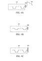
- FIG. 4A shows an example of a standard CVBS in time domain.
- the signal levels of sync pulses 402 e.g., horizontal or vertical sync pulses
- a color burst 404 can be used as reference signals for the AGC unit 204 to compensate for the signal level of the video signal 406, since the signal levels of the sync pulses 402 and the color burst 404 have known signal levels.
- the signal levels of the sync pulse 402 and the color burst 404 may not be transmitted as the same as the standard reference signals.
- FIGs . 4B and 4C shows two possible kinds of nonstandard reference signals. Referring to FIG.
- the color burst 404 has a standard signal level as FIG. 4A but the sync pulses 402 have nonstandard signal levels less than those of the sync pulses in FIG. 4A .
- the sync pulses 402 have standard signal levels as FIG. 4A but the color burst 404 has a nonstandard signal level larger than that of the color burst in FIG. 4A .
- the processing unit 214 detects that the signal levels of the reference signals are different from the standard ones, the processing unit 214 can feedback a signal quality indicator indicating that the reference signals are not standard signals to the control unit 216.
- the control unit 216 can generate a signal to the AGC unit 204 to modify the target reference signal levels of the reference signals.
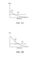
- the signal quality indicator generated by the processing unit 214 can comprise a signal-to-noise ratio (SNR) of the video signal.
- SNR signal-to-noise ratio
- FIG. 5A shows an example of a baseband CVBS spectrum 502 with a low SNR corresponding to a noise spectrum 504, while FIG. 5B shows another example of the baseband CVBS spectrum 502 with a high SNR corresponding to the noise spectrum 504. It is known in the art that the CVBS is mostly in the low-frequency band, while the noise spectrum is uniformly distributed. Accordingly, referring to FIG. 2 and FIG.
- the control unit 216 can generate a feedback signal to the video filter 218 to reduce the bandwidth of the video filter 218 (and/or generate another feedback signal to the equalizer 212 to modify the frequency response of the equalizer 212) to reject more high-frequency noise at the expense of the high-frequency component of the CVBS signal when the SNR is lower than a first threshold.
- the control unit 216 can generate a feedback signal to the video filter 218 to increase the bandwidth of the video filter 218 (and/or generate another feedback signal to the equalizer 212 to modify the frequency response of the equalizer 212) to reserve more high-frequency component of the CVBS when the SNR is higher than a second threshold.
- the second threshold can be larger than the first threshold to ensure that the SNR is good enough.
- the control unit 216 can output a feedback signal to the AGC unit 204 to lower the loop tuning speed of the AGC unit 204 and/or output another feedback signal to the carrier recovery unit 206 to reduce the loop bandwidth of the carrier recovery unit 206 when the SNR is lower than a third threshold.
- control unit 216 can output a feedback signal to the AGC unit 204 to increase the loop tuning speed of the AGC unit 204 and/or output a feedback signal to the carrier recovery unit 206 to increase the loop bandwidth of the carrier recovery unit 206 when the SNR of the video signal 502 is larger than a fourth threshold.
- the fourth threshold can be larger than the third threshold to ensure that the SNR is good enough.
- the signal quality indicator generated by the processing unit 214 can also comprise a SNR of the sound signal.
- the control unit 216 can generate a feedback signal to the filter bank 208 (and/or generate another feedback signal to the equalizer 212) to suppress the video signal or the ACI.
- the sound carrier of the sound signal may be away from a presumed sound carrier of the standard type, and the sound filer 220 may filter out the desired sound signal because the passband center of the sound filter 220 still locks at the presumed sound carrier.
- the signal quality indicator generated by the processing unit 214 can also comprise a signal quality indicator indicating that the received sound carrier is away from the presumed sound carrier, and the control unit 216 can generate a feedback signal to the sound filter 220 to shift the passband center of the sound filter 220 to the received sound carrier.
- the decoding unit 222 may detect a waveform overshoot of the video signal.
- the processing unit 214 can output a signal quality indicator indicating the waveform overshoot to the control unit 216, and the control unit 216 can output a feedback signal to the equalizer 212 to attenuate high frequency video component to reduce the waveform overshoot, thereby preventing signal saturation of the CVBS.
- the decoding unit 222 may detect that the decoded video signal is unrecognizable or just a meaningless noise signal. This problem may result from two reasons; one is due to the false lock of the carrier recovery unit 206, and the other is due to the incorrect standard type used in the demodulation unit 203. Accordingly, the processing unit 214 can output a signal quality indicator indicating that the decoded video signal is unrecognizable to the control unit 216, and the control unit 216 can generate a feedback signal to the carrier recovery unit 206 to reset the parameters of the carrier recovery unit 206 to lock the correct IF, and/or generate another feedback signal to the demodulation unit 203 to change to another standard type (e.g. the standard type is changed to B, D, G, H, I, K, L, M, N etc).
- another standard type e.g. the standard type is changed to B, D, G, H, I, K, L, M, N etc.
- the decoding unit 222 may detect a linear distortion between the luminance signal and the chrominance signal of the decoded video signal.
- the decoding unit 222 may detect a group delay or a large energy difference between the luminance signal and the chrominance signal.
- the processing unit 214 can output a signal quality indicator indicating the group delay or the energy imbalance to the control unit 216, and the control unit 216 can output a feedback signal to the equalizer 212 to shape the frequency response of the equalizer 212 to compensate for the group delay or the energy imbalance.
- the signal quality indicator may further be generated during and/or the demodulation of the demodulation unit 203, the control unit 216 may further be configured to adjust the decoding unit 222 according to the signal quality indicator. For example, as received RF signal is weak, the decoding unit 222 may use some video noise reduction scheme to improve synchronization efficiency by RSSI (received signal strength indicator) provided by demodulation unit 203.
- RSSI received signal strength indicator
Landscapes
- Engineering & Computer Science (AREA)
- Multimedia (AREA)
- Signal Processing (AREA)
- Circuits Of Receivers In General (AREA)
- Picture Signal Circuits (AREA)
- Television Systems (AREA)
Applications Claiming Priority (2)
| Application Number | Priority Date | Filing Date | Title |
|---|---|---|---|
| US12/112,052 US8212941B2 (en) | 2008-04-30 | 2008-04-30 | Digitized analog TV signal processing system |
| EP08103934A EP2117224A3 (fr) | 2008-04-30 | 2008-05-13 | Système de traitement de signal TV analogique numérisé |
Related Parent Applications (1)
| Application Number | Title | Priority Date | Filing Date |
|---|---|---|---|
| EP08103934A Division EP2117224A3 (fr) | 2008-04-30 | 2008-05-13 | Système de traitement de signal TV analogique numérisé |
Publications (2)
| Publication Number | Publication Date |
|---|---|
| EP2490435A2 true EP2490435A2 (fr) | 2012-08-22 |
| EP2490435A3 EP2490435A3 (fr) | 2013-09-04 |
Family
ID=40379625
Family Applications (2)
| Application Number | Title | Priority Date | Filing Date |
|---|---|---|---|
| EP08103934A Ceased EP2117224A3 (fr) | 2008-04-30 | 2008-05-13 | Système de traitement de signal TV analogique numérisé |
| EP12168176.1A Withdrawn EP2490435A3 (fr) | 2008-04-30 | 2008-05-13 | Système de traitement de signal TV analogique numérisé |
Family Applications Before (1)
| Application Number | Title | Priority Date | Filing Date |
|---|---|---|---|
| EP08103934A Ceased EP2117224A3 (fr) | 2008-04-30 | 2008-05-13 | Système de traitement de signal TV analogique numérisé |
Country Status (3)
| Country | Link |
|---|---|
| US (1) | US8212941B2 (fr) |
| EP (2) | EP2117224A3 (fr) |
| CN (1) | CN101572782A (fr) |
Cited By (1)
| Publication number | Priority date | Publication date | Assignee | Title |
|---|---|---|---|---|
| US8593526B1 (en) | 2012-06-22 | 2013-11-26 | Silicon Laboratories Inc. | Apparatus for measuring noise in an analog signal |
Families Citing this family (11)
| Publication number | Priority date | Publication date | Assignee | Title |
|---|---|---|---|---|
| US8743762B2 (en) * | 2009-06-03 | 2014-06-03 | Intel Corporation | Partial DMM reception to reduce standby power |
| US9282274B2 (en) | 2009-06-22 | 2016-03-08 | Entropic Communications, Llc | System and method for reducing intra-channel interference |
| US8953098B2 (en) * | 2010-01-29 | 2015-02-10 | Mediatek Inc. | Television signal processing device and television signal processing method |
| EP2373009A3 (fr) * | 2010-03-31 | 2014-05-28 | Sony Corporation | Appareil de récepteur de signaux de télévision avec détection des signaux sonores |
| KR101260010B1 (ko) * | 2011-08-05 | 2013-05-06 | 주식회사 아이덴코아 | 보상기능을 갖는 비디오 디코딩 시스템 |
| JP5914836B2 (ja) * | 2011-09-27 | 2016-05-11 | パナソニックIpマネジメント株式会社 | 映像復調装置 |
| CN103686011A (zh) * | 2013-11-29 | 2014-03-26 | 乐视致新电子科技(天津)有限公司 | 电视信号接收模块及接收方法 |
| CN103716510B (zh) * | 2013-12-06 | 2017-12-29 | 乐视致新电子科技(天津)有限公司 | 视频信号调节模块及调节方法 |
| CN105681780B (zh) * | 2014-11-19 | 2018-06-15 | 深圳市中兴微电子技术有限公司 | 一种复合视频广播信号质量的测量方法和装置 |
| KR102327553B1 (ko) * | 2015-07-21 | 2021-11-17 | 삼성전자 주식회사 | 방송수신장치 및 그 제어방법 |
| CN114469019B (zh) * | 2022-04-14 | 2022-06-21 | 剑博微电子(深圳)有限公司 | 脉搏波信号的滤波方法、装置和计算机设备 |
Family Cites Families (36)
| Publication number | Priority date | Publication date | Assignee | Title |
|---|---|---|---|---|
| US3328719A (en) * | 1965-08-24 | 1967-06-27 | Sylvania Electric Prod | Phase-lock loop with adaptive bandwidth |
| US4189755A (en) * | 1978-03-17 | 1980-02-19 | Microdyne Corporation | Television receiver threshold extension system by means of signal-to-noise control of bandwidth |
| GB2126812B (en) | 1982-08-30 | 1986-05-08 | Rca Corp | Television sound detection system using a phase-locked loop |
| DE3569182D1 (en) * | 1985-08-27 | 1989-05-03 | Itt Ind Gmbh Deutsche | Television sound receiving circuit for at least one audio channel contained in a hf signal |
| US4918532A (en) * | 1987-03-18 | 1990-04-17 | Connor Edward O | FM receiver method and system for weak microwave television signals |
| US5128969A (en) * | 1989-08-30 | 1992-07-07 | Baghdady Elie J | Method and apparatus for diversity reception |
| FR2659508A1 (fr) * | 1990-03-09 | 1991-09-13 | Portenseigne Radiotechnique | Demodulateur de frequences a abaissement de seuil. |
| EP0470769B1 (fr) * | 1990-08-08 | 1996-04-10 | Canon Kabushiki Kaisha | Caméra vidéo électronique d'image fixe |
| US5150384A (en) * | 1990-09-28 | 1992-09-22 | Motorola, Inc. | Carrier recovery method and apparatus having an adjustable response time determined by carrier signal parameters |
| US5111160A (en) * | 1991-04-30 | 1992-05-05 | The Grass Valley Group | Clock generation circuit for multistandard serial digital video with automatic format identification |
| CA2136567C (fr) * | 1994-11-24 | 2001-01-30 | John Charles Maycock | Appareil et methode de telesurveillance de signaux video |
| CA2175860C (fr) * | 1995-06-02 | 2001-03-27 | Randall Wayne Rich | Dispositif et methode pour optimiser la qualite d'un signal capte par un recepteur radio |
| GB2303278B (en) | 1995-07-11 | 2000-04-26 | Remo Giovanni Andrea Marzolini | Improvements to demodulation systems |
| US5671253A (en) * | 1995-07-12 | 1997-09-23 | Thomson Consumer Electronics, Inc. | Apparatus for demodulating and decoding video signals encoded in different formats |
| US5986720A (en) * | 1996-05-09 | 1999-11-16 | Matsushita Electric Industrial Co., Ltd. | Mobile television receiver |
| EP0842583B1 (fr) * | 1996-06-06 | 2002-05-02 | Koninklijke Philips Electronics N.V. | Extraction de la synchronisation horizontale |
| US6005640A (en) * | 1996-09-27 | 1999-12-21 | Sarnoff Corporation | Multiple modulation format television signal receiver system |
| US6091931A (en) * | 1997-06-18 | 2000-07-18 | Lsi Logic Corporation | Frequency synthesis architecture in a satellite receiver |
| US6285401B1 (en) * | 1998-07-28 | 2001-09-04 | Thomson Licensing S.A. | Apparatus for suppressing overshoots in kinescope beam current measurement pulses |
| KR100290851B1 (ko) * | 1999-03-27 | 2001-05-15 | 구자홍 | 디지털 티브이의 영상 처리 장치 |
| US6389070B1 (en) * | 1999-03-31 | 2002-05-14 | Philips Electronics North America Corporation | Device for indicating the received signal quality in a digital television receiver |
| JP4569791B2 (ja) | 2000-05-25 | 2010-10-27 | ソニー株式会社 | 映像処理装置および方法、並びに記録媒体 |
| GB2364455A (en) * | 2000-06-30 | 2002-01-23 | Nokia Oy Ab | An efficient low-intermodulation digital video receiver |
| KR100400752B1 (ko) * | 2001-02-07 | 2003-10-08 | 엘지전자 주식회사 | 디지털 tv 수신기에서의 vsb 복조 장치 |
| AUPR585901A0 (en) * | 2001-06-21 | 2001-07-12 | Dynamic Digital Depth Resources Pty Ltd | Image processing system |
| US20030026363A1 (en) * | 2001-07-31 | 2003-02-06 | Jan Stoter | Adaptive automatic gain control |
| JP2003152572A (ja) | 2001-11-16 | 2003-05-23 | Matsushita Electric Ind Co Ltd | Fm受信機 |
| US7342981B2 (en) * | 2004-01-15 | 2008-03-11 | Ati Technologies Inc. | Digital receiver having adaptive carrier recovery circuit |
| US7508451B2 (en) * | 2004-04-30 | 2009-03-24 | Telegent Systems, Inc. | Phase-noise mitigation in an integrated analog video receiver |
| US7265792B2 (en) * | 2004-07-01 | 2007-09-04 | Xceive Corporation | Television receiver for digital and analog television signals |
| KR100604910B1 (ko) * | 2004-10-12 | 2006-07-28 | 삼성전자주식회사 | 디지털 텔레비전 수신 장치의 동기신호 검출기 및 그 방법 |
| US8102954B2 (en) * | 2005-04-26 | 2012-01-24 | Mks Instruments, Inc. | Frequency interference detection and correction |
| CN1956522A (zh) | 2005-10-28 | 2007-05-02 | 海信集团有限公司 | 增益参数的设定方法 |
| US7782401B1 (en) * | 2006-06-20 | 2010-08-24 | Kolorific, Inc. | Method and system for digital image scaling with sharpness enhancement and transient improvement |
| US20080074497A1 (en) * | 2006-09-21 | 2008-03-27 | Ktech Telecommunications, Inc. | Method and Apparatus for Determining and Displaying Signal Quality Information on a Television Display Screen |
| US8502920B2 (en) * | 2007-03-14 | 2013-08-06 | Vyacheslav Shyshkin | Method and apparatus for extracting a desired television signal from a wideband IF input |
-
2008
- 2008-04-30 US US12/112,052 patent/US8212941B2/en not_active Expired - Fee Related
- 2008-05-13 EP EP08103934A patent/EP2117224A3/fr not_active Ceased
- 2008-05-13 EP EP12168176.1A patent/EP2490435A3/fr not_active Withdrawn
- 2008-11-04 CN CN200810172380.1A patent/CN101572782A/zh active Pending
Non-Patent Citations (1)
| Title |
|---|
| None |
Cited By (1)
| Publication number | Priority date | Publication date | Assignee | Title |
|---|---|---|---|---|
| US8593526B1 (en) | 2012-06-22 | 2013-11-26 | Silicon Laboratories Inc. | Apparatus for measuring noise in an analog signal |
Also Published As
| Publication number | Publication date |
|---|---|
| EP2117224A2 (fr) | 2009-11-11 |
| US20090273714A1 (en) | 2009-11-05 |
| EP2117224A3 (fr) | 2010-02-17 |
| CN101572782A (zh) | 2009-11-04 |
| EP2490435A3 (fr) | 2013-09-04 |
| US8212941B2 (en) | 2012-07-03 |
Similar Documents
| Publication | Publication Date | Title |
|---|---|---|
| US8212941B2 (en) | Digitized analog TV signal processing system | |
| KR100313890B1 (ko) | 디지털/아날로그 겸용 티브이 수상기 | |
| US6667760B1 (en) | Receiver for digital television signals having carriers near upper frequency boundaries of TV broadcasting channels | |
| US20080075200A1 (en) | Detecting circuit, modulation scheme identifying circuit, integrated circuit, tuning device, and common multi-scheme receiving device | |
| KR100246799B1 (ko) | 단일 제 1 검출기 및 공유 고대역 중간주파수 증폭기를 갖춘 디지털 및 아날로그 텔레비젼 신호 수신기 | |
| KR20020008050A (ko) | 텔레비젼 수신 장치 | |
| CN1298605A (zh) | 多标准电视接收的数字信号处理器 | |
| US7394500B2 (en) | World wide analog television signal receiver | |
| US20050212977A1 (en) | Audio/video separator | |
| US6445425B1 (en) | Automatic fine tuning of receiver for digital television signals | |
| KR100246767B1 (ko) | 보조 아날로그 텔레비젼 수신기로부터의 영상신호를 이용하여 엔.티.에스.씨 간섭을 검파하는 디지탈 텔레비젼 수신기 | |
| KR100285432B1 (ko) | 개별적인 변환기들에 의해 공급되는 잔류측파대및 직각진폭변조 | |
| KR100246800B1 (ko) | 인터캐리어 신호를 이용하여 엔.티.에스.씨 간섭을 검파하는 디지탈 텔레비젼 수신기 | |
| US5852476A (en) | Using special NTSC receiver to detect when co-channel interfering NTSC signal accompanies a digital tv signal | |
| KR20040110548A (ko) | 같은 채널을 사용하는 아날로그 및 디지털 방송신호로부터 디지털 방송 신호를 검출하는 코채널 복조기,이를 구비한 텔레비전 수신 장치 및 그 방법 | |
| US5786870A (en) | NTSC video signal receivers with reduced sensitivity to interference from co-channel digital television signals | |
| US8416347B2 (en) | Method and apparatus of automatically selecting audio format for output signal of a tuner in a television system | |
| CN1110945C (zh) | 检测同频道干扰n制信号伴随数字电视信号的方法及装置 | |
| KR101690788B1 (ko) | 크로마 신호 자동 제어 기능을 갖는 방송신호 수신장치 및 그를 이용한 방송신호 수신방법 | |
| CA2241638C (fr) | Recepteurs de signaux video ntsc a sensibilite reduite au brouillage dans le meme canal cause par des signaux de television numerique | |
| KR101047474B1 (ko) | 디지털 튜너의 중간주파수 트랩회로 | |
| KR100246916B1 (ko) | 엔티에스씨 공동-채널 간섭 신호의 주파수 변조 음성 반송파를 억압하기 위한 중간 주파수 회로에 있어서 필터를 갖는 디지털 텔레비젼 수신기 | |
| AU702182B1 (en) | NTSC video signal receivers with reduced sensitivity to interference from co-channel digital television signals | |
| GB2137843A (en) | Television Transmission Systems | |
| AU701958B1 (en) | Using special NTSC receiver to detect when co-channel interfering NTSC signal accompanies a digital TV signal |
Legal Events
| Date | Code | Title | Description |
|---|---|---|---|
| PUAI | Public reference made under article 153(3) epc to a published international application that has entered the european phase |
Free format text: ORIGINAL CODE: 0009012 |
|
| AC | Divisional application: reference to earlier application |
Ref document number: 2117224 Country of ref document: EP Kind code of ref document: P |
|
| AK | Designated contracting states |
Kind code of ref document: A2 Designated state(s): DE FR GB |
|
| PUAL | Search report despatched |
Free format text: ORIGINAL CODE: 0009013 |
|
| AK | Designated contracting states |
Kind code of ref document: A3 Designated state(s): DE FR GB |
|
| RIC1 | Information provided on ipc code assigned before grant |
Ipc: H04N 5/205 20060101ALI20130726BHEP Ipc: H04N 5/20 20060101ALI20130726BHEP Ipc: H04N 5/14 20060101AFI20130726BHEP Ipc: H04N 5/213 20060101ALI20130726BHEP Ipc: H04N 5/44 20110101ALI20130726BHEP Ipc: H04N 5/60 20060101ALI20130726BHEP Ipc: H04N 5/455 20060101ALI20130726BHEP Ipc: H04N 5/52 20060101ALI20130726BHEP Ipc: H04N 5/46 20060101ALI20130726BHEP Ipc: H04N 5/21 20060101ALI20130726BHEP Ipc: H04N 5/62 20060101ALI20130726BHEP |
|
| STAA | Information on the status of an ep patent application or granted ep patent |
Free format text: STATUS: THE APPLICATION IS DEEMED TO BE WITHDRAWN |
|
| 18D | Application deemed to be withdrawn |
Effective date: 20131203 |