EP2490450A2 - Projektionsanzeigevorrichtung, tragbare elektronische Vorrichtung und Digitalkamera - Google Patents
Projektionsanzeigevorrichtung, tragbare elektronische Vorrichtung und Digitalkamera Download PDFInfo
- Publication number
- EP2490450A2 EP2490450A2 EP12155794A EP12155794A EP2490450A2 EP 2490450 A2 EP2490450 A2 EP 2490450A2 EP 12155794 A EP12155794 A EP 12155794A EP 12155794 A EP12155794 A EP 12155794A EP 2490450 A2 EP2490450 A2 EP 2490450A2
- Authority
- EP
- European Patent Office
- Prior art keywords
- light
- total reflection
- light flux
- display device
- image forming
- Prior art date
- Legal status (The legal status is an assumption and is not a legal conclusion. Google has not performed a legal analysis and makes no representation as to the accuracy of the status listed.)
- Withdrawn
Links
- 230000004907 flux Effects 0.000 claims abstract description 98
- 230000003287 optical effect Effects 0.000 claims abstract description 32
- 239000003086 colorant Substances 0.000 claims abstract description 19
- 230000004888 barrier function Effects 0.000 description 7
- 230000001681 protective effect Effects 0.000 description 5
- 239000011521 glass Substances 0.000 description 4
- 238000004519 manufacturing process Methods 0.000 description 4
- 239000011347 resin Substances 0.000 description 4
- 229920005989 resin Polymers 0.000 description 4
- 230000004075 alteration Effects 0.000 description 3
- 238000005452 bending Methods 0.000 description 2
- 238000006243 chemical reaction Methods 0.000 description 2
- 230000004044 response Effects 0.000 description 2
- 229920000089 Cyclic olefin copolymer Polymers 0.000 description 1
- 239000003990 capacitor Substances 0.000 description 1
- 230000001010 compromised effect Effects 0.000 description 1
- 239000000284 extract Substances 0.000 description 1
- 239000004973 liquid crystal related substance Substances 0.000 description 1
- 230000007246 mechanism Effects 0.000 description 1
- 230000004048 modification Effects 0.000 description 1
- 238000012986 modification Methods 0.000 description 1
Images
Classifications
-
- H—ELECTRICITY
- H04—ELECTRIC COMMUNICATION TECHNIQUE
- H04N—PICTORIAL COMMUNICATION, e.g. TELEVISION
- H04N9/00—Details of colour television systems
- H04N9/12—Picture reproducers
- H04N9/31—Projection devices for colour picture display, e.g. using electronic spatial light modulators [ESLM]
- H04N9/3141—Constructional details thereof
- H04N9/3173—Constructional details thereof wherein the projection device is specially adapted for enhanced portability
- H04N9/3176—Constructional details thereof wherein the projection device is specially adapted for enhanced portability wherein the projection device is incorporated in a camera
-
- H—ELECTRICITY
- H04—ELECTRIC COMMUNICATION TECHNIQUE
- H04N—PICTORIAL COMMUNICATION, e.g. TELEVISION
- H04N9/00—Details of colour television systems
- H04N9/12—Picture reproducers
- H04N9/31—Projection devices for colour picture display, e.g. using electronic spatial light modulators [ESLM]
- H04N9/3102—Projection devices for colour picture display, e.g. using electronic spatial light modulators [ESLM] using two-dimensional electronic spatial light modulators
- H04N9/3111—Projection devices for colour picture display, e.g. using electronic spatial light modulators [ESLM] using two-dimensional electronic spatial light modulators for displaying the colours sequentially, e.g. by using sequentially activated light sources
-
- H—ELECTRICITY
- H04—ELECTRIC COMMUNICATION TECHNIQUE
- H04N—PICTORIAL COMMUNICATION, e.g. TELEVISION
- H04N9/00—Details of colour television systems
- H04N9/12—Picture reproducers
- H04N9/31—Projection devices for colour picture display, e.g. using electronic spatial light modulators [ESLM]
- H04N9/3141—Constructional details thereof
- H04N9/315—Modulator illumination systems
- H04N9/3152—Modulator illumination systems for shaping the light beam
Definitions
- the present invention relates to a projection display device, a portable electronic apparatus and a digital camera.
- a projection display device known in the related art may include a micro-mirror device.
- a micro-mirror device which is a reflection-type display element with extremely small mirrors arrayed in a two-dimensional pattern, allows the angles of inclination of the various mirrors to be individually controlled.
- a projection display device equipped with a micro-mirror device such as that disclosed in Japanese Laid Open Patent Publication No. 2005-62530 extracts color light including red light, green light and blue light, through time division via a color wheel, radiates the extracted light onto the micro-mirror device and projects an RGB image formed on the micro-mirror device by projecting the light reflected at the micro-mirror device onto a screen or the like.
- a projection display device comprises: a light source unit including light sources emitting light in a plurality of colors, condenser lenses, via each of which light fluxes emitted from the light sources emitting light in the plurality of colors, are condensed and are output as substantially parallel light fluxes, and a color combining optical element that outputs the substantially parallel light fluxes from the condenser lenses having entered at an entry surface thereof and outputs the substantially parallel light fluxes as a combined light flux through an exit surface thereof; an image forming means for forms an image in a display area; a total reflection prism that totally reflects the combined light flux having exited the color combining optical element and having entered an entry surface thereof, at a total reflection surface thereof, outputs the combined light flux totally reflected through an exit surface thereof so as to guide the combined light flux totally reflected to the image forming means and outputs reflected light reflected from the image forming means through an exit surface thereof; and a projection lens that projects the reflected light
- At least one of; the entry surface of the color combining optical element through which the substantially parallel light fluxes from the condenser lenses enter, the exit surface of the color combining optical element through which the combined light flux exists, and the entry surface of the total reflection prism through which the combined light flux from the color combining optical element enters, is formed as a free curved surface where a shape of a section of the combined light flux is altered so as to match the shape of the section of the combined light flux having been guided to the image forming means, about to enter the display area, with a shape of an outline of the display area into which the combined light flux enters.
- the exit surface of the total reflection prism, through which the reflected light from the image forming means is output is an aspherical surface.
- the light source unit is disposed so that an exiting light axis of the combined light flux output from the color combining optical element tilts by a predetermined angle relative to the display area of the image forming means; and a smaller apex angle is formed by the exit surface of the total reflection prism, through which the combined light flux, having been totally reflected at the total reflection surface and guided toward the image forming means exits, and the total reflection surface compared to an apex angle formed when the exiting light axis runs parallel to the display area of the image forming means.
- the predetermined angle is set within a range between 10° and 11 ° and the apex angle is set within a range between 31.5° and 32.5°.
- the predetermined angle is 10.59° and the apex angle is 32°.
- the light sources emitting light in the plurality of colors are light sources that emit light in three different colors;
- the image forming means is a micro-mirror device; and the entry surface of the total reflection prism is the free curved surface.
- a portable electronic apparatus comprises a projection display device according to any one of the 1st through the 6th aspects.
- a digital camera comprises a projection display device according to any one of the 1st through the 6th aspects.
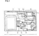
- FIG. 1 shows the internal structure adopted in a camera body 100 of the digital camera with a built-in projector achieved in the first embodiment in a view taken from the front side.
- the camera body 100 appears to assume a substantially rectangular shape when viewed from the front.
- a battery chamber 10 and a camera unit 20 are disposed respectively on the left side and on the right side, with a projector module 30 disposed between the battery chamber 10 and the camera unit 20.
- a power source battery is loaded through, for instance, the bottom of the camera body 100 into the battery chamber 10.
- the camera unit 20 includes a bending photographic optical system, a lens barrier, an image capturing portion and the like.
- the photographic optical system includes, as built-in components, a plurality of lenses, a mirror which is a bending optical system, an optical image blur correction mechanism and the like.
- a light flux originating from a subject first enters an objective lens 21a which is exposed at the front side of the camera body 100, is bent downward by the mirror and is transmitted through the group of lenses before entering the image capturing portion.
- the lens barrier which is driven by a barrier drive portion 22a, may take a closed (protective) position to shield the front surface of the objective lens 21a or an open (retreated) position to expose the objective lens 21a.
- a control circuit (not shown) executes control so that the barrier drive portion 22a drives the lens barrier from the closed position to the open position in response to a status shift of a power switch into an ON state and that the barrier drive portion 22a drives the lens barrier to the closed position in response to a status shift of the power switch into an Off state.
- An image sensor, an optical filter and the like are disposed at the image capturing portion.
- the light flux having passed through the photographic optical system is received at the image sensor near the bottom of the camera body 100 and undergoes photoelectric conversion at the image sensor.
- Image data are generated through various types of processing executed on the output from the image sensor resulting from the photoelectric conversion.
- the image data are then recorded into a memory card (not shown).
- a light emitting portion 70 which radiates auxiliary light toward the subject, is disposed near the top of the camera body 100 on its front side.
- a large-capacity capacitor 71 which accumulates an electric charge to be used to enable light emission at the light emitting portion 70, is disposed.
- a tripod locking member 50 with a screw hole through which a tripod is to be locked formed therein and a tilt member 60 that projects out of the camera body 100 during projection to enable adjustment of the angle with which the camera body 100 is set are disposed at the bottom of the camera body 100 over its central area.
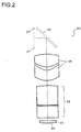
- FIG. 2 is a sectional view of the projector module taken through a section X in FIG. 1 .
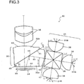
- FIG. 3 is a sectional view of the projector module taken from the camera front side.
- the projector module 30 includes a light source unit 31 that emits light in various colors, i.e., red light, green light and blue light, through time division, a total reflection prism 32, a protective member 33, a micro-mirror device 34, a projection lens 35, a mirror 36 and an aperture diaphragm 37.
- the light source unit 31 includes three high-luminance LEDs 31R, 31G and 31B which are turned on in time series, condenser lenses 38, each of which condenses light fluxes emitted from one of the high-luminance LEDs and outputs the condensed light fluxes as a substantially parallel light flux and a cross-dichroic prism 39 that directs the substantially parallel light flux toward the total reflection prism 32.
- the high-luminance LED 31R is a red-color LED that emits red light. While it is desirable to collimate the various light fluxes so as to achieve a completely parallel light flux, the term "substantially parallel light flux" is used above by taking into consideration possible manufacturing error.
- the high-luminance LED 31G is a green-color LED
- the high-lurninance LED 31B is a blue-color LED and they respectively emit green light and blue light.
- the light fluxes emitted from the individual high-luminance LEDs are condensed at the respective condenser lenses 38 each disposed frontward relative to one of the high-luminance LEDs and are output as substantially parallel light fluxes.
- the substantially parallel light fluxes thus output constitute a light flux that is radiated onto the micro-mirror device 34 as will be explained later.
- the distances between the three high-luminance LEDs 31R, 31G and 31B and the corresponding condenser lenses 3 8 are not uniform, with the high-luminance LED 31R and the corresponding condenser lens 38 set apart from each other by 0.48 mm, the high-luminance LED 31G and the corresponding condenser lens 38 set apart from each other by 0.37 mm and the high-luminance LED 31B and the corresponding condenser lens 38 set apart from each other by 0.25 mm, as shown in FIG. 3 .
- Such variance in the distance is assumed in order to ensure that no axial chromatic aberration occurs when light fluxes in the three different colors, i.e., red, blue and green, originating from the individual high-luminance LEDs are projected.
- the substantially parallel light fluxes in the three different colors departing the individual condenser lenses 38 are combined through time division at the cross-dichroic prism 39 and the resulting combined light flux is output from the cross-dichroic prism 39 toward the total reflection prism 32.
- the total reflection prism 32 is formed by pasting a first prism 32a and a second prism 32b together over a 0.02 mm gap. The presence of such a gap makes it possible to form a total reflection surface 41, which is to be described later.
- a surface 40 of the first prism 32a, located closer to the light source unit 31, via which the substantially parallel light fluxes (combined light flux) output from the light source unit 31 enters, is a free curved surface at which a light flux to enter a display area of the micro-mirror device 34 is formed by condensing the substantially parallel light fluxes and altering the sectional shape of the condensed substantially parallel light flux so as to substantially match the shape of the section of the light flux entering the display area with the shape formed by the outline of the display area at the micro-mirror device 34.
- the wording "substantially match” is used here by taking into consideration possible manufacturing error.
- the shape of the outline is normally rectangular, whereas the shape of the section of the substantially parallel light flux, i.e., the combined light flux output from the light source unit 31, is normally circular. Namely, at the free curved surface 40, the circular section of the combined light flux is altered to achieve a rectangular shape so substantially match the outline shape.
- the combined light flux output from the cross-dichroic prism 39 is totally reflected at the total reflection prism 32 and the reflected combined light flux is guided toward the display area of the micro-mirror device 34 to enter the display area.
- a surface 42 of the second prism 32b, located toward the projection lens 35, is an aspherical surface via which any aberration manifesting in the light reflected from the micro-mirror device 34 is corrected as the reflected light from the micro-mirror device 34 exits the surface 42 of the second prism 32b.
- the protective member 33 is a transparent member that protects the display surface of the micro-mirror device 34.
- the micro-mirror device 34 is a reflection-type display element that includes micro-mirrors arrayed in a two-dimensional pattern.
- the first prism 32a and the second prism 32b in the embodiment are each constituted of a resin (e.g., cyclo-olefin polymer) or a glass member with a refractive index of approximately 1.5309.
- the cross-dichroic prism 39 is constituted of a resin or a glass member with a refractive index of approximately 1.5187
- the protective member 33 is constituted of a resin or a glass member with a refractive index of approximately 1.52
- the condenser lenses 38 are constituted of a resin or a glass member with a refractive index of approximately 1.6231.
- the tilt angle of the reflecting surface of each of the mirrors constituting the micro-mirror device 34 can be adjusted to + 12° or -12°.
- an image corresponding to image data stored in a memory card can be projected on a surface outside the camera body 100.
- the control circuit in the camera body 100 transmits the projection target image data from the memory card to the micro-mirror device 34 and displays the image corresponding to the image data at the display surface of the micro-mirror device 34.
- the high-luminance LEDs 31R, 31G and 31B are sequentially turned on in this state, light fluxes emitted from each of the high-luminance LEDs are collimated via the corresponding condenser lens 38 and thus enter the cross-dichroic prism 39 as a substantially parallel light flux.
- the combined light flux achieved by combining the three substantially parallel light fluxes from the three condenser lenses 38 departs the cross-dichroic prism 39 toward the surface 40 of the first prism 32a.
- This combined light flux which is also a substantially parallel light flux, enters the total reflection prism 32 via the free curved surface 40, is totally reflected at the total reflection surface 41 and departs the total reflection prism 32 through a surface 44 before it enters the display surface (display area) of the micro-mirror device 34 via the protective member 33.
- the combined light flux having departed the cross-dichroic prism 39 is guided via the total reflection prism 32 toward the display area of the micro-mirror device 34 as the combined light flux is totally reflected at the total reflection surface 41 of the total reflection prism 32.
- the combined light flux guided to the display area of the micro-mirror device 34 enters the display area, light reflected from the display area enters the total reflection prism 32 through the surface 44 and the light having entered the total reflection prism 32 is transmitted through the total reflection surface 41 before exiting the total reflection prism 32 through the aspherical surface 42.
- the reflected optical image formed with the reflected light i.e., the projection target image displayed in the display area of the micro-mirror device 34, is projected onto a projection surface outside the camera.
- the total reflection surface 41 is the surface of the first prism 32a facing the 0.02 mm gap present between the first prism 32a and the second prism 32b as explained earlier.
- This projector module 30 is configured so that it can be installed in a portable electronic apparatus such as the camera body 100 shown in FIG. 1 .
- An exiting light axis 43 in FIG. 3 is the optical axis of the combined light flux output through the cross-dichroic prism 39.
- the light source unit 31 in the embodiment is disposed so that the exiting light axis 43 tilts at a predetermined angle along the direction indicated by an arrow 46 in FIG. 3 relative to the entry surface (surface 44) of the micro-mirror device 34. While it is desirable that the predetermined angle be approximately 10.59° as indicated in FIG. 3 , it may be any angle within the range of 10° through 11° in consideration of possible manufacturing error.
- a smaller apex angle 45 is formed by the exit surface (surface 44), through which the light flux having been totally reflected at the total reflection surface 41 exits, and the total reflection surface 41, compared to the apex angle formed by the same surfaces when the exiting light axis 43 extends parallel to the entry surface (surface 44) of the micro-mirror device 34.
- the distance between the surface 44 and the surface 42 can be reduced.
- the tilt of the exiting light axis 43 relative to the entry surface (surface 44) of the micro-mirror device 34 allows the total reflection prism 32 to assume a smaller size compared to that required when the exiting light axis 43 runs parallel to the entry surface (surface 44) of the micro-mirror device 34. While it is desirable that the apex angle be approximately 32°, as indicated in FIG. 3 , it may be any angle within the range of 31.5° through 32.5° in view of possible manufacturing error.
- the digital camera with a built-in projector achieved in the second embodiment of the present invention adopts a structure similar to that of the digital camera with a built-in projector achieved in the first embodiment
- the free curved surface in the second embodiment is formed at a position different from that of the free curved surface in the first embodiment.
- the following is a description of the digital camera with a built-in projector achieved in the second embodiment. It is to be noted that in the following description, components similar to those in the first embodiment are notated with the same reference numerals so as to preclude the necessity for a repeated explanation thereof.
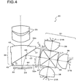
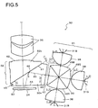
- FIG. 4 is a sectional view of the projector module achieved in the second embodiment, taken from the camera front side. It is distinguishable from the projector module in the first embodiment in that an exit surface 47 of the cross-dichroic prism 39 is a free curved surface and that the entry surface 40 of the first prism 32a facing opposite the exit surface 47 is not a free curved surface.
- exit surface 47 of the cross-dichroic prism 39 instead of the entry surface 40 of the first prism 32a, as a free curved surface where the combined light flux exiting the cross-dichroic prism 39 is condensed and the shape of the section of the combined light flux is altered so as to substantially match the shape of the section of the light flux to enter the display area of the micro-mirror device 34 with the shape of the outline of the display area.
- the present invention is not limited to the particulars of the embodiments described above and other embodiments that are conceivable within the technical scope of the present invention are also within the scope of invention.
Landscapes
- Engineering & Computer Science (AREA)
- Multimedia (AREA)
- Signal Processing (AREA)
- Projection Apparatus (AREA)
- Optical Elements Other Than Lenses (AREA)
Applications Claiming Priority (2)
| Application Number | Priority Date | Filing Date | Title |
|---|---|---|---|
| JP2011032292 | 2011-02-17 | ||
| JP2012001949A JP5310878B2 (ja) | 2011-02-17 | 2012-01-10 | 投射型表示装置、携帯型電子機器およびデジタルカメラ |
Publications (2)
| Publication Number | Publication Date |
|---|---|
| EP2490450A2 true EP2490450A2 (de) | 2012-08-22 |
| EP2490450A3 EP2490450A3 (de) | 2017-10-04 |
Family
ID=45592256
Family Applications (1)
| Application Number | Title | Priority Date | Filing Date |
|---|---|---|---|
| EP12155794.6A Withdrawn EP2490450A3 (de) | 2011-02-17 | 2012-02-16 | Projektionsanzeigevorrichtung, tragbare elektronische Vorrichtung und Digitalkamera |
Country Status (5)
| Country | Link |
|---|---|
| US (1) | US8827464B2 (de) |
| EP (1) | EP2490450A3 (de) |
| JP (1) | JP5310878B2 (de) |
| CN (1) | CN102645832B (de) |
| IN (1) | IN2012DE00422A (de) |
Families Citing this family (7)
| Publication number | Priority date | Publication date | Assignee | Title |
|---|---|---|---|---|
| JP2016025368A (ja) * | 2014-07-16 | 2016-02-08 | シャープ株式会社 | ヘッドホンユニット及びヘッドホン装置 |
| CN105182456A (zh) * | 2015-09-11 | 2015-12-23 | 成都迅达光电有限公司 | 棱镜和投影仪 |
| JP6642298B2 (ja) * | 2016-06-22 | 2020-02-05 | コニカミノルタ株式会社 | 投射型表示装置 |
| CN106873295B (zh) * | 2017-03-24 | 2019-08-02 | 广景视睿科技(深圳)有限公司 | 一种投影机 |
| JP6958530B2 (ja) * | 2018-10-10 | 2021-11-02 | セイコーエプソン株式会社 | 光学モジュールおよび頭部装着型表示装置 |
| JP7539053B2 (ja) * | 2019-10-25 | 2024-08-23 | パナソニックIpマネジメント株式会社 | 照明装置及び投写型映像表示装置 |
| US12591129B2 (en) | 2020-04-21 | 2026-03-31 | Designs For Vision, Inc. | Multiple light source configuration |
Citations (3)
| Publication number | Priority date | Publication date | Assignee | Title |
|---|---|---|---|---|
| JP2005062530A (ja) | 2003-08-14 | 2005-03-10 | Nec Viewtechnology Ltd | 投写型表示装置 |
| JP2011032292A (ja) | 2003-04-23 | 2011-02-17 | Medarex Inc | インターフェロンα受容体(IFNAR−1)に対するヒト化抗体 |
| JP2012001949A (ja) | 2010-06-16 | 2012-01-05 | Takiron Co Ltd | 雨水貯溜及び流出抑制のためのタンク |
Family Cites Families (21)
| Publication number | Priority date | Publication date | Assignee | Title |
|---|---|---|---|---|
| JP2000180967A (ja) | 1998-12-17 | 2000-06-30 | Dainippon Printing Co Ltd | プロジェクションスクリーンおよびプロジェクションディスプレイ装置 |
| JP3714003B2 (ja) | 1999-03-02 | 2005-11-09 | セイコーエプソン株式会社 | 投写型表示装置及びこれに用いられるプリズム |
| WO2000073844A1 (fr) * | 1999-05-28 | 2000-12-07 | Hitachi, Ltd. | Systeme optique a reflexion et projecteur reflectif contenant ce systeme |
| JP2002006225A (ja) * | 2000-06-23 | 2002-01-09 | Nikon Corp | 顕微鏡照明装置 |
| US6672721B2 (en) * | 2001-06-11 | 2004-01-06 | 3M Innovative Properties Company | Projection system having low astigmatism |
| JP2004070018A (ja) * | 2002-08-07 | 2004-03-04 | Mitsubishi Electric Corp | 投写装置の照明光学系構造及び投写装置 |
| AU2003288007A1 (en) * | 2002-11-07 | 2004-06-07 | Sony International (Europe) Gmbh | Illumination arrangement for a projection system |
| JP2004177801A (ja) * | 2002-11-28 | 2004-06-24 | Tamron Co Ltd | 電子デバイスプロジェクタ |
| JP4143444B2 (ja) * | 2003-03-07 | 2008-09-03 | キヤノン株式会社 | 照明光学系 |
| JP2004279498A (ja) * | 2003-03-13 | 2004-10-07 | Sharp Corp | 画像投影装置 |
| CN1570692A (zh) * | 2003-07-22 | 2005-01-26 | 吕兴增 | 投影显示装置 |
| US9201295B2 (en) * | 2005-01-25 | 2015-12-01 | Jabil Circuit, Inc. | High efficiency LED optical engine for a digital light processing (DLP) projector and method of forming same |
| US7529029B2 (en) * | 2005-07-29 | 2009-05-05 | 3M Innovative Properties Company | Polarizing beam splitter |
| US7362507B2 (en) | 2005-07-29 | 2008-04-22 | 3M Innovative Properties Company | Polarizing beam splitter |
| JP2007102095A (ja) * | 2005-10-07 | 2007-04-19 | Seiko Epson Corp | プロジェクタ及びデジタルカメラ |
| US7673993B2 (en) * | 2005-12-22 | 2010-03-09 | 3M Innovative Properties Company | Projection system using reflective polarizers |
| TWI311232B (en) * | 2006-10-05 | 2009-06-21 | Delta Electronics Inc | Light processing structure for a digital light processing projection device |
| JP5239237B2 (ja) * | 2007-07-19 | 2013-07-17 | コニカミノルタアドバンストレイヤー株式会社 | 画像投影装置 |
| CN101884001A (zh) * | 2007-11-30 | 2010-11-10 | 3M创新有限公司 | 包括复曲面的光学元件及其制备方法 |
| US8210689B2 (en) * | 2007-12-31 | 2012-07-03 | 3M Innovative Properties Company | Projection system |
| WO2009095406A1 (en) * | 2008-01-28 | 2009-08-06 | Upstream Engineering Oy | Double-reverse total-internal-reflection-prism optical engine |
-
2012
- 2012-01-10 JP JP2012001949A patent/JP5310878B2/ja active Active
- 2012-02-15 IN IN422DE2012 patent/IN2012DE00422A/en unknown
- 2012-02-16 EP EP12155794.6A patent/EP2490450A3/de not_active Withdrawn
- 2012-02-16 CN CN201210035515.6A patent/CN102645832B/zh active Active
- 2012-02-16 US US13/398,830 patent/US8827464B2/en active Active
Patent Citations (3)
| Publication number | Priority date | Publication date | Assignee | Title |
|---|---|---|---|---|
| JP2011032292A (ja) | 2003-04-23 | 2011-02-17 | Medarex Inc | インターフェロンα受容体(IFNAR−1)に対するヒト化抗体 |
| JP2005062530A (ja) | 2003-08-14 | 2005-03-10 | Nec Viewtechnology Ltd | 投写型表示装置 |
| JP2012001949A (ja) | 2010-06-16 | 2012-01-05 | Takiron Co Ltd | 雨水貯溜及び流出抑制のためのタンク |
Also Published As
| Publication number | Publication date |
|---|---|
| JP2012185479A (ja) | 2012-09-27 |
| CN102645832B (zh) | 2015-08-12 |
| US8827464B2 (en) | 2014-09-09 |
| IN2012DE00422A (de) | 2015-06-05 |
| CN102645832A (zh) | 2012-08-22 |
| JP5310878B2 (ja) | 2013-10-09 |
| US20120218522A1 (en) | 2012-08-30 |
| EP2490450A3 (de) | 2017-10-04 |
Similar Documents
| Publication | Publication Date | Title |
|---|---|---|
| US8827464B2 (en) | Projection display device, portable electronic apparatus and digital camera | |
| KR101321631B1 (ko) | 집광 광학계 및 투사형 화상 표시 장치 | |
| EP3447561B1 (de) | Head-up-anzeigevorrichtung | |
| KR100813983B1 (ko) | 조명 광학계, 조명 유니트 및 이를 채용한 화상 투영 장치 | |
| EP2350740B1 (de) | Projektionssystem | |
| US10656505B2 (en) | Optical projection device and projector | |
| US8746892B2 (en) | Illuminating optical system and projector device | |
| CN103852960B (zh) | 投影装置与聚光模组 | |
| CN108663816B (zh) | 光射出装置以及图像显示系统 | |
| CN101859052A (zh) | 投影机 | |
| WO2016098365A1 (ja) | 光学ユニット及びそれを備えたプロジェクター | |
| KR20200131219A (ko) | 화상 표시 장치 | |
| US11543648B2 (en) | Virtual image projection device | |
| US9703178B2 (en) | Projector having a rod integrator with an entrance plane smaller than an area light source | |
| US7159991B2 (en) | Projection type image display device | |
| JP4017167B2 (ja) | 投映表示装置 | |
| US8398244B2 (en) | Projector | |
| JP6673332B2 (ja) | プリズムユニットおよびプロジェクター | |
| JP5830218B2 (ja) | 画像表示装置 | |
| US20230205071A1 (en) | Projection lens and projection device | |
| US20250310495A1 (en) | Projector and projector system |
Legal Events
| Date | Code | Title | Description |
|---|---|---|---|
| PUAI | Public reference made under article 153(3) epc to a published international application that has entered the european phase |
Free format text: ORIGINAL CODE: 0009012 |
|
| AK | Designated contracting states |
Kind code of ref document: A2 Designated state(s): AL AT BE BG CH CY CZ DE DK EE ES FI FR GB GR HR HU IE IS IT LI LT LU LV MC MK MT NL NO PL PT RO RS SE SI SK SM TR |
|
| AX | Request for extension of the european patent |
Extension state: BA ME |
|
| RAP1 | Party data changed (applicant data changed or rights of an application transferred) |
Owner name: NIKON CORPORATION |
|
| PUAL | Search report despatched |
Free format text: ORIGINAL CODE: 0009013 |
|
| AK | Designated contracting states |
Kind code of ref document: A3 Designated state(s): AL AT BE BG CH CY CZ DE DK EE ES FI FR GB GR HR HU IE IS IT LI LT LU LV MC MK MT NL NO PL PT RO RS SE SI SK SM TR |
|
| AX | Request for extension of the european patent |
Extension state: BA ME |
|
| RIC1 | Information provided on ipc code assigned before grant |
Ipc: H04N 9/31 20060101AFI20170825BHEP |
|
| 17P | Request for examination filed |
Effective date: 20180404 |
|
| RBV | Designated contracting states (corrected) |
Designated state(s): AL AT BE BG CH CY CZ DE DK EE ES FI FR GB GR HR HU IE IS IT LI LT LU LV MC MK MT NL NO PL PT RO RS SE SI SK SM TR |
|
| GRAP | Despatch of communication of intention to grant a patent |
Free format text: ORIGINAL CODE: EPIDOSNIGR1 |
|
| INTG | Intention to grant announced |
Effective date: 20200310 |
|
| STAA | Information on the status of an ep patent application or granted ep patent |
Free format text: STATUS: THE APPLICATION IS DEEMED TO BE WITHDRAWN |
|
| 18D | Application deemed to be withdrawn |
Effective date: 20200721 |