EP2490748B1 - Embout malléable servant à l'application d'une substance sur un site cible au moyen d'un applicateur - Google Patents
Embout malléable servant à l'application d'une substance sur un site cible au moyen d'un applicateur Download PDFInfo
- Publication number
- EP2490748B1 EP2490748B1 EP20100757160 EP10757160A EP2490748B1 EP 2490748 B1 EP2490748 B1 EP 2490748B1 EP 20100757160 EP20100757160 EP 20100757160 EP 10757160 A EP10757160 A EP 10757160A EP 2490748 B1 EP2490748 B1 EP 2490748B1
- Authority
- EP
- European Patent Office
- Prior art keywords
- tip
- tube
- malleable member
- formable
- malleable
- Prior art date
- Legal status (The legal status is an assumption and is not a legal conclusion. Google has not performed a legal analysis and makes no representation as to the accuracy of the status listed.)
- Active
Links
Images




Classifications
-
- A—HUMAN NECESSITIES
- A61—MEDICAL OR VETERINARY SCIENCE; HYGIENE
- A61M—DEVICES FOR INTRODUCING MEDIA INTO, OR ONTO, THE BODY; DEVICES FOR TRANSDUCING BODY MEDIA OR FOR TAKING MEDIA FROM THE BODY; DEVICES FOR PRODUCING OR ENDING SLEEP OR STUPOR
- A61M25/00—Catheters; Hollow probes
- A61M25/0043—Catheters; Hollow probes characterised by structural features
- A61M25/005—Catheters; Hollow probes characterised by structural features with embedded materials for reinforcement, e.g. wires, coils, braids
-
- A—HUMAN NECESSITIES
- A61—MEDICAL OR VETERINARY SCIENCE; HYGIENE
- A61M—DEVICES FOR INTRODUCING MEDIA INTO, OR ONTO, THE BODY; DEVICES FOR TRANSDUCING BODY MEDIA OR FOR TAKING MEDIA FROM THE BODY; DEVICES FOR PRODUCING OR ENDING SLEEP OR STUPOR
- A61M35/00—Devices for applying media, e.g. remedies, on the human body
- A61M35/003—Portable hand-held applicators having means for dispensing or spreading integral media
-
- A—HUMAN NECESSITIES
- A61—MEDICAL OR VETERINARY SCIENCE; HYGIENE
- A61M—DEVICES FOR INTRODUCING MEDIA INTO, OR ONTO, THE BODY; DEVICES FOR TRANSDUCING BODY MEDIA OR FOR TAKING MEDIA FROM THE BODY; DEVICES FOR PRODUCING OR ENDING SLEEP OR STUPOR
- A61M2205/00—General characteristics of the apparatus
- A61M2205/02—General characteristics of the apparatus characterised by a particular materials
- A61M2205/0216—Materials providing elastic properties, e.g. for facilitating deformation and avoid breaking
-
- Y—GENERAL TAGGING OF NEW TECHNOLOGICAL DEVELOPMENTS; GENERAL TAGGING OF CROSS-SECTIONAL TECHNOLOGIES SPANNING OVER SEVERAL SECTIONS OF THE IPC; TECHNICAL SUBJECTS COVERED BY FORMER USPC CROSS-REFERENCE ART COLLECTIONS [XRACs] AND DIGESTS
- Y10—TECHNICAL SUBJECTS COVERED BY FORMER USPC
- Y10T—TECHNICAL SUBJECTS COVERED BY FORMER US CLASSIFICATION
- Y10T29/00—Metal working
- Y10T29/49—Method of mechanical manufacture
- Y10T29/49826—Assembling or joining
-
- Y—GENERAL TAGGING OF NEW TECHNOLOGICAL DEVELOPMENTS; GENERAL TAGGING OF CROSS-SECTIONAL TECHNOLOGIES SPANNING OVER SEVERAL SECTIONS OF THE IPC; TECHNICAL SUBJECTS COVERED BY FORMER USPC CROSS-REFERENCE ART COLLECTIONS [XRACs] AND DIGESTS
- Y10—TECHNICAL SUBJECTS COVERED BY FORMER USPC
- Y10T—TECHNICAL SUBJECTS COVERED BY FORMER US CLASSIFICATION
- Y10T83/00—Cutting
- Y10T83/04—Processes
- Y10T83/0596—Cutting wall of hollow work
Definitions
- the present disclosure generally relates to devices and systems for applying medical fluids to a target site. More particularly, the present disclosure relates to surgical or hemostatic applicators that include a malleable section, which can be bent and retained in a desired configuration.
- SURGIFLO® by Ferrosan TM is a pre-filled surgical hemostatic applicator that includes a pre-filled, flowable hemostat in a syringe that offers the option to customize the consistency by controlling the amount of saline or thrombin used.
- the flowable hemostat is a haemostatic Matrix, which is a sterile, absorbable porcine gelatin or other anti-bleeding agent.
- An applicator tip is secured to the syringe via a Luer-lock.
- the flowable haemostatic agent product is applied to a target area by positioning the free end of the applicator tip near a target site and then expelling an amount of the flowable haemostat.
- the surgical or haemostatic applicator is supplied with two applicator tips for precise placement of the flowable. This gives surgeons an option of choosing between a flexible and malleable applicator tip that has "memory" to ensure it stays at the optimum angle for easier access and exact product placement, and a non-malleable tip that can be cut with nursing dressing scissors to a desired length for providing the required penetration depth.
- the SURGIFLO® surgical or haemostatic applicator is particularly useful in connection with minimally invasive surgical techniques wherein a plurality of devices may be introduced into the body through small incisions.
- minimally invasive surgery involves laparoscopic surgical procedures. Laparoscopic procedures may be used to treat hernias, colon dysfunctions, gastroesophageal reflux disease, and gallbladder disorders. These procedures are considered minimally invasive, and typically a patient undergoing one of the procedures returns home hours after undergoing surgery. Generally, laparoscopic procedures require making at least one small incision in the patient's body near the area of interest. A cannula or trocar may be inserted into the incision for convenient instrument access.
- the known malleable tip retains the desired configuration until it is reshaped into a different configuration and it is shaped or formed, typically by manual bending, into a desired configuration.
- the known malleable/formable tip includes a tube with a large lumen configured to receive the flowable from the syringe.
- a malleable insert in the form of a steel wire is positioned within a second smaller lumen of the malleable tip. The malleable insert assists in retaining the formable tip in the desired configuration.
- the ability to shape the formable section increases the ability to accurately position the applicator device, while minimizing the user's manipulation of the device.
- WO 02/094334 discloses an elongated medical device insertable through an access pathway into a body vessel, organ or cavity to locate a therapeutic or diagnostic distal segment of the elongated medical device into alignment with an anatomic feature of interest having a malleable distal segment capable of being manually formed into a shape facilitating such alignment at room temperature.
- the elongated medical device includes a device body distal section formed of a malleable material including an elongated, malleable member disposed on or within the device body extending in the direction of the device body axis.;
- the malleable member is formed of a Beta III titanium alloy of the type exhibiting superelastic properties when subjected to strain at a bending strain of less than a set threshold strain and capable of undergoing plastic flow to take a set shape when subjected to a strain of greater than the set threshold at the same temperature.
- Beta III titanium is not a suitable material for being cut with a common pair of nursing dressing scissors since it is too hard and has a too high shear modulus. Further, this device is neither intended for nor suitable for being cut with a common pair of nursing dressing scissors.
- a tip that is malleable and can be cut to a desired length with a pair of nurses dressing scissors.
- Such a tip could be shaped and trimmed by a surgeon, nurse or other medical staff in situ so that the surgeon has a tip available with the desired shape and length as the actual situation on the operation table requires.
- an applicator device for applying a flowable agent to a target site as further disclosed in claim 1 is provided.
- the applicator device includes a tip with a proximate end for securing to an agent delivery apparatus and a free distal end.
- the tip is malleable or formable.
- the tip can be cut to length with a common pair of nursing dressing scissors. The ability to shape the tip to the desired configuration and the ability to trim the tip to the desired length increase the ability to accurately position the applicator device, while minimizing the user's manipulation of the device.
- an applicator device for applying an agent to a target site.
- the applicator device includes a formable tip configured for the passage of fluid therethrough, the formable tip having a proximal end portion and a distal end portion, the proximal end portion configured for communication with at least one fluid reservoir, the formable tip configured to be shaped into a desired configuration and the formable tip is configured to be cut to a desired length with a common pair of nurses dressing scissors.
- a tip as further disclosed in claim 1 for applying an agent to a target site includes a formable tube configured for the passage of fluid therethrough, said formable tube being configured to be able to be trimmed to length by cutting the formable tube with a pair of nursing dressing scissors or similar type of scissors.
- the method includes providing an applicator device with a formable tip, forming said tip to a desired configuration and cutting said formable tip to a desired length with a pair of nursing dressing scissors or similar type of scissors.
- system 1 generally illustrates one exemplary embodiment of a system for applying an agents, such as a haemostatic or a tissue sealant, to a target site within a body.
- the haemostat can be, for example, a bioresorbable gelatin matrix with or without thrombin.
- haemostat can be SURGIFLO® haemostatic Matrix manufactured by the assignee of the present disclosure.
- the applicator device is connected to a manually operated syringe material applicator 5.
- the syringe material applicator 5 is provided with a male Luer lock connector 7 and comprises a plunger 6 and a reservoir 8 containing the agent or medical fluid.
- the material applicator 5 supplies an agent or medical fluid to the applicator device. It should be understood that the embodiment of material applicator 5 is shown by way of example and not limitation. Additionally, the material applicator may employ alternative structures, such as multiple reservoirs.
- the applicator device includes a tip or delivery shaft 10.
- the tip 10 includes a tube 12 with a proximate end and a distal end 18.
- a Luer anchor 14 is secured to the proximate end.
- the distal end 18 is the free end of the tip 10.
- the tip 10 is inserted through a small surgical incision to position the free end 18 at or adjacent to a target site.
- the haemostatic can be transmitted from material applicator 5, through tube 12, and applied to the target site the free end 18.
- the free end of the tip 18 is provided with a conical distal portion. This conical portion 18 is not essential and the extremity of the tip 10 may just as well be formed by the tube 12 without the conical portion.
- the tube 12 can be formed or shaped into a desired shape or configuration by applying force, typically by hand, to bend the formable section. Tube 12 retains the configuration until force is again applied to the tube to form the tube into a different configuration.
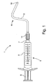
- formable tube 12 is bent at about somewhat less than ninety-degree angle and a somewhat more than ninety-degree angle. It should be understood that formable tube 12 could be bent at a variety of angles, including multiple angles, and shaped into a variety of custom configurations depending on the particular procedure or location of the target site. The bending and shape retention of formable tube 12 is discussed in more detail below.
- Fig. 2 shows the tip 10 in a straight configuration, and not connected to another device, i.e. the configuration it will typically have when it is packaged.
- the applicator tip 10 is part of a kit that comprises at least one material applicator 5, such as a syringe and one or more formable applicator tips 10 in a sterile package, such as a blister pack (not shown).
- the formable tip according to the present embodiment can be cut with a pair of standard dressing scissors by applying a force to the scissors that is within the comfortable range for an average operator like a nurse or surgeon, i.e. less than 80 Nm
- Tests with a pair of 17 cm long nursing dressing scissors on the formable tip 10 according to the present embodiment showed that the force that needs to be applied to the handles/finger holes 32 to cut the tube 12 was between 30 N and 60 N.
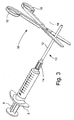
- Fig. 3 shows the applicator tip 10 connected via the Luer-lock to the material applicator 5 and in the same straight configuration as in Fig. 2 .
- a pair of nursing dressing scissors 30 has been brought in position for cutting the tip 10 to a desired length.
- the scissors 30 may be operated by a surgeon, a nurse or other medical staff on the operation floor.
- the tip 10 has been configured so that it can be cut with a common pair of nursing dressing scissors 30 by applying a force to the handles/fingerholes 32 that is within the comfort zone of an average operator of the scissors.
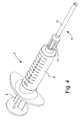
- Fig. 4 shows the applicator tip 10 of Fig. 3 after it has been cut to a desired length.
- Fig. 5 shows the applicator tip 10 of Fig. 4 after it has been bent into a desired shape.
- Fig. 6 shows the applicator tip 10 connected via the Luer-lock to the material applicator 5 and in the same double bent configuration as in Fig. 1 .
- a pair of nursing dressing scissors 30 has been brought in position for cutting the tip 10 to a desired length.
- the scissors 30 may be operated by a surgeon, a nurse or other medical staff on the operation floor.
- the tip 10 has been configured so that it can be cut with a common pair of nursing dressing scissors 30 by applying a force to the handles/fingerholes 32 that is within the comfort zone of an average operator of the scissors.
- the procedure according to the present disclosure involves preparing the applicator device before its actual deployment.
- a material applicator 5 is filled with a suitable agent (which could be a haemostatic matrix) with an applicator tip 10 connected to the material applicator 5.
- the surgeon or other medical staff shapes the tip 10 in a desired configuration and determines the desired length. If the desired length is less than the actual length the surgeon or other medical staff, uses a pair of nursing dressing scissors 30 to cut the tip 10 to a desired length. Alternatively, another regular pair of scissors similar to nursing dressing scissors may be used to cut the applicator tip 10.
- the cut is made at an angle of approximately ninety degrees to the (local) axial extend of the tube to avoid the creation of an angled and sharp free end of the tip 10. This concludes the preparation of the applicator device 1.
- the actual deployment of the applicator device 1 commences, for example by a surgeon placing the free end of the tip 10 in proximity of a target site and the agent is applied by manually pressing the plunger 6 of the material applicator 5.
- the tip 10 is still longer than desired it can be cut again in accordance with the procedure above.
- the applicator tip 10 is cut whilst it is not connected to the material applicator 5.
- the applicator tip 10 can be cut to desired length before it is attached to the material applicator 5. After the applicator tip 10 is cut, it is attached to the material applicator 5 and the agent is applied to the target area as described above.
- the tip 10 can be cut to length before bending it to shape or after bending it into shape.
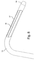
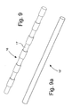
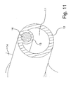
- Figs. 8 to 11 With reference to Figs. 8 to 11 the construction of the formable applicator tip 10 including the features allowing it to malleable or formable as well as being able to be cut with a pair of nursing dressing scissors 30 or similar scissors is explained in detail.
- the tube 12 is made of a suitable plastic or polymer material.
- the polymer or plastic material should have to a certain extend one or more of the following properties: easy to deform and stretch, stable enough to provide the tube with resistance to collapsing, elongation at breaking larger than 10%, low modulus of elasticity, good adhesive properties especially at low temperatures, low melt flow viscosity, kink resistance, stable material properties after sterilization with radiation.
- the tube material Polyolefin, polyethylene, polypropylene, polyether with rigid polyamide, PVC, acryl nitrile butadiene styrene (ABS), Polytetrafluoroethylene(PTFE). Mixtures of these materials are also suitable.
- the plastic material is relatively soft and preferably the hardness of the plastic material is in the range of 60 to 95, preferably approximately 85 Type A Shore Durometer.
- the plastic (polymer) material for the tube 12 is a medical grade polymer material.
- the plastic (polymer) material for the tube 12 is an extrusion grade and in yet another embodiment the plastic (polymer) material for the tube is a medical grade and extrusion grade polymer, preferably a thermoplastic polyolefin based polymer.
- the tube material should be suitable for being used in an injection molding or extrusion process.
- the tube 12 has a large lumen 11 for transport of the agent and a smaller lumen in which a malleable member 16 is received.
- the tube 12 has a circular cross-sectional outline.
- the tube 12 may have another cross-sectional outline, such as oval, hexagonal, pentagonal or other polygon shape.
- the malleable member 16 is made of a soft metal or other suitable material that is strong enough to maintain the desired configuration after bending, but at the same time soft and weak enough to be cut with regular nursing dressing scissors 30 or the like.
- Relatively pure aluminum approximately 99,00 to 99,99%
- aluminum alloys and other soft metals such as zinc, tin, gold, silver, titanium, copper, lead or alloys thereof and biocompatible plastics such as PEEK (polyether ether ketone) and HDPE (high density polyethylene are also examples of suitable materials.
- Suitable materials for the malleable member have: a hardness ranging from Brinell 10HB to 50HBn, a Young's modulus ranging from 50 GPa to 120 GPa and a shear modulus of 10 GPa to 50 GPa.
- the aluminium is medical grade aluminium or food grade aluminium.
- An example of a suitable aluminium grade is according to product specification 99.9% pure aluminium EN AW-1090
- the malleable member 16 extends the full length of the tube 12. The malleable member 16 does not extend into the distal end 18.
- the malleable member 16 is an aluminum wire with a circular cross-sectional shape and a diameter of approximately 1,3 mm.
- a suitable diameter for the malleable member 16, depending on the properties of the metal or alloy used for a tip with a single malleable member is approximately 0,8 to 2,0 mm.
- the cross-section of the malleable member 16 can have other shapes, such as oval, square, or other polygonal shape.
- the diameter of the tube 12 can vary between approximately 2,5 mm and approximately 7,0 mm, preferably approximately 4 mm.
- the wall thickness of the tube 12 is between 0,25 and 0,65 mm, preferably approximately 0,4 mm.
- the malleable member 16 is provided with a surface that improves adhesion with the plastic or polymer material of the tube 12.
- the wire of the malleable member 16 for the malleable member is an extruded aluminum wire and the outer surface of the wire is a smooth surface as obtained by an the extrusion process and thoroughly cleaned after the extrusion process to ensure that there are no residues of the lubrication oil used for the extrusion process on the outer surface.
- the surface of the wire of the malleable member 16 is provided with serrations or grooves 17 in the surface.
- the serrations 17 can be substantially circumferentially directed grooves around the wire 16, but can also have another direction or be other shape or pattern.
- the tube material is molded around the malleable member 16 and the tube material thereby fills the serrations and envelops the malleable member 16 and creates strong bonding and/or engagement of the malleable ember 16 and the tube material.
- the wire When the tube 12 is bend the wire may 16 tend to get displaced in a longitudinal direction relative to the tube material.
- Displacement between the malleable member 16 and the tube material could result in the wire material of the malleable member 16 protruding from the tube material after the tip 10 has been cut with the scissors 30.
- a protruding portion of wire is undesirable since the wire end could be sharp and cause damages to patient tissue.
- the adhesion between the tube material and the malleable member 16 ensures a smooth surface at the free end of the formable tip 10 after a cut with the scissors 30.
- the malleable member 16 and the tube 12 are produced in an extrusion process.
- the pre-produced wire for the malleable member 12 is fed to an extrusion machine with that has an extrusion mold and heated to approximately 180-230 Deg. Celsius at position where the wire is introduced into the extrusion process that forms the tube 12 with the wire integrated therein.
- the plastic material for the tube is also heated before and during the extrusion process to 80-120 Deg. Celsius.
- the elevated temperature of both the wire and the plastic material ensures a good adhesion between the wire and the plastic material, for wire with a smooth surface, for wire with a rough surface and for wire with serrations or grooves.
- the extruded tubing 12 with the embedded wire therein is cools down to ambient temperature there is a good bond between the outer surface of the wire and the tube material and the tube material adheres to the wire surface. This good bond prevents the tube from collapsing when the tube is bend and prevents that a portion of the malleable member material protrudes from the tubing material after the tube has been cut with a pair of scissors.
- the Luer anchor 14 is made from the same plastic or polymer material as the tube 12.
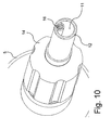
- Fig. 10 shows the free end of the tip 10 after being cut to length.
- Fig. 12 shows another embodiment of the malleable or formable tube 12 in a cross-sectional view.
- the tube 12 according to this embodiment can be used with the applicator device described above. In an elevated view the tube according to this embodiment looks like the tube 12 in Fig. 2 .
- the tube 12 is made of a plastic or polymer material with the same properties and materials as the tube according to the embodiment above.
- the tube 12 has a large lumen 11 for transport of the agent and five smaller lumens in each of which a malleable member 16 is received.
- the tube has a circular cross-sectional outline.
- the tube 12 may have another cross-sectional outline, such as oval, hexagonal, pentagonal or other polygon shape.
- the malleable members 16 are made of the same type of metal as the malleable member 16 in the embodiment above, i.e. a soft metal that is strong enough to maintain the desired configuration after bending, but at the same time soft and weak enough to be cut with regular nursing dressing scissors 30 or similar scissors.
- the malleable members 16 are aluminum wires with a circular cross-sectional shape and a diameter of 0,8 mm but may vary from approximately 0.4 mm to approximately 1.0 mm.
- the cross-section of the malleable members can have other shapes, such as oval, square or polygonal.
- the malleable members 16 are provided with a surface that improves adhesion with the plastic or polymer material of the tube 12.
- the surface is provided with grooves or serrations 17.
- the serrations 17 can be substantially circumferentially directed grooves on the wires 16, but can also be other shape of serrations.
- the tube material is molded around the wires and will envelop the wire and the serrations completely for optimal adhesion between the two materials.
- the wires 16 may tend to get displaced in a longitudinal direction relative to the tube material.
- Displacement between the malleable members 16 and the tube material could result in one or more of the wires 16 protruding from the tube material after the tip has been cut with the scissors 30.
- a protruding portion of wire is undesirable since the wire end could be sharp and cause damages to patient tissue.
- the adhesion between the tube material and the malleable members 16 ensures a smooth surface at the free end of the formable tip 10 after a cut with the scissors 30.
- the malleable member or members in the formable tube 12 can be arranged in other configurations than parallel with the longitudinal extension of the tube 12.
- the malleable member or members could for example be arranged in spiral configurations or as a mesh.
- the mesh can consist of a plurality of parallel wires and annular rings.
- formable tip has been shown with a single lumen for fluid transport.
- a formable tip with a plurality of lumens for fluid transport, which formable tip can be cut to length with a normal pair of nursing dressing scissors is also part of this disclosure
- the malleable member has been descried as a solid member it is also possible to have a compound structure with different materials or identical materials such as a bundle of fine fibers or rods of any of the materials mentioned hereabove or combinations of these materials.
- the malleable member can be made form multiple rigid pieces contained inside an elastomeric construct. The bending moment applied to the malleable section will result in restacking of the rigid pieces to a new state that is at a particular angle. The elastomeric construct will contribute to the rigidity of the system.
- the nursing dressing scissors shown in this disclosure have a blunt tip on both blades. It is noted that nursing dressing scissors with sharp tips and with one sharp tip and one blunt tip may equally be used.
- the expression "can be cut with a pair of scissors" in this application is to indicate that the cut can be made without extreme effort of an operator and/or and without substantially damaging the scissors.
Landscapes
- Health & Medical Sciences (AREA)
- Life Sciences & Earth Sciences (AREA)
- General Health & Medical Sciences (AREA)
- Public Health (AREA)
- Heart & Thoracic Surgery (AREA)
- Hematology (AREA)
- Anesthesiology (AREA)
- Animal Behavior & Ethology (AREA)
- Engineering & Computer Science (AREA)
- Biomedical Technology (AREA)
- Veterinary Medicine (AREA)
- Biophysics (AREA)
- Pulmonology (AREA)
- Media Introduction/Drainage Providing Device (AREA)
- Infusion, Injection, And Reservoir Apparatuses (AREA)
- Surgical Instruments (AREA)
- Coating Apparatus (AREA)
Claims (14)
- Dispositif applicateur (5) pour appliquer un agent sur un site spécifique dans un corps, ledit dispositif applicateur (5) comprenant un embout formable (10) configuré pour le passage de fluide à travers lui, l'embout formable (10) ayant une partie d'extrémité proximale et une partie d'extrémité distale, la partie d'extrémité proximale étant configurée pour communiquer avec au moins un réservoir de fluide, l'embout formable (10) étant configuré pour être formé dans une configuration souhaitée en le courbant et ledit embout formable (10) comprenant un tube formable ou malléable (12) formé d'un matériau tubulaire, ledit tube (12) étant pourvu d'une lumière (11) pour le transport de l'agent et d'au moins une lumière dans laquelle un organe malléable (16) est reçu, caractérisé en ce que l'embout formable (10) est configuré de manière à pouvoir être coupé à une longueur souhaitée au moyen d'une paire commune de ciseaux à pansements pour soins (30), l'organe malléable (16) étant en effet formé d'un métal tendre qui est suffisamment solide pour maintenir la configuration souhaitée après sa courbure mais qui est en même temps suffisamment tendre et faible pour pouvoir être découpé avec des ciseaux à pansements pour soins (30) ou des ciseaux similaires et l'organe malléable (16) étant pourvu d'une surface qui améliore l'adhésion au matériau tubulaire afin d'empêcher le déplacement entre l'organe malléable (16) et le matériau tubulaire lorsque ladite pointe (10) est courbée.
- Dispositif applicateur (5) selon la revendication 1, dans lequel l'organe malléable (16) est fabriqué en aluminium presque pur.
- Dispositif applicateur selon la revendication 2, dans lequel l'organe malléable (16) est un fil d'aluminium s'étendant substantiellement dans la direction de l'extension longitudinale du tube (12).
- Dispositif applicateur selon la revendication 3, dans lequel la surface de l'organe malléable (16) est pourvue d'indentations et les indentations sont de préférence des rainures orientées substantiellement circonférentiellement.
- Dispositif applicateur selon l'une quelconque des revendications 1 à 4, dans lequel l'organe malléable (16) présente une forme circulaire en section transversale et un diamètre compris entre environ 0,8 et environ 2,0 mm dans le cas où il y a un seul organe malléable (16) et les organes malléables (16) présentent un diamètre compris entre environ 0,3 mm et 1,0 mm lorsque l'embout est pourvu de plus d'un organe malléable.
- Dispositif applicateur selon l'une quelconque des revendications 1 à 5, dans lequel l'embout formable (10) peut être découpé avec une paire de ciseaux à pansements pour soins (30) ou une paire de ciseaux similaires en appliquant une force aux poignées ou aux trous pour les doigts qui ne dépasse pas 80 Newton.
- Dispositif applicateur selon l'une quelconque des revendications 1 à 6, dans lequel le matériau tubulaire adhère à la surface de l'organe malléable (16).
- Embout (10) destiné à l'utilisation avec un dispositif applicateur (5) pour appliquer un agent sur un site spécifique dans un corps, ledit embout comprenant un tube formable (12) configuré pour le passage de fluide à travers lui, ledit tube formable (12) étant configuré de manière à être formé dans une configuration souhaitée par courbure et ledit tube formable (12) étant formé d'un matériau tubulaire, ledit tube formable (12) étant pourvu d'une lumière (11) pour le transport de l'agent et d'au moins une lumière dans laquelle un organe malléable (16) est reçu, caractérisé en ce que le tube formable (12) est configuré de manière à pouvoir être découpé à une longueur souhaitée avec une paire commune de ciseaux à pansements pour soins (30), l'organe malléable (16) étant en effet formé d'un métal tendre qui est suffisamment solide pour maintenir la configuration souhaitée après sa courbure mais qui est en même temps suffisamment tendre et faible pour pouvoir être découpé avec des ciseaux à pansements pour soins (30) ou des ciseaux similaires et l'organe malléable (16) étant pourvu d'une surface qui améliore l'adhésion au matériau tubulaire afin d'empêcher le déplacement entre l'organe malléable (16) et le matériau tubulaire lorsque ledit tube (12) est courbé.
- Embout selon la revendication 8, dans lequel l'organe malléable (16) est fabriqué en aluminium presque pur.
- Embout selon la revendication 8, dans lequel l'organe malléable (16) est un fil d'aluminium s'étendant substantiellement dans la direction de l'extension longitudinale du tube (12).
- Embout selon la revendication 8, dans lequel l'organe malléable est pourvu d'une surface qui améliore l'adhésion avec le matériau tubulaire:
- Embout selon la revendication 11, dans lequel la surface de l'organe malléable (16) est pourvue d'indentations (17) et les indentations (17) sont de préférence des rainures orientées substantiellement circonférentiellement.
- Embout selon la revendication 12, dans lequel le ou les organes malléables ont une forme en section transversale circulaire et un diamètre compris entre environ 0,3 mm et environ 2,0 mm.
- Embout selon l'une quelconque des revendications 8 à 13, dans lequel l'embout formable (10) peut être découpé avec une paire de ciseaux à pansements pour soins (30) ou une paire de ciseaux similaires en appliquant une force aux poignées ou aux trous pour les doigts qui ne dépasse pas 80 Newton.
Applications Claiming Priority (2)
| Application Number | Priority Date | Filing Date | Title |
|---|---|---|---|
| US12/581,458 US20110092918A1 (en) | 2009-10-19 | 2009-10-19 | Malleable tip for applying an agent to a target site |
| PCT/EP2010/005598 WO2011047753A1 (fr) | 2009-10-19 | 2010-09-13 | Embout malléable servant à l'application d'une substance sur un site cible au moyen d'un applicateur |
Publications (2)
| Publication Number | Publication Date |
|---|---|
| EP2490748A1 EP2490748A1 (fr) | 2012-08-29 |
| EP2490748B1 true EP2490748B1 (fr) | 2014-06-11 |
Family
ID=43759677
Family Applications (1)
| Application Number | Title | Priority Date | Filing Date |
|---|---|---|---|
| EP20100757160 Active EP2490748B1 (fr) | 2009-10-19 | 2010-09-13 | Embout malléable servant à l'application d'une substance sur un site cible au moyen d'un applicateur |
Country Status (7)
| Country | Link |
|---|---|
| US (3) | US20110092918A1 (fr) |
| EP (1) | EP2490748B1 (fr) |
| JP (1) | JP5654606B2 (fr) |
| CN (2) | CN105363119A (fr) |
| CA (1) | CA2775175C (fr) |
| RU (1) | RU2551614C2 (fr) |
| WO (1) | WO2011047753A1 (fr) |
Families Citing this family (47)
| Publication number | Priority date | Publication date | Assignee | Title |
|---|---|---|---|---|
| JP6241624B2 (ja) * | 2012-03-06 | 2017-12-06 | フェロサン メディカル デバイシーズ エイ/エス | 止血ペーストを収容する加圧容器 |
| CN104349797B (zh) | 2012-06-12 | 2017-10-27 | 弗罗桑医疗设备公司 | 干止血组合物 |
| US20140031788A1 (en) | 2012-07-24 | 2014-01-30 | An-Min Jason Sung | Rigid reinforcing exoskeletal sleeve for delivery of flowable biocompatible materials |
| JP6376562B2 (ja) * | 2012-12-25 | 2018-08-22 | 扶桑薬品工業株式会社 | 止血剤アプリケータ |
| EP3010419B1 (fr) | 2013-06-21 | 2020-05-20 | Ferrosan Medical Devices A/S | Composition sèche dilatée sous vide, et seringue pour la retenir |
| CA2922816C (fr) * | 2013-09-02 | 2023-08-29 | Taisei Kako Co., Ltd. | Seringue et ensemble de seringues |
| EP3079731B1 (fr) | 2013-12-11 | 2018-08-08 | Ferrosan Medical Devices A/S | Composition sèche comprenant un améliorateur d'extrusion |
| US11376152B2 (en) | 2014-03-19 | 2022-07-05 | Purewick Corporation | Apparatus and methods for receiving discharged urine |
| US10004886B2 (en) * | 2014-06-27 | 2018-06-26 | Oral Health Outreach, Llc | Dual applicator |
| JP6726852B2 (ja) | 2014-10-13 | 2020-07-22 | フェッローサン メディカル ディバイス エー/エス | 止血および創傷治癒に使用するための乾燥組成物 |
| RU2705905C2 (ru) | 2014-12-24 | 2019-11-12 | Ферросан Медикал Дивайсиз А/С | Шприц для удерживания и смешивания первого и второго веществ |
| AU2016290433B2 (en) | 2015-07-03 | 2018-05-24 | Ferrosan Medical Devices A/S | Syringe for mixing two components and for retaining a vacuum in a storage condition |
| MY199064A (en) * | 2016-11-28 | 2023-10-11 | Inova Medical Pty Ltd | Percutaneous drainage device |
| WO2018144463A1 (fr) | 2017-01-31 | 2018-08-09 | Purewick Corporation | Appareil et procédés pour la réception d'urine excrétée |
| CN106979881A (zh) * | 2017-05-18 | 2017-07-25 | 桂林医学院 | 一种用于细胞块制备的离心管 |
| KR102492111B1 (ko) | 2018-05-01 | 2023-01-27 | 퓨어윅 코포레이션 | 유체 수집 장치 및 이를 사용하는 방법 |
| CN112367949B (zh) | 2018-05-01 | 2023-09-12 | 普利维克公司 | 流体收集装置、相关系统及相关方法 |
| US11938053B2 (en) | 2018-05-01 | 2024-03-26 | Purewick Corporation | Fluid collection devices, systems, and methods |
| WO2019212956A1 (fr) | 2018-05-02 | 2019-11-07 | Purewick Corporation | Dispositifs, systèmes et procédés de collecte de fluide |
| CN112368028A (zh) | 2018-05-09 | 2021-02-12 | 弗罗桑医疗设备公司 | 用于制备止血组合物的方法 |
| US11883618B2 (en) * | 2018-10-05 | 2024-01-30 | Acclarent, Inc. | Dilation catheter tip removal instrument |
| EP3986344B1 (fr) | 2019-06-21 | 2023-08-09 | Purewick Corporation | Dispositifs de collecte de fluide comprenant une zone de fixation de base, et systèmes et procédés associés |
| CA3143476C (fr) | 2019-07-11 | 2024-03-26 | Purewick Corporation | Dispositifs, systemes et procedes de collecte de fluide |
| EP3999003B1 (fr) | 2019-07-19 | 2024-05-01 | Purewick Corporation | Dispositifs de collecte de fluide comprenant au moins un matériau à mémoire de forme |
| WO2021086868A1 (fr) | 2019-10-28 | 2021-05-06 | Purewick Corporation | Ensembles de collecte de fluide comprenant un orifice d'échantillon |
| CA3158722A1 (fr) | 2019-12-23 | 2021-07-01 | Peter Lund Hammershoj | Tube applicateur |
| WO2021138414A1 (fr) | 2020-01-03 | 2021-07-08 | Purewick Corporation | Dispositifs de collecte d'urine ayant une partie relativement large et une partie allongée et méthodes associées |
| EP4120971A1 (fr) | 2020-03-19 | 2023-01-25 | Purewick Corporation | Ensembles de collecte de fluide comprenant un ou plusieurs éléments d'amélioration du mouvement |
| EP4125746B1 (fr) | 2020-03-26 | 2024-05-15 | Purewick Corporation | Dispositif de capture d'urine multicouche et procédés associés |
| WO2021211801A1 (fr) | 2020-04-17 | 2021-10-21 | Purewick Corporation | Ensembles de collecte de fluide comprenant une barrière imperméable aux fluides comportant une cuvette et une base |
| WO2021211729A1 (fr) | 2020-04-17 | 2021-10-21 | Purewick Corporation | Dispositifs de collecte de fluide, systèmes, et procédés de fixation solide d'une partie en saillie en position permettant l'utilisation |
| WO2021211599A1 (fr) | 2020-04-17 | 2021-10-21 | Purewick Corporation | Dispositifs cathéters féminins externes comprenant une coupelle urétrale et systèmes et procédés associés |
| US12491104B2 (en) | 2020-04-20 | 2025-12-09 | Purewick Corporation | Fluid collection devices adjustable between a vacuum-based orientation and a gravity-based orientation, and related systems and methods |
| EP4210643A1 (fr) | 2020-09-09 | 2023-07-19 | Purewick Corporation | Dispositifs, systèmes et procédés de collecte de fluide |
| US12569365B2 (en) * | 2020-10-21 | 2026-03-10 | Purewick Corporation | Fluid collection assemblies including at least one shape memory material disposed in the conduit |
| US12440370B2 (en) | 2020-10-21 | 2025-10-14 | Purewick Corporation | Apparatus with compressible casing for receiving discharged urine |
| US12070432B2 (en) | 2020-11-11 | 2024-08-27 | Purewick Corporation | Urine collection system including a flow meter and related methods |
| US12599495B2 (en) | 2021-01-05 | 2026-04-14 | Purewick Corporation | Male external catheter with attachment interface configured to bias against penis |
| EP4274522A1 (fr) | 2021-01-07 | 2023-11-15 | Purewick Corporation | Systèmes de collecte d'urine pouvant être fixés à un fauteuil roulant et méthodes associées |
| CA3195841A1 (fr) | 2021-02-26 | 2022-09-01 | Camille Rose Newton | Dispositifs de collecte de fluide comportant un puisard entre une ouverture de tube et une barriere, et systemes et procedes associes |
| US12551385B2 (en) | 2021-03-05 | 2026-02-17 | Purewick Corporation | Fluid collection assembly including a tube having porous wicking material for improved fluid transport |
| US12558472B2 (en) | 2021-03-05 | 2026-02-24 | Purewick Corporation | Portable fluid collection systems with storage and related methods |
| US12458525B2 (en) | 2021-03-10 | 2025-11-04 | Purewick Corporation | Acoustic silencer for a urine suction system |
| US12324767B2 (en) | 2021-05-24 | 2025-06-10 | Purewick Corporation | Fluid collection assembly including a customizable external support and related methods |
| US12575960B2 (en) | 2021-06-24 | 2026-03-17 | Purewick Corporation | Urine collection systems having one or more of volume, pressure, or flow indicators, and related methods |
| US12551366B2 (en) | 2021-08-02 | 2026-02-17 | Purewick Corporation | Fluid collection devices having multiple fluid collection regions, and related systems and methods |
| US12594062B2 (en) | 2021-09-08 | 2026-04-07 | Purewick Corporation | Fluid collection assemblies including an extension |
Family Cites Families (13)
| Publication number | Priority date | Publication date | Assignee | Title |
|---|---|---|---|---|
| US6025A (en) * | 1849-01-09 | Island | ||
| US3000A (en) * | 1843-03-10 | Improvement in sugar-boilers | ||
| US4578055A (en) * | 1979-07-25 | 1986-03-25 | Fischer Dan E | Controlled diffusion medicament applicator |
| US4617019A (en) * | 1984-09-28 | 1986-10-14 | Sherwood Medical Company | Catheter |
| US5540464A (en) * | 1994-10-04 | 1996-07-30 | J&W Scientific Incorporated | Capillary connector |
| US5810869A (en) * | 1996-11-18 | 1998-09-22 | Localmed, Inc. | Methods for loading coaxial catheters |
| FR2756493B1 (fr) * | 1996-12-02 | 2001-04-13 | Delab | Dispositif d'administration locale de formulations solides ou semi-solides |
| US6261014B1 (en) * | 1998-11-20 | 2001-07-17 | Sunglider, Inc. | Apparatus for applying a viscous lotion |
| US6562054B1 (en) * | 1998-12-02 | 2003-05-13 | Paul J. Weber | Liposuction cannulas with removable memory wire |
| US6733486B1 (en) * | 1999-12-22 | 2004-05-11 | Advanced Cardiovascular Systems, Inc. | Catheter having a reinforcing mandrel |
| DE60211896T2 (de) * | 2001-05-21 | 2007-05-10 | Medtronic, Inc., Minneapolis | Verformbare langgestreckte medizinische vorrichtung |
| US7635343B2 (en) * | 2005-04-21 | 2009-12-22 | Arteriocyte Medical Systems, Inc. | Fluid dispenser |
| CA2641699A1 (fr) * | 2007-10-30 | 2009-04-30 | Lifescan, Inc. | Methode permettant d'inserer un conduit flexible de dispositif medical dans un site cible d'un usager |
-
2009
- 2009-10-19 US US12/581,458 patent/US20110092918A1/en not_active Abandoned
-
2010
- 2010-09-13 US US13/502,578 patent/US8864723B2/en active Active
- 2010-09-13 CN CN201510523738.0A patent/CN105363119A/zh active Pending
- 2010-09-13 EP EP20100757160 patent/EP2490748B1/fr active Active
- 2010-09-13 RU RU2012113102/14A patent/RU2551614C2/ru active
- 2010-09-13 JP JP2012533498A patent/JP5654606B2/ja active Active
- 2010-09-13 CN CN2010800472163A patent/CN102711900A/zh active Pending
- 2010-09-13 WO PCT/EP2010/005598 patent/WO2011047753A1/fr not_active Ceased
- 2010-09-13 CA CA2775175A patent/CA2775175C/fr active Active
-
2014
- 2014-09-17 US US14/488,840 patent/US10960179B2/en active Active
Also Published As
| Publication number | Publication date |
|---|---|
| CN102711900A (zh) | 2012-10-03 |
| RU2551614C2 (ru) | 2015-05-27 |
| US20150073390A1 (en) | 2015-03-12 |
| CN105363119A (zh) | 2016-03-02 |
| US10960179B2 (en) | 2021-03-30 |
| CA2775175C (fr) | 2018-02-20 |
| CA2775175A1 (fr) | 2011-04-28 |
| US20110092918A1 (en) | 2011-04-21 |
| JP2013507994A (ja) | 2013-03-07 |
| EP2490748A1 (fr) | 2012-08-29 |
| JP5654606B2 (ja) | 2015-01-14 |
| WO2011047753A1 (fr) | 2011-04-28 |
| US20120209216A1 (en) | 2012-08-16 |
| RU2012113102A (ru) | 2013-11-27 |
| US8864723B2 (en) | 2014-10-21 |
Similar Documents
| Publication | Publication Date | Title |
|---|---|---|
| CA2775175C (fr) | Embout malleable servant a l'application d'une substance sur un site cible au moyen d'un applicateur | |
| JP5626738B2 (ja) | 組織縫合装置、移送用装置及びシステム、キット及びそのための方法 | |
| JP7643673B2 (ja) | ハイブリッド経中隔拡張器 | |
| KR101773205B1 (ko) | 조직 봉합 장치, 이송 장치 및 시스템, 키트 및 이를 위한 방법 | |
| JP2022106867A (ja) | 血管内部位から閉塞性物質を除去する装置および方法 | |
| CN113350658B (zh) | 柔性增强的神经血管导管 | |
| EP2844332B1 (fr) | Système de création de cavité pouvant être dirigé et incurvé | |
| US8961541B2 (en) | Vascular closure devices, systems, and methods of use | |
| US20090143808A1 (en) | Guided Tissue Cutting Device, Method of Use and Kits Therefor | |
| US20110144661A1 (en) | Tissue closure devices, device and systems for delivery, kits and methods therefor | |
| US20140081318A1 (en) | Tissue closure devices, device and systems for delivery, kits and methods therefor | |
| US20090054905A1 (en) | Embolization coil delivery systems and methods | |
| KR20190015479A (ko) | 홈 형성된 푸시 부재 세그먼트를 갖는 가이드 연장 카테터 | |
| US20120059337A1 (en) | Catheter with asymmetric or collapsible-expandable cross-section | |
| CN101217916A (zh) | 穿刺和闭合装置以及方法 | |
| WO2016191539A1 (fr) | Dispositifs et procédés pour l'administration de matières dans le nez | |
| WO2014018311A1 (fr) | Manchon exosquelettique à renfort rigide pour l'administration de matériaux biocompatibles liquides | |
| US20080195130A1 (en) | Method and apparatus for catheter removal | |
| CN211156127U (zh) | 房间隔造口器 | |
| HK1170922B (en) | Tissue closure devices, device and systems for delivery, kits and methods therefor |
Legal Events
| Date | Code | Title | Description |
|---|---|---|---|
| PUAI | Public reference made under article 153(3) epc to a published international application that has entered the european phase |
Free format text: ORIGINAL CODE: 0009012 |
|
| 17P | Request for examination filed |
Effective date: 20120521 |
|
| AK | Designated contracting states |
Kind code of ref document: A1 Designated state(s): AL AT BE BG CH CY CZ DE DK EE ES FI FR GB GR HR HU IE IS IT LI LT LU LV MC MK MT NL NO PL PT RO SE SI SK SM TR |
|
| DAX | Request for extension of the european patent (deleted) | ||
| GRAP | Despatch of communication of intention to grant a patent |
Free format text: ORIGINAL CODE: EPIDOSNIGR1 |
|
| INTG | Intention to grant announced |
Effective date: 20140109 |
|
| GRAS | Grant fee paid |
Free format text: ORIGINAL CODE: EPIDOSNIGR3 |
|
| GRAA | (expected) grant |
Free format text: ORIGINAL CODE: 0009210 |
|
| AK | Designated contracting states |
Kind code of ref document: B1 Designated state(s): AL AT BE BG CH CY CZ DE DK EE ES FI FR GB GR HR HU IE IS IT LI LT LU LV MC MK MT NL NO PL PT RO SE SI SK SM TR |
|
| REG | Reference to a national code |
Ref country code: GB Ref legal event code: FG4D |
|
| REG | Reference to a national code |
Ref country code: CH Ref legal event code: EP |
|
| REG | Reference to a national code |
Ref country code: IE Ref legal event code: FG4D |
|
| REG | Reference to a national code |
Ref country code: DE Ref legal event code: R082 Ref document number: 602010016667 Country of ref document: DE Representative=s name: BOEHMERT & BOEHMERT, DE Ref country code: DE Ref legal event code: R082 Ref document number: 602010016667 Country of ref document: DE Representative=s name: BOEHMERT & BOEHMERT ANWALTSPARTNERSCHAFT MBB -, DE |
|
| REG | Reference to a national code |
Ref country code: AT Ref legal event code: REF Ref document number: 671929 Country of ref document: AT Kind code of ref document: T Effective date: 20140715 |
|
| REG | Reference to a national code |
Ref country code: DE Ref legal event code: R096 Ref document number: 602010016667 Country of ref document: DE Effective date: 20140724 |
|
| PG25 | Lapsed in a contracting state [announced via postgrant information from national office to epo] |
Ref country code: NO Free format text: LAPSE BECAUSE OF FAILURE TO SUBMIT A TRANSLATION OF THE DESCRIPTION OR TO PAY THE FEE WITHIN THE PRESCRIBED TIME-LIMIT Effective date: 20140911 Ref country code: GR Free format text: LAPSE BECAUSE OF FAILURE TO SUBMIT A TRANSLATION OF THE DESCRIPTION OR TO PAY THE FEE WITHIN THE PRESCRIBED TIME-LIMIT Effective date: 20140912 Ref country code: FI Free format text: LAPSE BECAUSE OF FAILURE TO SUBMIT A TRANSLATION OF THE DESCRIPTION OR TO PAY THE FEE WITHIN THE PRESCRIBED TIME-LIMIT Effective date: 20140611 Ref country code: LT Free format text: LAPSE BECAUSE OF FAILURE TO SUBMIT A TRANSLATION OF THE DESCRIPTION OR TO PAY THE FEE WITHIN THE PRESCRIBED TIME-LIMIT Effective date: 20140611 |
|
| REG | Reference to a national code |
Ref country code: NL Ref legal event code: VDEP Effective date: 20140611 |
|
| REG | Reference to a national code |
Ref country code: AT Ref legal event code: MK05 Ref document number: 671929 Country of ref document: AT Kind code of ref document: T Effective date: 20140611 |
|
| REG | Reference to a national code |
Ref country code: LT Ref legal event code: MG4D |
|
| PG25 | Lapsed in a contracting state [announced via postgrant information from national office to epo] |
Ref country code: SE Free format text: LAPSE BECAUSE OF FAILURE TO SUBMIT A TRANSLATION OF THE DESCRIPTION OR TO PAY THE FEE WITHIN THE PRESCRIBED TIME-LIMIT Effective date: 20140611 Ref country code: LV Free format text: LAPSE BECAUSE OF FAILURE TO SUBMIT A TRANSLATION OF THE DESCRIPTION OR TO PAY THE FEE WITHIN THE PRESCRIBED TIME-LIMIT Effective date: 20140611 Ref country code: HR Free format text: LAPSE BECAUSE OF FAILURE TO SUBMIT A TRANSLATION OF THE DESCRIPTION OR TO PAY THE FEE WITHIN THE PRESCRIBED TIME-LIMIT Effective date: 20140611 |
|
| PG25 | Lapsed in a contracting state [announced via postgrant information from national office to epo] |
Ref country code: RO Free format text: LAPSE BECAUSE OF FAILURE TO SUBMIT A TRANSLATION OF THE DESCRIPTION OR TO PAY THE FEE WITHIN THE PRESCRIBED TIME-LIMIT Effective date: 20140611 Ref country code: ES Free format text: LAPSE BECAUSE OF FAILURE TO SUBMIT A TRANSLATION OF THE DESCRIPTION OR TO PAY THE FEE WITHIN THE PRESCRIBED TIME-LIMIT Effective date: 20140611 Ref country code: SK Free format text: LAPSE BECAUSE OF FAILURE TO SUBMIT A TRANSLATION OF THE DESCRIPTION OR TO PAY THE FEE WITHIN THE PRESCRIBED TIME-LIMIT Effective date: 20140611 Ref country code: PT Free format text: LAPSE BECAUSE OF FAILURE TO SUBMIT A TRANSLATION OF THE DESCRIPTION OR TO PAY THE FEE WITHIN THE PRESCRIBED TIME-LIMIT Effective date: 20141013 Ref country code: EE Free format text: LAPSE BECAUSE OF FAILURE TO SUBMIT A TRANSLATION OF THE DESCRIPTION OR TO PAY THE FEE WITHIN THE PRESCRIBED TIME-LIMIT Effective date: 20140611 Ref country code: CZ Free format text: LAPSE BECAUSE OF FAILURE TO SUBMIT A TRANSLATION OF THE DESCRIPTION OR TO PAY THE FEE WITHIN THE PRESCRIBED TIME-LIMIT Effective date: 20140611 |
|
| PG25 | Lapsed in a contracting state [announced via postgrant information from national office to epo] |
Ref country code: PL Free format text: LAPSE BECAUSE OF FAILURE TO SUBMIT A TRANSLATION OF THE DESCRIPTION OR TO PAY THE FEE WITHIN THE PRESCRIBED TIME-LIMIT Effective date: 20140611 Ref country code: AT Free format text: LAPSE BECAUSE OF FAILURE TO SUBMIT A TRANSLATION OF THE DESCRIPTION OR TO PAY THE FEE WITHIN THE PRESCRIBED TIME-LIMIT Effective date: 20140611 Ref country code: NL Free format text: LAPSE BECAUSE OF FAILURE TO SUBMIT A TRANSLATION OF THE DESCRIPTION OR TO PAY THE FEE WITHIN THE PRESCRIBED TIME-LIMIT Effective date: 20140611 Ref country code: IS Free format text: LAPSE BECAUSE OF FAILURE TO SUBMIT A TRANSLATION OF THE DESCRIPTION OR TO PAY THE FEE WITHIN THE PRESCRIBED TIME-LIMIT Effective date: 20141011 |
|
| REG | Reference to a national code |
Ref country code: DE Ref legal event code: R097 Ref document number: 602010016667 Country of ref document: DE |
|
| PLBE | No opposition filed within time limit |
Free format text: ORIGINAL CODE: 0009261 |
|
| STAA | Information on the status of an ep patent application or granted ep patent |
Free format text: STATUS: NO OPPOSITION FILED WITHIN TIME LIMIT |
|
| PG25 | Lapsed in a contracting state [announced via postgrant information from national office to epo] |
Ref country code: MC Free format text: LAPSE BECAUSE OF FAILURE TO SUBMIT A TRANSLATION OF THE DESCRIPTION OR TO PAY THE FEE WITHIN THE PRESCRIBED TIME-LIMIT Effective date: 20140611 Ref country code: LU Free format text: LAPSE BECAUSE OF FAILURE TO SUBMIT A TRANSLATION OF THE DESCRIPTION OR TO PAY THE FEE WITHIN THE PRESCRIBED TIME-LIMIT Effective date: 20140913 Ref country code: DK Free format text: LAPSE BECAUSE OF FAILURE TO SUBMIT A TRANSLATION OF THE DESCRIPTION OR TO PAY THE FEE WITHIN THE PRESCRIBED TIME-LIMIT Effective date: 20140611 |
|
| REG | Reference to a national code |
Ref country code: CH Ref legal event code: PL |
|
| 26N | No opposition filed |
Effective date: 20150312 |
|
| REG | Reference to a national code |
Ref country code: IE Ref legal event code: MM4A |
|
| REG | Reference to a national code |
Ref country code: DE Ref legal event code: R097 Ref document number: 602010016667 Country of ref document: DE Effective date: 20150312 |
|
| PG25 | Lapsed in a contracting state [announced via postgrant information from national office to epo] |
Ref country code: LI Free format text: LAPSE BECAUSE OF NON-PAYMENT OF DUE FEES Effective date: 20140930 Ref country code: CH Free format text: LAPSE BECAUSE OF NON-PAYMENT OF DUE FEES Effective date: 20140930 Ref country code: SI Free format text: LAPSE BECAUSE OF FAILURE TO SUBMIT A TRANSLATION OF THE DESCRIPTION OR TO PAY THE FEE WITHIN THE PRESCRIBED TIME-LIMIT Effective date: 20140611 |
|
| PG25 | Lapsed in a contracting state [announced via postgrant information from national office to epo] |
Ref country code: IE Free format text: LAPSE BECAUSE OF NON-PAYMENT OF DUE FEES Effective date: 20140913 |
|
| PG25 | Lapsed in a contracting state [announced via postgrant information from national office to epo] |
Ref country code: SM Free format text: LAPSE BECAUSE OF FAILURE TO SUBMIT A TRANSLATION OF THE DESCRIPTION OR TO PAY THE FEE WITHIN THE PRESCRIBED TIME-LIMIT Effective date: 20140611 |
|
| PG25 | Lapsed in a contracting state [announced via postgrant information from national office to epo] |
Ref country code: MT Free format text: LAPSE BECAUSE OF FAILURE TO SUBMIT A TRANSLATION OF THE DESCRIPTION OR TO PAY THE FEE WITHIN THE PRESCRIBED TIME-LIMIT Effective date: 20140611 Ref country code: CY Free format text: LAPSE BECAUSE OF FAILURE TO SUBMIT A TRANSLATION OF THE DESCRIPTION OR TO PAY THE FEE WITHIN THE PRESCRIBED TIME-LIMIT Effective date: 20140611 Ref country code: BG Free format text: LAPSE BECAUSE OF FAILURE TO SUBMIT A TRANSLATION OF THE DESCRIPTION OR TO PAY THE FEE WITHIN THE PRESCRIBED TIME-LIMIT Effective date: 20140611 |
|
| PG25 | Lapsed in a contracting state [announced via postgrant information from national office to epo] |
Ref country code: TR Free format text: LAPSE BECAUSE OF FAILURE TO SUBMIT A TRANSLATION OF THE DESCRIPTION OR TO PAY THE FEE WITHIN THE PRESCRIBED TIME-LIMIT Effective date: 20140611 Ref country code: BE Free format text: LAPSE BECAUSE OF FAILURE TO SUBMIT A TRANSLATION OF THE DESCRIPTION OR TO PAY THE FEE WITHIN THE PRESCRIBED TIME-LIMIT Effective date: 20140611 Ref country code: HU Free format text: LAPSE BECAUSE OF FAILURE TO SUBMIT A TRANSLATION OF THE DESCRIPTION OR TO PAY THE FEE WITHIN THE PRESCRIBED TIME-LIMIT; INVALID AB INITIO Effective date: 20100913 |
|
| REG | Reference to a national code |
Ref country code: FR Ref legal event code: PLFP Year of fee payment: 7 |
|
| REG | Reference to a national code |
Ref country code: FR Ref legal event code: PLFP Year of fee payment: 8 |
|
| PG25 | Lapsed in a contracting state [announced via postgrant information from national office to epo] |
Ref country code: MK Free format text: LAPSE BECAUSE OF FAILURE TO SUBMIT A TRANSLATION OF THE DESCRIPTION OR TO PAY THE FEE WITHIN THE PRESCRIBED TIME-LIMIT Effective date: 20140611 |
|
| REG | Reference to a national code |
Ref country code: FR Ref legal event code: PLFP Year of fee payment: 9 |
|
| PG25 | Lapsed in a contracting state [announced via postgrant information from national office to epo] |
Ref country code: AL Free format text: LAPSE BECAUSE OF FAILURE TO SUBMIT A TRANSLATION OF THE DESCRIPTION OR TO PAY THE FEE WITHIN THE PRESCRIBED TIME-LIMIT Effective date: 20140611 |
|
| PGFP | Annual fee paid to national office [announced via postgrant information from national office to epo] |
Ref country code: DE Payment date: 20250822 Year of fee payment: 16 |
|
| PGFP | Annual fee paid to national office [announced via postgrant information from national office to epo] |
Ref country code: IT Payment date: 20250822 Year of fee payment: 16 |
|
| PGFP | Annual fee paid to national office [announced via postgrant information from national office to epo] |
Ref country code: GB Payment date: 20250910 Year of fee payment: 16 |
|
| PGFP | Annual fee paid to national office [announced via postgrant information from national office to epo] |
Ref country code: FR Payment date: 20250910 Year of fee payment: 16 |