EP2490765B1 - Gantry mit einem strahlenanalysator zur verwendung bei der teilchentherapie - Google Patents
Gantry mit einem strahlenanalysator zur verwendung bei der teilchentherapie Download PDFInfo
- Publication number
- EP2490765B1 EP2490765B1 EP10766060.7A EP10766060A EP2490765B1 EP 2490765 B1 EP2490765 B1 EP 2490765B1 EP 10766060 A EP10766060 A EP 10766060A EP 2490765 B1 EP2490765 B1 EP 2490765B1
- Authority
- EP
- European Patent Office
- Prior art keywords
- gantry
- momentum
- particle
- limiting
- emittance
- Prior art date
- Legal status (The legal status is an assumption and is not a legal conclusion. Google has not performed a legal analysis and makes no representation as to the accuracy of the status listed.)
- Revoked
Links
Images




Classifications
-
- A—HUMAN NECESSITIES
- A61—MEDICAL OR VETERINARY SCIENCE; HYGIENE
- A61N—ELECTROTHERAPY; MAGNETOTHERAPY; RADIATION THERAPY; ULTRASOUND THERAPY
- A61N5/00—Radiation therapy
- A61N5/10—X-ray therapy; Gamma-ray therapy; Particle-irradiation therapy
-
- A—HUMAN NECESSITIES
- A61—MEDICAL OR VETERINARY SCIENCE; HYGIENE
- A61N—ELECTROTHERAPY; MAGNETOTHERAPY; RADIATION THERAPY; ULTRASOUND THERAPY
- A61N5/00—Radiation therapy
- A61N5/01—Devices for producing movement of radiation source during therapy
-
- A—HUMAN NECESSITIES
- A61—MEDICAL OR VETERINARY SCIENCE; HYGIENE
- A61N—ELECTROTHERAPY; MAGNETOTHERAPY; RADIATION THERAPY; ULTRASOUND THERAPY
- A61N5/00—Radiation therapy
- A61N5/10—X-ray therapy; Gamma-ray therapy; Particle-irradiation therapy
- A61N5/103—Treatment planning systems
-
- A—HUMAN NECESSITIES
- A61—MEDICAL OR VETERINARY SCIENCE; HYGIENE
- A61N—ELECTROTHERAPY; MAGNETOTHERAPY; RADIATION THERAPY; ULTRASOUND THERAPY
- A61N5/00—Radiation therapy
- A61N5/10—X-ray therapy; Gamma-ray therapy; Particle-irradiation therapy
- A61N5/1077—Beam delivery systems
- A61N5/1081—Rotating beam systems with a specific mechanical construction, e.g. gantries
-
- G—PHYSICS
- G21—NUCLEAR PHYSICS; NUCLEAR ENGINEERING
- G21K—HANDLING OF PARTICLES OR IONISING RADIATION NOT OTHERWISE PROVIDED FOR; IRRADIATION DEVICES; GAMMA RAY OR X-RAY MICROSCOPES
- G21K1/00—Arrangements for handling particles or ionising radiation, e.g. focusing or moderating
- G21K1/02—Arrangements for handling particles or ionising radiation, e.g. focusing or moderating using diaphragms, collimators
-
- G—PHYSICS
- G21—NUCLEAR PHYSICS; NUCLEAR ENGINEERING
- G21K—HANDLING OF PARTICLES OR IONISING RADIATION NOT OTHERWISE PROVIDED FOR; IRRADIATION DEVICES; GAMMA RAY OR X-RAY MICROSCOPES
- G21K1/00—Arrangements for handling particles or ionising radiation, e.g. focusing or moderating
- G21K1/08—Deviation, concentration or focusing of the beam by electric or magnetic means
- G21K1/093—Deviation, concentration or focusing of the beam by electric or magnetic means by magnetic means
-
- G—PHYSICS
- G21—NUCLEAR PHYSICS; NUCLEAR ENGINEERING
- G21K—HANDLING OF PARTICLES OR IONISING RADIATION NOT OTHERWISE PROVIDED FOR; IRRADIATION DEVICES; GAMMA RAY OR X-RAY MICROSCOPES
- G21K5/00—Irradiation devices
- G21K5/04—Irradiation devices with beam-forming means
-
- A—HUMAN NECESSITIES
- A61—MEDICAL OR VETERINARY SCIENCE; HYGIENE
- A61N—ELECTROTHERAPY; MAGNETOTHERAPY; RADIATION THERAPY; ULTRASOUND THERAPY
- A61N5/00—Radiation therapy
- A61N5/10—X-ray therapy; Gamma-ray therapy; Particle-irradiation therapy
- A61N2005/1085—X-ray therapy; Gamma-ray therapy; Particle-irradiation therapy characterised by the type of particles applied to the patient
- A61N2005/1087—Ions; Protons
Definitions
- the present invention relates to a charged particle therapy apparatus used for radiation therapy. More particularly, this invention relates to a rotatable gantry designed for receiving a charged particle beam in a direction substantially along a rotation axis of the gantry, for transporting and for delivering said beam to a target to be treated.
- Radiotherapy using charged particles has proven to be a precise and conformal radiation therapy technique where a high dose to a target volume can be delivered while minimizing the dose to surrounding healthy tissues.
- a particle therapy apparatus comprises an accelerator producing energetic charged particles, a beam transport system for guiding the particle beam to one or more treatment rooms and, for each treatment room, a particle beam delivery system.
- Such a rotating beam delivery system is further named gantry.
- the target is generally positioned at a fixed position defined by the crossing of the rotation axis of the gantry and the central treatment beam axis. This crossing point is called isocenter and gantries of this type capable of delivering beams from various directions to the isocenter are called isocentric gantries.
- the gantry beam delivery system comprises devices for shaping the beam to match the target.
- An example of a dynamic radiation technique is the so-called pencil beam scanning (PBS) technique.
- PBS pencil beam scanning
- a narrow pencil beam is magnetically scanned across a plane orthogonal to the central beam axis.
- Lateral conformity in the target volume is obtained by adequate control of the scanning magnets.
- Depth conformity in the target volume is obtained by adequate control of the beam energy. In this way, a particle radiation dose can be delivered to the entire 3D target volume.
- the particle beam energies required to have sufficient penetration depth in the patient depend on the type of particles used. For example, for proton therapy, proton beam energies are typically ranging between 70 MeV and 250 MeV. For each required penetration depth the beam energy needs to be varied. The energy spread of the beam should be limited as this directly influences the so-called distal dose fall-off.
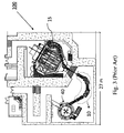
- an energy selection system is installed between the exit of the accelerator and the treatment room as shown in Figures 1 , 2 and 3 .
- ESS energy selection system
- Such an energy selection system is described by Jongen et al. in "The proton therapy system for the NPTC: equipment description and progress report", Nuc. Instr. Meth. In Phys. Res. B 113 (1996) 522-525 .
- the function of the Energy Selection System (ESS) is to transform the fixed energy beam extracted from the cyclotron (e.g.
- the resulting beam must have a verified and controlled absolute energy, energy spread and emittance.
- the first element of the ESS is a carbon energy degrader which allows to degrade the energy by putting carbon elements of a given thickness across the beam line.
- Such an energy degrader is described in patent EP1145605 .
- the degrader is followed by emittance slits to limit the beam emittance and by a momentum or energy analysing and selection device to restore (i.e. to limit) the energy spread in the beam.
- FIG. 1 A layout of such a known energy selection system 10 is shown in Fig. 1 together with a stationary, fixed energy accelerator 40 (in this example a cyclotron).
- a stationary, fixed energy accelerator 40 in this example a cyclotron.
- the beam passes through a 120° achromatic bend made up of two groups of two 30° bends.
- the momentum spread or the energy spread in the beam is limited by a slit placed at the center of the bend.
- the beam is focused by quadrupoles before the bend and between the two groups of two 30° bending magnets so that the emittance width of the beam is small and the dispersion is large at the position of the slit.
- the entire beam line starting at the energy degrader 41 up to the treatment isocenter 50 forms an optical system that is achromatic, i.e. a beam-optical system which has imaging properties independent from momentum (dispersionless) and independent from its transverse position.
- the beam line can be divided in multiple sections and each section is forming itself an achromat.
- the first section is the ESS 10 followed by an achromatic beamline section that brings the beam up to the entrance point of a treatment room.
- this entrance point is the entrance point or coupling point of the rotating gantry 15.
- the gantry beam line is then forming a third achromatic beam line section.
- the beam line comprises two achromatic beam line sections: a first section is the ESS 10 that brings the beam up to the gantry entrance point and the second achromatic section corresponds to the rotating gantry 15 beam line.
- the beam At the gantry entrance point, the beam must have the same emittance in X and Y in order to have a gantry beam optics solution that is independent from the gantry rotation angle.
- the X and Y axis are perpendicular to each other and to the central beam trajectory.
- the X axis is in the bending plane of the dipole magnets.
- the present invention aims to provide a solution to overcome at least partially the problems of the prior art. It is an objective of the present invention to provide a charged particle therapy apparatus that has a reduced size and that can be built at a reduced cost when compared to the prior art particle therapy apparatus.
- the functionalities of limiting the momentum spread (or energy spread, which is equivalent) and the emittance of the beam is performed by a separate device, namely with the energy selection system (ESS) 10, which is installed between the stationary accelerator 40 and the rotating gantry 15,.
- ESS energy selection system
- a first element of the ESS is an energy degrader 41 which is used to degrade the energy of the particle beam of the fixed-energy accelerator 40.
- a rotatable gantry beam delivery system having a gantry beam line configuration which fulfils multiple functions :
- the gantry also fulfils a second additional function of limiting the transverse beam emittance of the entering particle beam to a selected maximum value, which further reduces cost and size of the particle therapy facility.
- the gantry according to the invention also comprises a collimator installed in-between the gantry entrance point and a first quadrupole magnet in the gantry.
- This collimator is used for reducing the emittance of the beam before the beam is arriving at the first magnet in the gantry beam line.
- the above mentioned collimator is installed outside of the gantry, i.e. in-between the energy degrader and the entrance point of the gantry.
- a particle therapy apparatus comprising a stationary particle accelerator, an energy degrader and a rotatable gantry having means to limit the momentum spread of the beam.
- a gantry also comprises means to limit the emittance of the beam.
- a particle therapy apparatus comprising a stationary particle accelerator, an energy degrader, a rotatable gantry comprising means to limit the momentum spread of the beam and a collimator installed in-between said energy degrader and said gantry for limiting the emittance of the beam. More preferably, said gantry comprises additional means to limit the emittance of the beam.
- FIG. 4 A exemplary particle therapy configuration according to the invention is shown in Fig. 4 .
- the rotatable gantry according to the invention is coupled with a stationary-, fixed energy- particle accelerator 40 to form a single room particle therapy apparatus 100.
- An example of a particle accelerator for protons is a superconducting synchrocyclotron which has a compact geometry (e.g. with an extraction radius of 1,2 m).
- the gantry according to the invention is installed in the gantry room and a shielding wall (e.g. a 1,7 m thick concrete wall) separates the gantry room from the accelerator room.
- An energy degrader 41 is installed between the accelerator 40 and a gantry entrance point 45 (coupling point).
- This energy degrader 41 is positioned within the accelerator room just in front of the shielding wall 52 separating the accelerator room from the gantry room.
- the gantry entrance point 45 is located after the degrader 41 and is an entrance window for the beam line of the gantry.
- This entrance window 45 is the first part of a gantry beam line section where the beam is entering the gantry in a direction substantially along the rotation axis of the gantry.
- the rotation axis of the gantry is indicated by a horizontal dash-dotted line passing through the isocentrer 50 and the entrance point 45.
- there is no momentum or energy analyser device installed between the degrader and the gantry entrance point as is the case in the prior art systems ( Figures 1 to 3 ).
- the energy degrader 41 is for example a rapidly adjustable, servo controlled, rotating, variable thickness, cylinder of degrading material (as disclosed in EP1145605 ).
- the distance between the exit of the accelerator and the degrader can be about 2 m.
- Other types of energy degrading systems e.g. lateral moving wedge shaped based degraders can be used as well.
- the energy degrader currently used by the applicant has at its entrance an integrated horizontal-vertical beam profile monitor which allows measurement of the size and position of the beam spot and, through a control system algorithm, means for automatic tuning of the up-stream beam optics.
- the beam at the degrader 41 can be well defined, for example, the beam is focused into a small waist with a half width not exceeding 2 mm in both planes.
- the output emittance of the beam degraded in energy is dominated by multiple scattering in the degrader and is relatively independent from the input conditions.
- the resulting beam after energy degradation can be considered as a diverging beam from a virtual waist in X and Y at the degrader with a given size and divergence.
- the two orthogonal coordinate axis X and Y are perpendicular (transverse) to the central beam trajectory.
- the emittances in X and Y (also called “transverse emittances”) can be considered to be substantially identical at this point.
- the embodiment of the invention is a gantry configuration comprising means 43 to limit the momentum spread of the incoming beam.
- a beam entering the gantry comprising particles having an average momentum value and a momentum spread.
- a pair of momentum analysing slits 43 are installed in the gantry.
- These momentum analysing slits 43 are located at a position along the beam path where the particles of the beam are dispersed according to their momentum.
- these slits are installed at a position where the nominal dispersion is larger than the nominal beam size.
- the nominal dispersion is defined as a transversal displacement of a particle whose momentum differs by 1% (one percent) of an average momentum P of all particles of the beam.
- the nominal beam size is defined as the one sigma beam size value in X of a mono-energetic particle beam having the average momentum P.
- the momentum limiting slits can for example be installed at a position where the nominal beam size in X is between 0,2 cm and 1 cm and the nominal dispersion in X is between 1 cm and 3 cm.
- the maximum momentum spread that is required (selected) can be obtained.
- the nominal dispersion is large in comparison with the beam size at a position in-between gantry quadrupole magnet number seven and the second dipole magnet 48 and hence this is a preferred position to install the momentum spread limiting slits.
- These slits can for example be installed just before the second dipole magnet 48. The exact position can vary depending on the detailed gantry configuration.
- a pair of slits as means for reducing the momentum spread of the beam
- other means can be used as well.
- apertures or collimators with various diameters which can be put in the beam line, preferably at the above discussed positions.
- a gantry for delivering scanning beams at the treatment isocenter 50 is presented and the beam line of this gantry comprises three dipole magnets 47,48,49 and seven quadrupole magnets 44.
- scanning magnets 46 are installed upstream of the last dipole magnet 49. Between the gantry entrance point 45 and the first dipole magnet and in between the first and second dipole magnet there are respectively, two and five quadrupole magnets.
- means 42 to limit the transverse beam emittance can be installed in the gantry 15.
- two pairs of slits (in X and Y) limiting the beam divergence can for example be installed in-between the second quadrupole magnet and the first dipole magnet 47.
- the transverse beam emittance which is proportional to the beam divergence, is limited.
- the first two quadrupoles installed in the gantry in-between the entrance point 45 and the first dipole magnet 47 serve to focus the divergent beam, originating from the degrader, before the beam reaches the divergence limiting slits.
- the beam emittance needs to be reduced will depend on what the maximum emittance the gantry can accept to efficiently transport the beam and it will also depend on what the beam requirements are at the treatment isocenter (such as for example the beam size required at the treatment isocenter). Acceptable beam emittances and beam sizes may depend on the technique used for shaping the beam (e.g. pencil beam scanning or passive scattering).
- the example given in Fig. 4 is for a scanning beam delivery system.
- the beam emittance can for example be limited to 7,5 Pi mm mrad in both X and Y.
- a beam profile monitor can be installed (not shown on Fig. 4 ).
- a pair of slits in X and Y as means for reducing the divergence of the beam
- other means can be used as well. For example one can use apertures or collimators with various diameters which can be put in the beam line.
- a collimator (not shown in Fig. 4 ) can furthermore be installed upstream of the first quadrupole magnet in the gantry 15 to cut off already a part of the beam.
- This collimator can be installed in the gantry 15 in-between the entrance point 45 and the first quadrupole magnet of the gantry.
- such a collimator can be installed outside the gantry, i.e.
- the means 42 for limiting the emittance can be omitted.
- neutrons When a particle beam hits divergence and/or momentum limiting slits, neutrons are produced. To limit the neutron radiation at the level of the treatment isocenter 50 where the patient is positioned, adequate shielding need to be provided. As neutrons are mainly emitted in the direction of the beam, one can install just after the first dipole magnet, across the axis of rotation of the gantry, a neutron shielding plug 51 to shield the neutrons produced on means to limit the emittance of the beam installed upstream of the first dipole magnet 47. As the neutrons are mainly emitted in the direction of the beam, neutrons produced at the momentum limiting slits 43 are not directing to the patient. Nevertheless, a local neutron shielding (not shown on Fig. 4 ) can be installed around the momentum limiting slits 43 in order to reduce overall neutron background radiation.
- Fig 4 Details of the mechanical construction of the gantry have been omitted on purpose.
- mechanical elements not shown on Fig. 4 are: two spherical roller bearings for rotating the gantry by at least 180° around the patient, a gantry drive and braking system, a drum structure for supporting a cable spool, a counterweight needed to get the gantry balanced in rotation, ...
- the gantry configuration shown in Fig. 4 is based on a beam optical study performed with the beam optics "TRANSPORT" code (PSI Graphic Transport Framework by U. Rohrer based on a CERN-SLAC-FERMILAB version by K.L. Brown et al.).
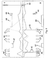
- the beam envelopes in X and Y in the gantry beam line for an entering proton beam of 170 MeV are shown in Fig. 5 as an example.
- the beam envelopes are plotted for the X direction and Y direction in the lower panel and upper panel, respectively.
- the emittance of the final beam is 12,5 Pi mm mrad. This corresponds to a situation where the divergence of the incoming beam has been limited to 6 mrad in X and Y.
- the beam transported through the system can then be considered as a beam starting at the degrader with a small beam spot of 1,25 mm and a divergence of 6 mrad.
- This beam optics a beam size at the treatment isocenter of 3,2 mm (one sigma value) is obtained which is an adequate value for performing pencil beam scanning.
- the positions of the quadrupole magnets and dipole magnets are shown on Fig. 5 .
- the transversal positions of the dipole magnets (the vertical gaps) are not shown on scale in this figure and the purpose is only to indicate their position along the central trajectory. Especially the gap in X an Y of the last bending magnet 49 are much larger than on the scale of Fig.
- the position of the scanning magnets along the beam path is indicated by a vertical line.
- the dotted line represents the nominal dispersion in X of the beam.
- a large nominal dispersion value is obtained and this is the position where the momentum limiting slits 43 are preferably installed.
- the position along the central beam trajectory of the momentum limiting slits 43 is indicated by a vertical line on Fig. 5 .
- the nominal beam size in X at the momentum limiting slits is about 0,23 cm while the nominal dispersion in X at this position is about 2,56 cm, hence obtaining a good momentum separation of the incoming beam.
- Preferably, also divergence limiting slits 42 are used. A good position for these slits 42 is indicated on Fig. 5 by a vertical line. At this position, the beam size in X and Y is about 1,8 cm and 0,6 cm, respectively.
- This beam optical solution presented fulfils the conditions of a double achromat.
- a three dipole gantry configuration was used with dipole bending angles of respectively 36°, 66° and 60°.
- the invention is not limited to a specific gantry configuration for what concerns number of dipoles or bending angles of the dipoles.
- the invention is neither limited to the number of quadrupole magnets and the relative positions of the quadrupoles with respect to the dipole magnets.
- the invention has been applied to a conical two dipole large throw gantry. This corresponds to the gantry configuration shown on Fig. 2 and Fig. 3 .
- These large throw gantries have been built by the applicant and are discussed by Pavlovic in " Beam-optics study of the gantry beam delivery system for light-ion cancer therapy", Nucl. Instr. Meth. In Phys. Res. A 399(1997) on page 440 .
- a first 45° dipole magnet bends the beam away from the axis of rotation of the gantry and the beam then further follows a second straight beam line section before entering the second 135° dipole magnet which is bending and directing the beam essentially perpendicular to the axis of rotation.
- the straight beam line section between the gantry entrance point and the first 45° dipole magnet comprises, in the original gantry design, four quadrupole magnets ( Fig 2 is a configuration having only two quadrupole magnets installed in this beam line section), and the second straight section between the first and second dipole magnet comprises five quadrupole magnets.
- the distance between the exit of the last bending magnet and the treatment isocenter is 3 m and the beam shaping elements configured in a so-called nozzle are installed upstream of the last bending magnet.
- This nozzle uses either the passive scattering technique or the scanning technique for shaping the beam conform the treatment target.
- the scanning magnets are part of the nozzle and are hence installed downstream of the last gantry dipole magnet.
- a beam optical analysis has been performed for this two dipole gantry configuration. The same conditions and requirements as discussed above have been respected.
- the resulting beam envelopes in this gantry are shown in Fig. 6 for a proton beam of 160 MeV.
- the beam envelopes are plotted for the X direction and Y direction in the lower panel and upper panel, respectively.
- the positions along the central beam path of the 45° dipole magnet 67, the 135° dipole magnet 68 and the various quadrupole magnets 44 are indicated in Fig. 6 .
- the energy degrader is installed just before the entrance window of the gantry and, as an example, in this calculation the divergence was cut at 8 mrad and the emittance of the final beam is 10 Pi mm mrad both in X and Y.
- the beam envelope as shown in Fig 6 starts at the gantry entrance window and the beam has a size of 1,25 mm (one sigma value).
- the first straight section between the entrance window and the first 45° gantry bending magnet 67 comprises four quadrupole magnets 44.
- Divergence limiting devices 42 are installed in between the second and third quadruople magnet and are indicated by a vertical line on Fig. 6 .
- the momentum spread limiting slits 43 are installed at a position where the nominal dispersion in X is large compared to the nominal beam size.
- the dotted line on Fig. 6 represents the nominal dispersion in X of the beam.
- the position of the momentum spread limiting slits 43 are indicated by a vertical line on Fig. 6 .
- the nominal dispersion is about 2,6 cm in X and the nominal beam size in X (one sigma value) is about 0,6 cm which is adequate for analysing the incoming beam according to momentum and limiting the momentum spread to a given value by setting the slits at the corresponding position.
- This gantry configuration used in this beam optics study also comprises two quadrupole magnets installed upstream of the 135° last dipole magnet 68 as indicated on Fig. 6 .
- This tuning solution a double waist in X and Y is obtained at isocenter having a beam size of 4 mm (one sigma value), which is suitable for performing pencil beam scanning.
- This beam optical solution fulfils the conditions of a double achromat.
- a particle therapy apparatus 100 can be formed by combining a stationary, fixed energy particle accelerator, an energy degrader and a rotatable gantry according to the invention, i.e. a rotatable gantry comprising means for limiting the energy spread or momentum spread of the beam and preferably also comprising means for limiting the emittance of the beam.
- a rotatable gantry comprising means for limiting the energy spread or momentum spread of the beam and preferably also comprising means for limiting the emittance of the beam.
- Fig. 4 which is an example of a proton therapy apparatus, a compact geometry can be obtained and the building footprint that is needed to install this apparatus is smaller than with a separate energy selection system.
- gantries for use with any type of charged particles such as e.g. a gantry for carbon ions or other light ions.
- Gantries for particle therapy have been designed since many years and, in combination with stationary, fixed energy particle accelerators, a separate energy selection system was always installed in the beam line between the accelerator and the gantry.
- a new gantry configuration is provided comprising means for limiting the energy spread or momentum spread of the beam and preferably also comprising means for limiting the emittance of the beam.
- the gantry itself comprises functionalities of the standard prior art energy selection system.
Landscapes
- Health & Medical Sciences (AREA)
- Engineering & Computer Science (AREA)
- Biomedical Technology (AREA)
- Physics & Mathematics (AREA)
- General Health & Medical Sciences (AREA)
- Pathology (AREA)
- Nuclear Medicine, Radiotherapy & Molecular Imaging (AREA)
- Radiology & Medical Imaging (AREA)
- Life Sciences & Earth Sciences (AREA)
- Animal Behavior & Ethology (AREA)
- Public Health (AREA)
- Veterinary Medicine (AREA)
- High Energy & Nuclear Physics (AREA)
- General Engineering & Computer Science (AREA)
- Spectroscopy & Molecular Physics (AREA)
- Radiation-Therapy Devices (AREA)
Claims (7)
- Drehbares Gantry (15) für den Empfang, den Transport und die Ausgabe eines Teilchenstrahls entlang einem Strahlweg zu einem Ziel zur Verwendung bei der Teilchentherapie, wobei das genannte Gantry (15) einen Eingangspunkt (45) für den Eintritt des Teilchenstrahls in einer Richtung, die im Wesentlichen entlang einer Rotationsachse des Gantrys ist, umfasst, dadurch gekennzeichnet, dass das Gantry (15) Mittel (43) zur Begrenzung einer Impulsverbreitung der Teilchen des Strahls zu einem ausgewählten maximalen Wert umfasst, wobei die genannten Mittel in einer Position entlang dem Strahlpfad lokalisiert sind, in dem eine nominale Dispersion gemäß einem Impuls eines Teilchens größer ist als eine nominale Strahlgröße in der genannten Position, wobei die genannte nominale Dispersion als eine transversale Verschiebung eines Teilchens definiert ist, dessen Impuls sich um 1 % (ein Prozent) von einem durchschnittlichen Impuls P aller Partikel des Strahls unterscheidet, wobei die genannte nominale Strahlgröße als ein Ein-Sigmastrahl-Größenwert eines mono-energetischen Teilchenstrahls mit dem durchschnittlichen Impuls definiert ist.
- Gantry (15) gemäß Anspruch 1, dadurch gekennzeichnet, dass das Gantry (15) weiterhin Mittel (42) zur Begrenzung einer transversalen Emission des Teilchenstrahls zu einem ausgewählten maximalen Wert umfasst.
- Gantry (15) gemäß Anspruch 2, dadurch gekennzeichnet, dass die Mittel (42) zur Begrenzung der transversalen Emission des Strahls den Mitteln (43) zur Begrenzung einer Impulsverbreitung der Teilchen des Strahls vorgeschaltet lokalisiert sind.
- Gantry (15) gemäß irgendeinem der Ansprüche 2 oder 3, dadurch gekennzeichnet, dass die Mittel (42) zur Begrenzung der transversalen Emission des Strahls Emissionsschlitze oder Emissionsöffnungen oder Emissionskollimatoren sind.
- Gantry (15) gemäß irgendeinem der voranstehenden Ansprüche, dadurch gekennzeichnet, dass die Mittel (43) zur Begrenzung einer Impulsverbreitung der Teilchen des Strahls Impulsanalyseschlitze oder Impulsanalyseöffnungen oder Impulsanalysekollimatoren sind.
- Teilchentherapiegerät (100), umfassend einen Teilchenstrahlgenerator (40), einen Energieabbauer (41) zur Reduzierung eines Impulses des genannten Teilchenstrahls und ein Gantry (15) gemäß irgendeinem der voranstehenden Ansprüche.
- Teilchentherapiegerät (100), umfassend einen Teilchenstrahlgenerator (40), einen Energieabbauer (41) zur Reduzierung eines Impulses des genannten Teilchenstrahls, einen Kollimator zur Begrenzung einer Emission des genannten Teilchenstrahls und ein Gantry (15) gemäß irgendeinem der voranstehenden Ansprüche, wobei der genannte Kollimator zwischen dem Energieabbauer (41) und dem Gantry (15) lokalisiert ist.
Priority Applications (1)
| Application Number | Priority Date | Filing Date | Title |
|---|---|---|---|
| EP10766060.7A EP2490765B1 (de) | 2009-10-23 | 2010-10-19 | Gantry mit einem strahlenanalysator zur verwendung bei der teilchentherapie |
Applications Claiming Priority (3)
| Application Number | Priority Date | Filing Date | Title |
|---|---|---|---|
| EP09173989 | 2009-10-23 | ||
| EP10766060.7A EP2490765B1 (de) | 2009-10-23 | 2010-10-19 | Gantry mit einem strahlenanalysator zur verwendung bei der teilchentherapie |
| PCT/EP2010/065707 WO2011048088A1 (en) | 2009-10-23 | 2010-10-19 | Gantry comprising beam analyser for use in particle therapy |
Publications (2)
| Publication Number | Publication Date |
|---|---|
| EP2490765A1 EP2490765A1 (de) | 2012-08-29 |
| EP2490765B1 true EP2490765B1 (de) | 2016-09-21 |
Family
ID=42035857
Family Applications (1)
| Application Number | Title | Priority Date | Filing Date |
|---|---|---|---|
| EP10766060.7A Revoked EP2490765B1 (de) | 2009-10-23 | 2010-10-19 | Gantry mit einem strahlenanalysator zur verwendung bei der teilchentherapie |
Country Status (8)
| Country | Link |
|---|---|
| US (3) | US9289624B2 (de) |
| EP (1) | EP2490765B1 (de) |
| JP (2) | JP5748153B2 (de) |
| KR (1) | KR101768028B1 (de) |
| CN (1) | CN102695544B (de) |
| BR (1) | BR112012009315B1 (de) |
| ES (1) | ES2605031T3 (de) |
| WO (1) | WO2011048088A1 (de) |
Families Citing this family (56)
| Publication number | Priority date | Publication date | Assignee | Title |
|---|---|---|---|---|
| KR101081839B1 (ko) | 2003-08-12 | 2011-11-09 | 로마 린다 유니버시티 메디칼 센터 | 모듈러 환자 서포트 시스템 |
| EP2490765B1 (de) | 2009-10-23 | 2016-09-21 | Ion Beam Applications | Gantry mit einem strahlenanalysator zur verwendung bei der teilchentherapie |
| EP2684034A4 (de) | 2011-03-07 | 2014-09-03 | Univ Loma Linda Med | Systeme, vorrichtungen und verfahren zur kalibrierung eines protonen-computertomographiescanners |
| WO2012147414A1 (ja) * | 2011-04-25 | 2012-11-01 | 住友重機械工業株式会社 | 荷電粒子線照射装置 |
| KR101403662B1 (ko) | 2011-12-29 | 2014-06-09 | 한국원자력연구원 | 양성자 가속기와 치료실이 서로 다른 층에 배치된 양성자 치료기 |
| CN104039391A (zh) * | 2012-02-03 | 2014-09-10 | 住友重机械工业株式会社 | 带电粒子束照射装置 |
| US9012866B2 (en) * | 2013-03-15 | 2015-04-21 | Varian Medical Systems, Inc. | Compact proton therapy system with energy selection onboard a rotatable gantry |
| US20140264065A1 (en) | 2013-03-15 | 2014-09-18 | Varian Medical Systems, Inc. | Energy degrader for radiation therapy system |
| US9630027B2 (en) * | 2013-07-11 | 2017-04-25 | Mitsubishi Electric Corporation | Beam transport system and particle beam therapy system |
| CN105993060B (zh) * | 2013-09-19 | 2018-03-30 | 普罗诺瓦解决方案有限责任公司 | 控制质子治疗系统的质子束的系统及方法 |
| ES2768659T3 (es) | 2013-09-27 | 2020-06-23 | Mevion Medical Systems Inc | Exploración de haces de partículas |
| US9962560B2 (en) | 2013-12-20 | 2018-05-08 | Mevion Medical Systems, Inc. | Collimator and energy degrader |
| US10675487B2 (en) | 2013-12-20 | 2020-06-09 | Mevion Medical Systems, Inc. | Energy degrader enabling high-speed energy switching |
| US9661736B2 (en) | 2014-02-20 | 2017-05-23 | Mevion Medical Systems, Inc. | Scanning system for a particle therapy system |
| JP6017486B2 (ja) * | 2014-03-20 | 2016-11-02 | 住友重機械工業株式会社 | 荷電粒子線治療装置、及び荷電粒子線の飛程調整方法 |
| CN105992449A (zh) * | 2015-02-26 | 2016-10-05 | 李晓粉 | 一种加速器束流引出装置 |
| DE102015106246A1 (de) * | 2015-04-23 | 2016-10-27 | Cryoelectra Gmbh | Strahlführungssystem, Teilchenstrahl-Therapieanlage und Verfahren |
| US10786689B2 (en) | 2015-11-10 | 2020-09-29 | Mevion Medical Systems, Inc. | Adaptive aperture |
| EP3167933A1 (de) * | 2015-11-16 | 2017-05-17 | Paul Scherrer Institut | Partikeltherapiegantry mit einem energieabbauer und einem achromatischen endbiegesystem |
| US10912953B2 (en) * | 2016-03-31 | 2021-02-09 | Varian Medical Systems Particle Therapy Gmbh | Adaptive pencil beam scanning |
| US9855445B2 (en) * | 2016-04-01 | 2018-01-02 | Varian Medical Systems, Inc. | Radiation therapy systems and methods for delivering doses to a target volume |
| US20180104510A1 (en) * | 2016-05-27 | 2018-04-19 | Faye Hendley Elgart | Orthogonal double dipole cancer therapy treatment beam scanning apparatus and method of use thereof |
| US20180028835A1 (en) * | 2016-05-27 | 2018-02-01 | James P. Bennett | Counter balanced / cantilevered charged particle cancer therapy gantry system and method of use thereof |
| US10118052B2 (en) * | 2016-05-27 | 2018-11-06 | Stephen L. Spotts | Charged particle cancer therapy installation system |
| WO2018009779A1 (en) | 2016-07-08 | 2018-01-11 | Mevion Medical Systems, Inc. | Treatment planning |
| CN107648746A (zh) * | 2016-07-25 | 2018-02-02 | 克洛依莱克特拉有限公司 | 束流引导系统、粒子束流治疗系统及其相关方法 |
| CN106139422B (zh) * | 2016-07-29 | 2018-11-30 | 中国原子能科学研究院 | 质子放射治疗回旋加速器的束流调制方法 |
| KR102590628B1 (ko) | 2016-09-09 | 2023-10-19 | 더 보드 오브 리젠츠 오브 더 유니버시티 오브 텍사스 시스템 | 방사선 전자 빔의 자기 제어를 위한 장치 및 방법 |
| EP3332755B1 (de) * | 2016-12-08 | 2019-07-03 | Ion Beam Applications | Partikeltherapievorrichtung zur augenbehandlung |
| US10974076B2 (en) | 2016-12-14 | 2021-04-13 | Varian Medical Systems, Inc | Dynamic three-dimensional beam modification for radiation therapy |
| US10485995B2 (en) * | 2016-12-28 | 2019-11-26 | Varian Medical Systems, Inc. | Compact lightweight high-performance proton therapy beamline |
| US11103730B2 (en) | 2017-02-23 | 2021-08-31 | Mevion Medical Systems, Inc. | Automated treatment in particle therapy |
| US10603518B2 (en) * | 2017-03-14 | 2020-03-31 | Varian Medical Systems, Inc. | Rotatable cantilever gantry in radiotherapy system |
| CN107018619B (zh) * | 2017-05-12 | 2018-05-11 | 合肥中科离子医学技术装备有限公司 | 一种紧凑型质子束流能量和能散度控制结构 |
| WO2019006253A1 (en) | 2017-06-30 | 2019-01-03 | Mevion Medical Systems, Inc. | CONFIGURABLE COLLIMATOR CONTROLLED BY LINEAR MOTORS |
| CN107596579B (zh) * | 2017-10-12 | 2018-06-05 | 合肥中科离子医学技术装备有限公司 | 基于紧凑型超导回旋加速器的质子治疗系统 |
| CN107846771A (zh) * | 2017-10-31 | 2018-03-27 | 华中科技大学 | 一种调节旋转机架等中心点束斑大小的方法及系统 |
| CN108449859B (zh) * | 2018-03-08 | 2019-12-06 | 西北核技术研究所 | 用于真空中的轮轴式粒子加速器降能装置及其降能方法 |
| CN108785874A (zh) * | 2018-04-18 | 2018-11-13 | 合肥中科离子医学技术装备有限公司 | 一种紧凑型单室质子治疗系统 |
| JP7118720B2 (ja) * | 2018-04-23 | 2022-08-16 | 株式会社東芝 | 粒子線治療システム |
| CN109224319B (zh) * | 2018-08-07 | 2020-06-23 | 中国原子能科学研究院 | 全超导质子治疗系统 |
| EP4082610B1 (de) | 2018-08-31 | 2023-09-20 | Neuboron Therapy System Ltd. | Therapiesystem mit neutronenerfassung |
| EP3934752A1 (de) | 2019-03-08 | 2022-01-12 | Mevion Medical Systems, Inc. | Abgabe von strahlung durch eine säule und erzeugung eines behandlungsplanes dafür |
| CN111714786B (zh) | 2019-03-18 | 2025-12-19 | 中硼(厦门)医疗器械有限公司 | 中子捕获治疗系统 |
| US10864384B2 (en) * | 2019-03-29 | 2020-12-15 | Varian Medical Systems Particle Therapy Gmbh | Non-achromatic compact gantry |
| US20200306562A1 (en) * | 2019-03-29 | 2020-10-01 | Varian Medical Systems Particle Therapy Gmbh | Compact rotational gantry for proton radiation systems |
| JP2022113920A (ja) * | 2019-06-06 | 2022-08-05 | 住友重機械工業株式会社 | 荷電粒子線照射設備 |
| CN111249633A (zh) * | 2020-03-21 | 2020-06-09 | 华中科技大学 | 用于质子治疗的大动量接受度超导旋转机架 |
| JP2021159110A (ja) | 2020-03-30 | 2021-10-11 | 住友重機械工業株式会社 | 荷電粒子線照射装置 |
| CN112121310A (zh) * | 2020-09-23 | 2020-12-25 | 中国科学院合肥物质科学研究院 | 一种用于超导加速器旋转机架二极铁的精密微调支撑装置 |
| US12245355B2 (en) | 2021-02-19 | 2025-03-04 | Mevion Medical Systems, Inc. | Gantry for a particle therapy system |
| JP7733450B2 (ja) * | 2021-02-25 | 2025-09-03 | 住友重機械工業株式会社 | 粒子線治療装置 |
| EP4359073A4 (de) * | 2021-06-21 | 2025-05-07 | Pronova Solutions, LLC | Energieauswahlsystem für kompakte protonentherapie |
| JP7668910B2 (ja) * | 2021-07-16 | 2025-04-25 | 中硼(厦▲門▼)医▲療▼器械有限公司 | 中性子捕捉療法システム |
| JP2023063024A (ja) * | 2021-10-22 | 2023-05-09 | 住友重機械工業株式会社 | 粒子線治療装置 |
| EP4245363A1 (de) * | 2022-03-18 | 2023-09-20 | Paul Scherrer Institut | Teilchenstrahltransportsystem zur abgabe von teilchenstrahltherapie |
Citations (10)
| Publication number | Priority date | Publication date | Assignee | Title |
|---|---|---|---|---|
| US5198674A (en) | 1991-11-27 | 1993-03-30 | The United States Of America As Represented By The United States Department Of Energy | Particle beam generator using a radioactive source |
| US20040113099A1 (en) | 2001-02-06 | 2004-06-17 | Hartmut Eickhoff | Gantry system for transport and delivery of a high energy ion beam in a heavy ion cancer therapy facility |
| WO2005102453A1 (en) | 2004-04-27 | 2005-11-03 | Paul Scherrer Institut | A system for the delivery of proton therapy |
| EP1166280B1 (de) | 1999-04-01 | 2005-11-09 | GSI Gesellschaft für Schwerionenforschung mbH | Abtastung mit einem ionenoptiksystem |
| US20060145088A1 (en) | 2003-06-02 | 2006-07-06 | Fox Chase Cancer Center | High energy polyenergetic ion selection systems, ion beam therapy systems, and ion beam treatment centers |
| US20080006776A1 (en) | 2004-12-13 | 2008-01-10 | National Institute Of Radiological Sciences | Charged Particle Beam Irradiator and Rotary Gantry |
| US20090032721A1 (en) | 2006-01-16 | 2009-02-05 | Mitsubishi Denki Kabushiki Kaisha | Particle-beam exposure apparatus and particle-beam therapeutic apparatus |
| US20090050819A1 (en) | 2004-12-22 | 2009-02-26 | Fox Chase Cancer Center | Laser-Accelerated Proton Therapy Units And Superconducting Electromagnet Systems For Same |
| WO2009040424A1 (en) | 2007-09-26 | 2009-04-02 | Ion Beam Applications S.A. | Particle beam transport apparatus and method of transporting a particle beam with small beam spot size |
| US20100213384A1 (en) | 2005-06-15 | 2010-08-26 | National Institute Of Radiological Sciences | Irradiation Field Forming Device |
Family Cites Families (33)
| Publication number | Priority date | Publication date | Assignee | Title |
|---|---|---|---|---|
| US3242796A (en) * | 1962-04-09 | 1966-03-29 | Beckman Instruments Inc | Slit control apparatus |
| US4870287A (en) * | 1988-03-03 | 1989-09-26 | Loma Linda University Medical Center | Multi-station proton beam therapy system |
| JP3472657B2 (ja) | 1996-01-18 | 2003-12-02 | 三菱電機株式会社 | 粒子線照射装置 |
| JPH11142596A (ja) * | 1997-08-28 | 1999-05-28 | Hitachi Ltd | 荷電粒子ビーム出射装置 |
| JPH11169470A (ja) * | 1997-12-12 | 1999-06-29 | Mitsubishi Electric Corp | 中性子発生装置 |
| EP0986071A3 (de) * | 1998-09-11 | 2000-03-29 | Gesellschaft für Schwerionenforschung mbH | Ionenstrahl-Therapieanlage und Verfahren zum betrieben der Anlage |
| BE1012358A5 (fr) | 1998-12-21 | 2000-10-03 | Ion Beam Applic Sa | Procede de variation de l'energie d'un faisceau de particules extraites d'un accelerateur et dispositif a cet effet. |
| US6810103B1 (en) * | 2001-07-16 | 2004-10-26 | Analogic Corporation | Gantry for combined tomography scanner |
| JP2003057397A (ja) | 2001-08-17 | 2003-02-26 | Mitsubishi Electric Corp | ビーム電流減衰器 |
| EP1421833A4 (de) | 2001-08-30 | 2006-04-05 | Tolemac Llc | Antiproton-produktion und freisetzung zur darstellung und termination unerwünschter zellen |
| DE602004017366D1 (de) * | 2003-05-13 | 2008-12-04 | Hitachi Ltd | Einrichtung zur Bestrahlung mit Teilchenstrahlen und Bestrahlungsplanungseinheit |
| DE10323654A1 (de) | 2003-05-26 | 2004-12-30 | GSI Gesellschaft für Schwerionenforschung mbH | Energiefiltereinrichtung |
| JP4114590B2 (ja) * | 2003-10-24 | 2008-07-09 | 株式会社日立製作所 | 粒子線治療装置 |
| JP2006280457A (ja) * | 2005-03-31 | 2006-10-19 | Hitachi Ltd | 荷電粒子ビーム出射装置及び荷電粒子ビーム出射方法 |
| DE102006012680B3 (de) * | 2006-03-20 | 2007-08-02 | Siemens Ag | Partikeltherapie-Anlage und Verfahren zum Ausgleichen einer axialen Abweichung in der Position eines Partikelstrahls einer Partikeltherapie-Anlage |
| JP4206414B2 (ja) * | 2006-07-07 | 2009-01-14 | 株式会社日立製作所 | 荷電粒子ビーム出射装置及び荷電粒子ビーム出射方法 |
| DE202006019307U1 (de) | 2006-12-21 | 2008-04-24 | Accel Instruments Gmbh | Bestrahlungsvorrichtung |
| JP4797140B2 (ja) * | 2007-01-18 | 2011-10-19 | 独立行政法人国立がん研究センター | 荷電粒子線照射装置 |
| DE102007032025A1 (de) * | 2007-07-10 | 2008-12-18 | Siemens Ag | Partikeltherapie-Anlage |
| DE102007033894B3 (de) * | 2007-07-20 | 2008-12-11 | Siemens Ag | Partikelstrahlapplikationsvorrichtung, Bestrahlungsvorrichtung sowie Verfahren zur Führung eines Partikelstrahls |
| JP4691576B2 (ja) * | 2008-05-20 | 2011-06-01 | 株式会社日立製作所 | 粒子線治療システム |
| US8178859B2 (en) | 2008-05-22 | 2012-05-15 | Vladimir Balakin | Proton beam positioning verification method and apparatus used in conjunction with a charged particle cancer therapy system |
| US7834336B2 (en) | 2008-05-28 | 2010-11-16 | Varian Medical Systems, Inc. | Treatment of patient tumors by charged particle therapy |
| JP5374731B2 (ja) * | 2008-11-26 | 2013-12-25 | 独立行政法人日本原子力研究開発機構 | レーザー駆動粒子線照射装置およびレーザー駆動粒子線照射装置の動作方法 |
| JP5225200B2 (ja) | 2009-05-27 | 2013-07-03 | 三菱電機株式会社 | 粒子線治療装置 |
| ATE512696T1 (de) | 2009-09-28 | 2011-07-15 | Ion Beam Applic | Kompaktes gantry zur partikeltherapie |
| EP2490765B1 (de) * | 2009-10-23 | 2016-09-21 | Ion Beam Applications | Gantry mit einem strahlenanalysator zur verwendung bei der teilchentherapie |
| WO2011053960A1 (en) | 2009-11-02 | 2011-05-05 | Procure Treatment Centers, Inc. | Compact isocentric gantry |
| DE102009053901B3 (de) | 2009-11-20 | 2011-04-28 | Abb Technology Ag | Ventilanordnung |
| EP2400506A1 (de) | 2010-06-23 | 2011-12-28 | GSI Helmholtzzentrum für Schwerionenforschung GmbH | Teilchenstrahlerzeugungsvorrichtung |
| JP5744578B2 (ja) | 2011-03-10 | 2015-07-08 | 住友重機械工業株式会社 | 荷電粒子線照射システム、及び中性子線照射システム |
| CN104039391A (zh) * | 2012-02-03 | 2014-09-10 | 住友重机械工业株式会社 | 带电粒子束照射装置 |
| US9012866B2 (en) | 2013-03-15 | 2015-04-21 | Varian Medical Systems, Inc. | Compact proton therapy system with energy selection onboard a rotatable gantry |
-
2010
- 2010-10-19 EP EP10766060.7A patent/EP2490765B1/de not_active Revoked
- 2010-10-19 JP JP2012534662A patent/JP5748153B2/ja active Active
- 2010-10-19 KR KR1020127011747A patent/KR101768028B1/ko active Active
- 2010-10-19 BR BR112012009315-0A patent/BR112012009315B1/pt active IP Right Grant
- 2010-10-19 CN CN201080047920.9A patent/CN102695544B/zh active Active
- 2010-10-19 WO PCT/EP2010/065707 patent/WO2011048088A1/en not_active Ceased
- 2010-10-19 ES ES10766060.7T patent/ES2605031T3/es active Active
-
2012
- 2012-04-19 US US13/502,946 patent/US9289624B2/en active Active
-
2015
- 2015-05-01 JP JP2015094190A patent/JP6105671B2/ja active Active
-
2016
- 2016-03-21 US US15/075,497 patent/US10052498B2/en active Active
-
2018
- 2018-07-23 US US16/042,928 patent/US10799714B2/en active Active
Patent Citations (10)
| Publication number | Priority date | Publication date | Assignee | Title |
|---|---|---|---|---|
| US5198674A (en) | 1991-11-27 | 1993-03-30 | The United States Of America As Represented By The United States Department Of Energy | Particle beam generator using a radioactive source |
| EP1166280B1 (de) | 1999-04-01 | 2005-11-09 | GSI Gesellschaft für Schwerionenforschung mbH | Abtastung mit einem ionenoptiksystem |
| US20040113099A1 (en) | 2001-02-06 | 2004-06-17 | Hartmut Eickhoff | Gantry system for transport and delivery of a high energy ion beam in a heavy ion cancer therapy facility |
| US20060145088A1 (en) | 2003-06-02 | 2006-07-06 | Fox Chase Cancer Center | High energy polyenergetic ion selection systems, ion beam therapy systems, and ion beam treatment centers |
| WO2005102453A1 (en) | 2004-04-27 | 2005-11-03 | Paul Scherrer Institut | A system for the delivery of proton therapy |
| US20080006776A1 (en) | 2004-12-13 | 2008-01-10 | National Institute Of Radiological Sciences | Charged Particle Beam Irradiator and Rotary Gantry |
| US20090050819A1 (en) | 2004-12-22 | 2009-02-26 | Fox Chase Cancer Center | Laser-Accelerated Proton Therapy Units And Superconducting Electromagnet Systems For Same |
| US20100213384A1 (en) | 2005-06-15 | 2010-08-26 | National Institute Of Radiological Sciences | Irradiation Field Forming Device |
| US20090032721A1 (en) | 2006-01-16 | 2009-02-05 | Mitsubishi Denki Kabushiki Kaisha | Particle-beam exposure apparatus and particle-beam therapeutic apparatus |
| WO2009040424A1 (en) | 2007-09-26 | 2009-04-02 | Ion Beam Applications S.A. | Particle beam transport apparatus and method of transporting a particle beam with small beam spot size |
Non-Patent Citations (3)
| Title |
|---|
| BLOSSER, H. ET AL.: "Medical Accelerator Projects at Michigan State University", PROCEEDINGS OF THE 1989 IEEE PARTICLE ACCELERATOR CONFERENCE, . 'ACCELERATOR SCIENCE AND TECHNOLOGY, 1989, pages 742 - 746, XP010081794 |
| SHERILL, B. ET AL.: "Use of multipole magnetic fields for making uniform irradiations", NUCLEAR INSTRUMENTS AND METHODS IN PHYSICS RESEARCH B40/41, 1989, North Holland, Amsterdam, pages 1004 - 1007, XP000046342 |
| YUKIO SATO: "A Design of the Radioactive Beam Line in the NIRS Medical Accelerator", JAPAN RADIOLOGICAL PHYSICS, vol. 7, no. 1, 1987, pages 21 - 35, XP055395902 |
Also Published As
| Publication number | Publication date |
|---|---|
| WO2011048088A1 (en) | 2011-04-28 |
| BR112012009315A2 (pt) | 2016-06-07 |
| EP2490765A1 (de) | 2012-08-29 |
| US10799714B2 (en) | 2020-10-13 |
| JP6105671B2 (ja) | 2017-03-29 |
| US20190151677A1 (en) | 2019-05-23 |
| KR101768028B1 (ko) | 2017-08-14 |
| US20120280150A1 (en) | 2012-11-08 |
| JP5748153B2 (ja) | 2015-07-15 |
| CN102695544B (zh) | 2016-05-11 |
| JP2013508046A (ja) | 2013-03-07 |
| JP2015163229A (ja) | 2015-09-10 |
| BR112012009315B1 (pt) | 2018-02-06 |
| US20160199671A1 (en) | 2016-07-14 |
| CN102695544A (zh) | 2012-09-26 |
| US9289624B2 (en) | 2016-03-22 |
| US10052498B2 (en) | 2018-08-21 |
| ES2605031T3 (es) | 2017-03-10 |
| KR20120107942A (ko) | 2012-10-04 |
Similar Documents
| Publication | Publication Date | Title |
|---|---|---|
| US10799714B2 (en) | Gantry comprising beam analyser for use in particle therapy | |
| US7816657B2 (en) | Particle therapy system | |
| US8748852B2 (en) | Compac gantry for particle therapy | |
| EP0986070B1 (de) | Ionenstrahl-Therapieanlage und Verfahren zum Betrieb der Anlage | |
| JP6499639B2 (ja) | 放射線治療システムのためのエネルギー分解器 | |
| US20170007848A1 (en) | Particle beam treatment system with solenoid magnets | |
| WO2020200848A1 (en) | Compact rotational gantry for proton radiation systems | |
| US20110098522A1 (en) | Particle Beam Treatment System | |
| EP3068489A1 (de) | Partikeltherapiesystem | |
| JP2012002772A (ja) | 深さ方向線量分布測定装置、粒子線治療装置及び粒子線照射装置 | |
| US20180277277A1 (en) | Degrader including boron carbide | |
| Klein et al. | PROTON THERAPY: ACCELERATOR ASPECTS AND PROCEDURES | |
| CN107648747A (zh) | 具有螺线管磁体的粒子束流治疗系统 |
Legal Events
| Date | Code | Title | Description |
|---|---|---|---|
| PUAI | Public reference made under article 153(3) epc to a published international application that has entered the european phase |
Free format text: ORIGINAL CODE: 0009012 |
|
| 17P | Request for examination filed |
Effective date: 20120523 |
|
| AK | Designated contracting states |
Kind code of ref document: A1 Designated state(s): AL AT BE BG CH CY CZ DE DK EE ES FI FR GB GR HR HU IE IS IT LI LT LU LV MC MK MT NL NO PL PT RO RS SE SI SK SM TR |
|
| DAX | Request for extension of the european patent (deleted) | ||
| 17Q | First examination report despatched |
Effective date: 20150826 |
|
| GRAP | Despatch of communication of intention to grant a patent |
Free format text: ORIGINAL CODE: EPIDOSNIGR1 |
|
| INTG | Intention to grant announced |
Effective date: 20160420 |
|
| RIN1 | Information on inventor provided before grant (corrected) |
Inventor name: JONGEN, YVES |
|
| GRAS | Grant fee paid |
Free format text: ORIGINAL CODE: EPIDOSNIGR3 |
|
| GRAA | (expected) grant |
Free format text: ORIGINAL CODE: 0009210 |
|
| AK | Designated contracting states |
Kind code of ref document: B1 Designated state(s): AL AT BE BG CH CY CZ DE DK EE ES FI FR GB GR HR HU IE IS IT LI LT LU LV MC MK MT NL NO PL PT RO RS SE SI SK SM TR |
|
| REG | Reference to a national code |
Ref country code: GB Ref legal event code: FG4D |
|
| REG | Reference to a national code |
Ref country code: CH Ref legal event code: EP |
|
| REG | Reference to a national code |
Ref country code: AT Ref legal event code: REF Ref document number: 830569 Country of ref document: AT Kind code of ref document: T Effective date: 20161015 |
|
| REG | Reference to a national code |
Ref country code: IE Ref legal event code: FG4D Ref country code: NL Ref legal event code: FP |
|
| REG | Reference to a national code |
Ref country code: FR Ref legal event code: PLFP Year of fee payment: 7 |
|
| REG | Reference to a national code |
Ref country code: DE Ref legal event code: R096 Ref document number: 602010036597 Country of ref document: DE |
|
| REG | Reference to a national code |
Ref country code: NO Ref legal event code: T2 Effective date: 20160921 |
|
| REG | Reference to a national code |
Ref country code: LT Ref legal event code: MG4D |
|
| PG25 | Lapsed in a contracting state [announced via postgrant information from national office to epo] |
Ref country code: RS Free format text: LAPSE BECAUSE OF FAILURE TO SUBMIT A TRANSLATION OF THE DESCRIPTION OR TO PAY THE FEE WITHIN THE PRESCRIBED TIME-LIMIT Effective date: 20160921 Ref country code: LT Free format text: LAPSE BECAUSE OF FAILURE TO SUBMIT A TRANSLATION OF THE DESCRIPTION OR TO PAY THE FEE WITHIN THE PRESCRIBED TIME-LIMIT Effective date: 20160921 |
|
| REG | Reference to a national code |
Ref country code: AT Ref legal event code: MK05 Ref document number: 830569 Country of ref document: AT Kind code of ref document: T Effective date: 20160921 |
|
| PG25 | Lapsed in a contracting state [announced via postgrant information from national office to epo] |
Ref country code: LV Free format text: LAPSE BECAUSE OF FAILURE TO SUBMIT A TRANSLATION OF THE DESCRIPTION OR TO PAY THE FEE WITHIN THE PRESCRIBED TIME-LIMIT Effective date: 20160921 Ref country code: GR Free format text: LAPSE BECAUSE OF FAILURE TO SUBMIT A TRANSLATION OF THE DESCRIPTION OR TO PAY THE FEE WITHIN THE PRESCRIBED TIME-LIMIT Effective date: 20161222 Ref country code: SE Free format text: LAPSE BECAUSE OF FAILURE TO SUBMIT A TRANSLATION OF THE DESCRIPTION OR TO PAY THE FEE WITHIN THE PRESCRIBED TIME-LIMIT Effective date: 20160921 |
|
| REG | Reference to a national code |
Ref country code: ES Ref legal event code: FG2A Ref document number: 2605031 Country of ref document: ES Kind code of ref document: T3 Effective date: 20170310 |
|
| PG25 | Lapsed in a contracting state [announced via postgrant information from national office to epo] |
Ref country code: EE Free format text: LAPSE BECAUSE OF FAILURE TO SUBMIT A TRANSLATION OF THE DESCRIPTION OR TO PAY THE FEE WITHIN THE PRESCRIBED TIME-LIMIT Effective date: 20160921 Ref country code: RO Free format text: LAPSE BECAUSE OF FAILURE TO SUBMIT A TRANSLATION OF THE DESCRIPTION OR TO PAY THE FEE WITHIN THE PRESCRIBED TIME-LIMIT Effective date: 20160921 |
|
| PG25 | Lapsed in a contracting state [announced via postgrant information from national office to epo] |
Ref country code: IS Free format text: LAPSE BECAUSE OF FAILURE TO SUBMIT A TRANSLATION OF THE DESCRIPTION OR TO PAY THE FEE WITHIN THE PRESCRIBED TIME-LIMIT Effective date: 20170121 Ref country code: CZ Free format text: LAPSE BECAUSE OF FAILURE TO SUBMIT A TRANSLATION OF THE DESCRIPTION OR TO PAY THE FEE WITHIN THE PRESCRIBED TIME-LIMIT Effective date: 20160921 Ref country code: PT Free format text: LAPSE BECAUSE OF FAILURE TO SUBMIT A TRANSLATION OF THE DESCRIPTION OR TO PAY THE FEE WITHIN THE PRESCRIBED TIME-LIMIT Effective date: 20170123 Ref country code: AT Free format text: LAPSE BECAUSE OF FAILURE TO SUBMIT A TRANSLATION OF THE DESCRIPTION OR TO PAY THE FEE WITHIN THE PRESCRIBED TIME-LIMIT Effective date: 20160921 Ref country code: BG Free format text: LAPSE BECAUSE OF FAILURE TO SUBMIT A TRANSLATION OF THE DESCRIPTION OR TO PAY THE FEE WITHIN THE PRESCRIBED TIME-LIMIT Effective date: 20161221 Ref country code: PL Free format text: LAPSE BECAUSE OF FAILURE TO SUBMIT A TRANSLATION OF THE DESCRIPTION OR TO PAY THE FEE WITHIN THE PRESCRIBED TIME-LIMIT Effective date: 20160921 Ref country code: SM Free format text: LAPSE BECAUSE OF FAILURE TO SUBMIT A TRANSLATION OF THE DESCRIPTION OR TO PAY THE FEE WITHIN THE PRESCRIBED TIME-LIMIT Effective date: 20160921 Ref country code: SK Free format text: LAPSE BECAUSE OF FAILURE TO SUBMIT A TRANSLATION OF THE DESCRIPTION OR TO PAY THE FEE WITHIN THE PRESCRIBED TIME-LIMIT Effective date: 20160921 |
|
| REG | Reference to a national code |
Ref country code: CH Ref legal event code: PL |
|
| REG | Reference to a national code |
Ref country code: DE Ref legal event code: R026 Ref document number: 602010036597 Country of ref document: DE |
|
| PLBI | Opposition filed |
Free format text: ORIGINAL CODE: 0009260 |
|
| 26 | Opposition filed |
Opponent name: VARIAN MEDICAL SYSTEMS, INC. Effective date: 20170619 |
|
| REG | Reference to a national code |
Ref country code: IE Ref legal event code: MM4A |
|
| PLAX | Notice of opposition and request to file observation + time limit sent |
Free format text: ORIGINAL CODE: EPIDOSNOBS2 |
|
| PG25 | Lapsed in a contracting state [announced via postgrant information from national office to epo] |
Ref country code: DK Free format text: LAPSE BECAUSE OF FAILURE TO SUBMIT A TRANSLATION OF THE DESCRIPTION OR TO PAY THE FEE WITHIN THE PRESCRIBED TIME-LIMIT Effective date: 20160921 Ref country code: LI Free format text: LAPSE BECAUSE OF NON-PAYMENT OF DUE FEES Effective date: 20161031 Ref country code: CH Free format text: LAPSE BECAUSE OF NON-PAYMENT OF DUE FEES Effective date: 20161031 |
|
| PG25 | Lapsed in a contracting state [announced via postgrant information from national office to epo] |
Ref country code: LU Free format text: LAPSE BECAUSE OF NON-PAYMENT OF DUE FEES Effective date: 20161019 |
|
| REG | Reference to a national code |
Ref country code: FR Ref legal event code: PLFP Year of fee payment: 8 |
|
| PG25 | Lapsed in a contracting state [announced via postgrant information from national office to epo] |
Ref country code: IE Free format text: LAPSE BECAUSE OF NON-PAYMENT OF DUE FEES Effective date: 20161019 Ref country code: SI Free format text: LAPSE BECAUSE OF FAILURE TO SUBMIT A TRANSLATION OF THE DESCRIPTION OR TO PAY THE FEE WITHIN THE PRESCRIBED TIME-LIMIT Effective date: 20160921 |
|
| PLBB | Reply of patent proprietor to notice(s) of opposition received |
Free format text: ORIGINAL CODE: EPIDOSNOBS3 |
|
| PGFP | Annual fee paid to national office [announced via postgrant information from national office to epo] |
Ref country code: NO Payment date: 20171027 Year of fee payment: 8 Ref country code: TR Payment date: 20171006 Year of fee payment: 8 Ref country code: FI Payment date: 20171027 Year of fee payment: 8 |
|
| PG25 | Lapsed in a contracting state [announced via postgrant information from national office to epo] |
Ref country code: CY Free format text: LAPSE BECAUSE OF FAILURE TO SUBMIT A TRANSLATION OF THE DESCRIPTION OR TO PAY THE FEE WITHIN THE PRESCRIBED TIME-LIMIT Effective date: 20160921 Ref country code: HU Free format text: LAPSE BECAUSE OF FAILURE TO SUBMIT A TRANSLATION OF THE DESCRIPTION OR TO PAY THE FEE WITHIN THE PRESCRIBED TIME-LIMIT; INVALID AB INITIO Effective date: 20101019 |
|
| PG25 | Lapsed in a contracting state [announced via postgrant information from national office to epo] |
Ref country code: MK Free format text: LAPSE BECAUSE OF FAILURE TO SUBMIT A TRANSLATION OF THE DESCRIPTION OR TO PAY THE FEE WITHIN THE PRESCRIBED TIME-LIMIT Effective date: 20160921 Ref country code: HR Free format text: LAPSE BECAUSE OF FAILURE TO SUBMIT A TRANSLATION OF THE DESCRIPTION OR TO PAY THE FEE WITHIN THE PRESCRIBED TIME-LIMIT Effective date: 20160921 Ref country code: MT Free format text: LAPSE BECAUSE OF NON-PAYMENT OF DUE FEES Effective date: 20161031 Ref country code: MC Free format text: LAPSE BECAUSE OF FAILURE TO SUBMIT A TRANSLATION OF THE DESCRIPTION OR TO PAY THE FEE WITHIN THE PRESCRIBED TIME-LIMIT Effective date: 20160921 |
|
| REG | Reference to a national code |
Ref country code: FR Ref legal event code: PLFP Year of fee payment: 9 |
|
| PG25 | Lapsed in a contracting state [announced via postgrant information from national office to epo] |
Ref country code: AL Free format text: LAPSE BECAUSE OF FAILURE TO SUBMIT A TRANSLATION OF THE DESCRIPTION OR TO PAY THE FEE WITHIN THE PRESCRIBED TIME-LIMIT Effective date: 20160921 |
|
| APBM | Appeal reference recorded |
Free format text: ORIGINAL CODE: EPIDOSNREFNO |
|
| APBP | Date of receipt of notice of appeal recorded |
Free format text: ORIGINAL CODE: EPIDOSNNOA2O |
|
| APAH | Appeal reference modified |
Free format text: ORIGINAL CODE: EPIDOSCREFNO |
|
| APBM | Appeal reference recorded |
Free format text: ORIGINAL CODE: EPIDOSNREFNO |
|
| APBP | Date of receipt of notice of appeal recorded |
Free format text: ORIGINAL CODE: EPIDOSNNOA2O |
|
| APBQ | Date of receipt of statement of grounds of appeal recorded |
Free format text: ORIGINAL CODE: EPIDOSNNOA3O |
|
| APBQ | Date of receipt of statement of grounds of appeal recorded |
Free format text: ORIGINAL CODE: EPIDOSNNOA3O |
|
| REG | Reference to a national code |
Ref country code: NO Ref legal event code: MMEP |
|
| PG25 | Lapsed in a contracting state [announced via postgrant information from national office to epo] |
Ref country code: NO Free format text: LAPSE BECAUSE OF NON-PAYMENT OF DUE FEES Effective date: 20181031 Ref country code: FI Free format text: LAPSE BECAUSE OF NON-PAYMENT OF DUE FEES Effective date: 20181019 |
|
| PG25 | Lapsed in a contracting state [announced via postgrant information from national office to epo] |
Ref country code: TR Free format text: LAPSE BECAUSE OF NON-PAYMENT OF DUE FEES Effective date: 20181019 |
|
| P01 | Opt-out of the competence of the unified patent court (upc) registered |
Effective date: 20230427 |
|
| PGFP | Annual fee paid to national office [announced via postgrant information from national office to epo] |
Ref country code: NL Payment date: 20231026 Year of fee payment: 14 |
|
| PGFP | Annual fee paid to national office [announced via postgrant information from national office to epo] |
Ref country code: GB Payment date: 20231027 Year of fee payment: 14 |
|
| PGFP | Annual fee paid to national office [announced via postgrant information from national office to epo] |
Ref country code: ES Payment date: 20231102 Year of fee payment: 14 |
|
| PGFP | Annual fee paid to national office [announced via postgrant information from national office to epo] |
Ref country code: IT Payment date: 20231023 Year of fee payment: 14 Ref country code: FR Payment date: 20231025 Year of fee payment: 14 Ref country code: DE Payment date: 20231027 Year of fee payment: 14 |
|
| PGFP | Annual fee paid to national office [announced via postgrant information from national office to epo] |
Ref country code: BE Payment date: 20231027 Year of fee payment: 14 |
|
| REG | Reference to a national code |
Ref country code: DE Ref legal event code: R103 Ref document number: 602010036597 Country of ref document: DE Ref country code: DE Ref legal event code: R064 Ref document number: 602010036597 Country of ref document: DE |
|
| APBU | Appeal procedure closed |
Free format text: ORIGINAL CODE: EPIDOSNNOA9O |
|
| RDAF | Communication despatched that patent is revoked |
Free format text: ORIGINAL CODE: EPIDOSNREV1 |
|
| RDAG | Patent revoked |
Free format text: ORIGINAL CODE: 0009271 |
|
| STAA | Information on the status of an ep patent application or granted ep patent |
Free format text: STATUS: PATENT REVOKED |
|
| 27W | Patent revoked |
Effective date: 20240515 |
|
| GBPR | Gb: patent revoked under art. 102 of the ep convention designating the uk as contracting state |
Effective date: 20240515 |