EP2491428B1 - Inversion de forme d'onde complète dans le domaine du temps de trajet - Google Patents
Inversion de forme d'onde complète dans le domaine du temps de trajet Download PDFInfo
- Publication number
- EP2491428B1 EP2491428B1 EP10825480.6A EP10825480A EP2491428B1 EP 2491428 B1 EP2491428 B1 EP 2491428B1 EP 10825480 A EP10825480 A EP 10825480A EP 2491428 B1 EP2491428 B1 EP 2491428B1
- Authority
- EP
- European Patent Office
- Prior art keywords
- earth model
- traveltime
- depth
- seismic data
- seismic
- Prior art date
- Legal status (The legal status is an assumption and is not a legal conclusion. Google has not performed a legal analysis and makes no representation as to the accuracy of the status listed.)
- Active
Links
Images

Classifications
-
- G—PHYSICS
- G01—MEASURING; TESTING
- G01V—GEOPHYSICS; GRAVITATIONAL MEASUREMENTS; DETECTING MASSES OR OBJECTS; TAGS
- G01V1/00—Seismology; Seismic or acoustic prospecting or detecting
- G01V1/28—Processing seismic data, e.g. for interpretation or for event detection
- G01V1/282—Application of seismic models, synthetic seismograms
-
- G—PHYSICS
- G01—MEASURING; TESTING
- G01V—GEOPHYSICS; GRAVITATIONAL MEASUREMENTS; DETECTING MASSES OR OBJECTS; TAGS
- G01V2210/00—Details of seismic processing or analysis
- G01V2210/60—Analysis
- G01V2210/67—Wave propagation modeling
- G01V2210/679—Reverse-time modeling or coalescence modelling, i.e. starting from receivers
Definitions
- Implementations of various technologies described herein generally relate to seismic data processing.
- Seismic exploration is widely used to locate and/or survey subterranean geological formations for hydrocarbon deposits. Since many commercially valuable hydrocarbon deposits are located beneath areas of land and bodies of water, various types of land and marine seismic surveys have been developed.
- seismic sensors are installed in specific locations around an area of the earth in which hydrocarbon deposits may exist.
- Seismic sources such as vibrators or air guns, may move across the area and produce acoustic signals, commonly referred to as "shots," directed down to the earth, where they are reflected from the various subterranean geological formations. Reflected signals are received by the sensors, digitized, and then transmitted to a survey database. The digitized signals are referred to as seismic data.
- the ultimate aim of this process is to build a representation of the subterranean geological formations beneath the surface of the earth. Analysis of the representation may indicate probable locations of hydrocarbon deposits in the subterranean geological formations.
- Full-waveform inversion is one approach in analyzing the seismic data.
- FWI is an approach to build a seismic velocity earth model that minimizes a misfit between seismic data received by sensors and predicted seismic data obtained from an earth model. Since the misfit is sensitive to both the amplitude and phase of the seismic data, FWI has the potential to deliver velocity earth models with higher resolution than conventional earth modeling techniques. Furthermore, given modern optimization techniques, FWI now has the potential to work with minimal user input. This has significant advantages over conventional velocity earth model building practices in complex areas such as salt provinces, which involve manually intensive workflows.
- Described herein are implementations of various technologies for performing a full-waveform inversion in the traveltime domain.
- a method for processing seismic data as defined by appended Claim 1.
- a computer system includes a memory with program instructions to cause a processor to predict seismic data according to an earth model in depth.
- a method for performing a full-waveform inversion in the traveltime domain begins with receiving an earth model in depth.
- the earth model in depth is expressed in terms of spatial (horizontal) coordinates and depth.
- the method includes receiving seismic data that has been acquired from seismic receivers.
- the seismic data may contain seismic responses to seismic sources that may have been obtained from the relatively same geographical area of the earth represented by the earth model in depth.
- the seismic data is typically presented in a data space domain defined by the location of the seismic receivers and either a time coordinate or a transform thereof, such as temporal frequency.
- seismic data is simulated according to the earth model in depth.
- the simulated seismic data represents the seismic data that may have been obtained from the geographical area of the earth represented in the earth model in depth.
- the simulated seismic data may be referred to as the predicted seismic data.
- the predicted seismic data is presented in the same data-space domain as the seismic data.
- the seismic data is then subtracted from the predicted seismic data in order to determine a residual seismic data.
- the residual seismic data is propagated backward in time in the earth model in depth to produce a back-propagating wavefield of the residual seismic data.
- a model for the seismic sources is introduced or injected into the earth model in depth and may also be propagated forward in time to produce a forward-propagating source wavefield.
- the back-propagated wavefield of the residual seismic data is then cross-correlated with the forward propagating source wavefield to create an earth model descent direction in depth.
- the earth model descent direction in depth is described as a projection of the residual seismic data into a model space having spatial coordinates and depth.
- the depth coordinates of the earth model descent direction in depth is then translated into traveltimes to determine an earth model descent direction in traveltime.
- the earth model descent direction in traveltime is obtained by applying an adjoint of the Jacobian of the time-to-depth function to the earth model descent direction in depth. In this manner, a potential update to the seismic properties of the subterranean formations in the earth may be presented in the earth model descent direction in traveltime.
- the earth model descent direction in traveltime may then be multiplied with a step length.
- the step length may be an estimate of the distance in the descent direction in which the earth model in depth may be updated.
- the earth model in depth may first be transformed or converted into an earth model in traveltime. After determining the earth model in travel time, the product of the earth model descent direction in traveltime and the step length may be added to the earth model in traveltime to create an updated earth model in traveltime.
- the updated earth model in traveltime may then be converted into an updated earth model in depth, and the above process is repeated iteratively until the updated earth model in depth meets certain conditions. Accordingly, the updated earth model in depth may continuously be updated to more accurately reflect the corresponding subterranean formations in the earth.
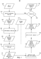
- Figure 1 illustrates a data flow diagram of a method for performing a full-waveform inversion in the traveltime domain in accordance with implementations of various techniques described herein.
- an earth model 105 is input into a seismic modeling module 115.
- the earth model 105 may be obtained using conventional seismic data processing techniques, such as velocity analysis, reflection or refraction tomography, extrapolation of well log information, statistical modeling, and the like.
- the earth model 105 represents the seismic properties of subterranean formations in the earth (e.g., P-wave velocity, density, S-wave velocity, seismic anisotropy parameters, seismic attenuation parameters) in a model space domain having spatial coordinates and depth or having spatial coordinates and traveltimes.
- the earth model may include acoustic properties of the subterranean formations in the earth such as velocities, densities, anisotropic and anelastic properties or elastic properties having a parameter that is a function of a shear modulus.
- the earth model 105 may also include parameters that describe the velocity of seismic wave propagation. The parameters may be updated at every physical scale represented by in the earth model.
- the model space domain of the earth model 105 may depend on how the earth model 105 has been obtained.
- the earth model 105 expressed in terms of spatial coordinates (e.g., x, y coordinates) and depth (e.g., z coordinate) may be referred to as an earth model in depth.
- the earth model in depth may represent the seismic properties of subterranean formations in the earth at various depths of the earth.
- the earth model 105 expressed in terms of spatial coordinates and traveltimes may be referred to as an earth model in traveltime.
- the traveltime may represent an amount of time between when a seismic wave travels from its source to a receiver such that the seismic wave has reflected from a subsurface interface.
- the receiver may be located relatively near the source.
- the method includes receiving seismic data acquired from one or more seismic receivers in a seismic survey, which may be referred to as seismic data 110.
- the seismic data 110 may contain seismic responses to seismic sources such as seismic reflection traveltimes.
- the seismic data 110 may be obtained from the relatively same geographical area of the earth in which the earth model 105 represents.
- the seismic data 110 may be presented in a data space domain defined by the location of the seismic receivers and either a time coordinate or a transform thereof, such as temporal frequency.
- the seismic data 110 may also be presented in a time or frequency domain.
- the seismic modeling module 115 uses earth model 105 to predict the seismic data or seismic responses that may have been obtained in the area of the earth defined in the earth model 105. This may be accomplished by finding the numerical solution of a wave-equation.
- the earth model 105 may be designated as a current earth model in traveltime. If, however, the earth model 105 is represented in the model space having spatial coordinates and depth, the seismic modeling module 115 may transform the earth model 105 via an inverse of the time-to-depth function into the current earth model in traveltime.
- the time-to-depth function converts earth models parameterized by traveltime into earth models parameterized by depth.
- the time-to-depth function maps properties in the earth model in traveltime to properties in the earth model in depth via time-to-depth curves.
- the depth-to-time curves are monotonically increasing functions.
- Linear interpolation may be used to preserve the monotonicity of the function, and fine-sampling in ⁇ may be used to ensure it is sufficiently accurate.
- the time-to-depth function may be linearized such that the gradients with the Jacobian can be calculated for a back propagation module 135, which will be described in more detail in the paragraphs below.
- the linearization of this function has two terms.
- the first term is a local contribution: a perturbation in earth model parameters in time that causes a similar perturbation in the depth model.
- the second term is a non-local contribution: a perturbation in velocity that will cause a perturbation at any point below where there is a contrast in earth model properties.
- the second term will (partially) cancel non-local terms in the seismic modeling, leaving the modeled data sensitive to local earth model perturbations.
- the seismic modeling module 115 may then convert the current earth model in traveltime into a current earth model in depth. In one implementation, converting the current earth model in traveltime into the current earth model in depth may be done by vertically stretching the data in the current earth model in traveltime based on the vertical P-wave velocity. Upon obtaining the current earth model in depth, the seismic modeling module 115 may simulate the seismic data that may have been obtained from the geographical area of the earth represented in the current earth model in depth. The output of the seismic modeling module 115 is a simulated seismic data or predicted seismic data 120.
- the predicted seismic data 120 may be in the same data-space domain as the seismic data 110 as described above (i.e., defined by the location of the seismic receivers and either a time coordinate or a transform thereof, such as temporal frequency).
- the predicted seismic data may include multiple reflections and reverberations with respect to the earth model 105.
- the seismic data 110 and the predicted seismic data 120 are then input into a difference module 125 in order to determine the differences between the seismic data 110 and the predicted seismic data 120.
- the difference module 125 may subtract the seismic data 110 from the predicted seismic data 120.
- the difference module 125 may also apply some additional filtering or windowing to the seismic data 110 and the predicted seismic data 120.
- the output of the difference module 125 is a residual seismic data 130.
- the residual seismic data 130 represents the differences between the seismic data 110 and the predicted seismic data 120.
- a norm/metric of the residual seismic data 130 may be described as the misfit, E, between the seismic data 110 and the predicted seismic data 120.
- the method described here in Figure 1 is based on minimizing a misfit, E , between the seismic data 110 ( d ) and the predicted seismic data 120 ( f ( m )) with respect to the current earth model ( m ) .
- the residual seismic data 130 is then input into a back propagation module 135.
- the back propagation module 135 propagates the residual seismic data 130 backward in time in the current earth model in depth to produce a back-propagating wavefield of the residual seismic data 130.
- the back propagation module 135 calculates a descent direction in depth by back projecting the residual seismic data 130 via the adjoint of the wave equation or via the adjoint of the Jacobian of the seismic modeling process, as described in the seismic modeling module 115 above.
- the back propagation module 135 then injects a model of the seismic sources into the current earth model in depth forward in time to produce a forward-propagating source wavefield.
- the back propagation module 135 cross-correlates the back-propagating wavefield of the residual seismic data 130 with the forward-propagating source wavefield.
- the partial derivatives describe the change in the predicted seismic data 120 with respect to a model parameter in depth.
- the resulting projection of the residual seismic data 130 into a model space is the earth model descent direction in depth 140.
- the earth model descent direction in depth 140 may be presented in the same space as the current earth model in depth, i.e. with spatial coordinates and depth.
- the descent direction of the earth model descent direction in depth 140 may be an estimate of the direction in model space from the current earth model in depth to an optimal earth model.
- the optimal earth model represents a more accurate earth model than the current earth model in depth.
- the earth model descent direction in depth 140 is then input into a depth-to-time translation module 145.
- the depth-to-time translation module 145 translates the depth coordinates of the earth model descent direction in depth 140 to traveltimes.
- the depth coordinates are translated to traveltimes by applying the adjoint of the Jacobian of the time-to-depth function to the earth model descent direction in depth 140.
- the time-to-depth function may be derived from a vertical integration of a vertical seismic traveltime or a zero-offset ray propagation.
- a spatial smoothing may be applied to the time-to-depth function in order to stabilize the time-to-depth function in one or more structurally complex areas.
- the output of the depth-to-time translation module 145 is an earth model descent direction in traveltime 150.
- a potential update to the seismic properties of the subterranean formations in the earth may be represented in the earth model descent direction in traveltime 150 in a model space having spatial coordinates and traveltimes.
- the earth model descent direction in traveltime 150 may be modified based on previous earth model descent directions in traveltime (for example via the Nonlinear Conjugate Gradients (NLCG) algorithm).
- the earth model descent direction in traveltime 150 may be modified by a preconditioning operator (for example, via an approximate inverse to the Hessian matrix). The purpose of modifying the earth model descent direction in traveltime 150 in either of these ways is to increase the rate of convergence in the corresponding earth model.
- the earth model descent direction in traveltime 150 may then be input into a step length module 155.
- the seismic data 110 may also be input into the step length module 155.
- the step length module 155 is used to update the current earth model in traveltime.
- the step length module 155 may obtain a direction in which the current earth model in traveltime will be updated and how far to go into that direction (i.e., appropriate step length).
- the direction in which the current earth model in traveltime will be updated may be the descent direction of the earth model descent direction in traveltime 140 as obtained from the back propagation module 135.
- the descent direction may be an estimate of the direction in model space from the current earth model in traveltime to the optimal earth model.
- the appropriate step length may describe an estimate of the distance in the descent direction to use in updating the Current Earth Model in Traveltime. As such, the appropriate step length may also be referred to as the distance.
- the appropriate step length may be embedded within the descent direction when the descent direction is determined using certain algorithms (e.g., Gauss-Newton). In these situations, an explicit step length calculation may be unnecessary and the step length module 155 may simply return 1 as the appropriate step length. In other implementations, the appropriate step length may be determined by the step length module 155 according to a process described in Figure 3 .
- the step length module 155 may multiply the appropriate step length with the earth model descent direction in traveltime 150 and add the resulting product to the current earth model in traveltime to create an updated earth model in traveltime 160.
- the product of the appropriate step length and the descent direction may define the amount in which the current earth model in traveltime will be updated.
- the earth model descent direction in traveltime 150 may have the same units/dimensions as the current earth model in traveltime, and the appropriate step length may be physically dimensionless. In this manner, the appropriate step length multiplied by the earth model descent direction in traveltime 150 may also have the same units as the current earth model in traveltime.
- the updated earth model in traveltime 160 may be input into an iteration module 165.
- the iteration module 165 may then designate the updated earth model in traveltime 160 as the current earth model in traveltime, and the process detailed in Figure 1 may be repeated iteratively until certain conditions are met.
- the conditions may include reaching a predetermined maximum number of iterations, obtaining an updated residual seismic data 130 such that it falls below a predetermined value, determining whether the updated earth model in traveltime 160 is within a specified tolerance of the current earth model in traveltime, and the like. If the conditions have not been met, the process detailed in Figure 1 may be repeated using the updated earth model in traveltime 160 instead of the earth model 105.
- the updated earth Model in traveltime 160 is input into the seismic modeling module 115 instead of the earth model 105. Accordingly, the updated earth model in traveltime 160 may be continuously updated to more accurately reflect the corresponding seismic properties of subterranean formations in the earth.
- the iteration module 165 may exit the iterative process exits and may translate the current earth model in traveltime into a current earth model in depth to produce a final earth model in depth 170.
- the final earth model in depth 170 may then be used to create seismic migration models, perform reservoir calculations, determine well exploration sites and the like.
- the final earth model in depth 170 has been described as being in the model space having spatial coordinates and depth, it should be noted that in some implementations, the final earth model may be presented in the model space having spatial coordinates and traveltimes.
- the method for performing a full-waveform inversion in the traveltime domain described herein is a one-step process that inverts for velocity and impedance simultaneously (e.g., as a function of traveltime).
- the method for performing a full-waveform inversion does not just invert for acoustic impedance as a function of traveltime, and velocity is not explicitly held constant.
- Snieder, Xie, Pica and Tarantola's description of the implementation of their algorithm performs the inversion for impedance using a Born inversion of the near offset trace as opposed to a full-waveform method as described herein.
- Sevink and Herman describe another two step approach for seismic inversion with both steps of for seismic inversion for high-frequency "contrast” and low frequency velocity which are parameterized by a traveltime metric.
- the Sevink and Herman method differs from the method for performing a full-waveform inversion described herein in that Sevink and Herman's forward modeling is done with an asymptotic Born algorithm that ignores multiple scattering and reverberations.
- Sevink and Herman's defines a low frequency velocity model according to a very low-order parameterization.
- Steps 140 and 145 provide flexibility in development and application of the full-waveform inversion.
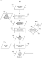
- Figure 2 illustrates a data flow diagram of a method for estimating a step length in accordance with one or more implementations of various techniques described herein.
- the step length module 155 may first determine a trial step length 210.
- the trial step length 210 may be generated by the step length module 155 in a number of different ways.
- the initial step length may be a prescribed percentage of the ratio between an L2 norm of the descent direction and an L2 norm of the current earth model.
- the trial step length 210 may initially be set to a value of 1.
- the trial step length 210 may also be referred to as the trial distance.
- the trial step length 210 may be input into an earth model update module 220.
- the earth model update module 220 may multiply the trial step length 210 with the earth model descent direction in traveltime 150 obtained from the depth-to-time translation module 145 as described in Figure 1 .
- the earth model update module 220 may add the product to the current earth model in traveltime. The sum resulting from this addition may be referred to as a trial updated earth model in traveltime 230.
- the trial updated earth model in traveltime 230 may then be input into a trial seismic modeling module 240.
- the trial seismic modeling module 240 may be functionally similar to the seismic modeling module 115 as described in Figure 1 . As such, the trial seismic modeling module 240 may first convert the trial updated earth model in traveltime 230 into a trial updated earth model in depth. According to the method described with reference to the seismic modeling module 115, the trial seismic modeling module 240 may then simulate or predict the seismic data that may have been obtained in the geographical area defined by the trial updated earth model in depth. The output of the trial seismic modeling module 240 is the trial predicted seismic data 250.
- the trial predicted seismic data 250 is then input into a trial difference module 260.
- the trial difference module 260 may also receive the seismic data 110 as an input.
- the trial difference module 260 may then subtract the seismic data 110 from the trial predicted seismic data 250 which may use a similar process to calculate a trial residual seismic data 270 as described in the difference module 125 in Figure 1 .
- the output of the trial difference module 260 is the trial residual seismic data 270.
- the trial residual seismic data 270 may also be referred to as the trial difference.
- the trial residual seismic data 270 may then be input into an appropriate step length module 280 to determine whether the trial step length 210 is an appropriate step length to use in updating the current earth model in traveltime.
- the appropriate step length module 280 may determine that the trial step length 210 is an appropriate step length by determining whether certain conditions have been met. Examples of when conditions are met include when the norm of the trial residual seismic data 270 falls below a predetermined value, when the trial updated earth model in traveltime 230 is within a specified tolerance from the current earth model in traveltime, and the like.
- a new trial step length 210 will be generated by the step length module 155 and the process described in Figure 2 will then be repeated using the different trial step length 210.
- the new trial step length 210 may be generated by increasing, decreasing or by altering the previous trial step length 210 in some manner.
- the process defined in Figure 2 may then continue until the step length module 280 deems the trial step length 210 as an appropriate step length.
- the appropriate step length module 280 may set the trial step length 210 as the step length 290.
- the step length 290 may then be used by the step length module 155 described in Figure 1 as the appropriate step length.
- Figure 3A illustrates full-waveform inversion in traveltime results as compared to conventional full-waveform inversion results in accordance with one or more implementations of various techniques described herein.
- line 310 illustrates a true one-dimensional (1D) velocity profile that was used to generate a synthetic shot-gather data via two-dimensional (2D) finite-differences. As such, line 310 represents an ideal model that is to be reconstructed using full-waveform inversion.
- Line 320 corresponds to the velocity profile of the earth model 105 as described in Figure 1 .
- Line 330 represents the updated earth model after 50 iterations using a conventional FWI approach.
- Line 340 represents the updated earth model after 50 iterations using the FWI in traveltime domain as described in Figure 1 . As indicated in Figure 3 , using the FWI in traveltime domain (line 340) more accurately reconstructs the earth model (line 320) to appear like the true velocity profile (line 310) than the conventional FWI method (line 330).
- Figure 3B illustrates the residual errors over the number of iterations from using a conventional FWI process and the residual errors over the number of iterations from using a FWI process in the traveltime domain in accordance with one or more implementations of various techniques described herein.
- Line 350 represents the residual errors for a conventional FWI method over the number of iterations.
- Line 360 represents the residual errors for a FWI method using traveltimes over the number of iterations.
- the FWI method using traveltimes has significantly lowered residual values than the conventional FWI method. As such, there is a closer fit between the true velocity profile (line 310) and the predicted velocity profile (line 340). The convergence of line 360 is also significantly faster than the conventional FWI method. Therefore, fewer iterations may be required to obtain a more accurate predicted velocity profile.
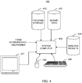
- FIG. 4 illustrates a computer network 400 into which implementations of various technologies described herein may be implemented.
- various techniques for performing a full-waveform inversion in the traveltime domain as described in Figures 1-2 may be performed on the computer network 400.
- the computer network 400 may include a system computer 430, which may be implemented as any conventional personal computer or server.
- system computer 430 may be implemented as any conventional personal computer or server.
- implementations of various technologies described herein may be practiced in other computer system configurations, including hypertext transfer protocol (HTTP) servers, hand-held devices, multiprocessor systems, microprocessor-based or programmable consumer electronics, network PCs, minicomputers, mainframe computers, high-performance clusters of computers, co-processing-based systems (GPUs, FPGAs) and the like.
- HTTP hypertext transfer protocol
- the system computer 430 may be in communication with disk storage devices 429, 431, and 433, which may be external hard disk storage devices. It is contemplated that disk storage devices 429, 431, and 433 are conventional hard disk drives, and as such, will be implemented by way of a local area network or by remote access. Of course, while disk storage devices 429, 431, and 433 are illustrated as separate devices, a single disk storage device may be used to store any and all of the program instructions, measurement data, and results as desired.
- seismic data from the receivers may be stored in disk storage device 431.
- the system computer 430 may retrieve the appropriate data from the disk storage device 431 to process seismic data according to program instructions that correspond to implementations of various technologies described herein.
- Seismic data may include pressure and particle velocity data.
- the program instructions may be written in a computer programming language, such as C++, Java and the like.
- the program instructions may be stored in a computer-readable memory, such as program disk storage device 433.
- Such computer-readable media may include computer storage media and communication media.
- Computer storage media may include volatile and non-volatile, and removable and non-removable media implemented in any method or technology for storage of information, such as computer-readable instructions, data structures, program modules or other data.
- Computer storage media may further include RAM, ROM, erasable programmable read-only memory (EPROM), electrically erasable programmable read-only memory (EEPROM), flash memory or other solid state memory technology, CD-ROM, digital versatile disks (DVD), or other optical storage, magnetic cassettes, magnetic tape, magnetic disk storage or other magnetic storage devices, or any other medium which can be used to store the desired information and which can be accessed by the computing system 400.
- Communication media may embody computer readable instructions, data structures, program modules or other data in a modulated data signal, such as a carrier wave or other transport mechanism and may include any information delivery media.
- modulated data signal may mean a signal that has one or more of its characteristics set or changed in such a manner as to encode information in the signal.
- communication media may include wired media such as a wired network or direct-wired connection, and wireless media such as acoustic, RF, infrared and other wireless media. Combinations of the any of the above may also be included within the scope of computer readable media.
- system computer 430 may present output primarily onto graphics display 427.
- the system computer 430 may store the results of the methods described above on disk storage 429, for later use and further analysis.
- the keyboard 426 and the pointing device (e.g., a mouse, trackball, or the like) 425 may be provided with the system computer 430 to enable interactive operation.
- the system computer 430 may be located at a data center remote from the survey region.
- the system computer 430 may be in communication with the receivers (either directly or via a recording unit, not shown), to receive signals indicative of the reflected seismic energy. After conventional formatting and other initial processing, these signals may be stored by the system computer 430 as digital data in the disk storage 431 for subsequent retrieval and processing in the manner described above. While Figure 4 illustrates the disk storage 431 as directly connected to the system computer 430, it is also contemplated that the disk storage device 431 may be accessible through a local area network or by remote access.
- disk storage devices 429, 431 are illustrated as separate devices for storing input seismic data and analysis results, the disk storage devices 429, 431 may be implemented within a single disk drive (either together with or separately from program disk storage device 433), or in any other conventional manner as will be fully understood by one of skill in the art having reference to this specification.
Landscapes
- Engineering & Computer Science (AREA)
- Remote Sensing (AREA)
- Physics & Mathematics (AREA)
- Life Sciences & Earth Sciences (AREA)
- Acoustics & Sound (AREA)
- Environmental & Geological Engineering (AREA)
- Geology (AREA)
- General Life Sciences & Earth Sciences (AREA)
- General Physics & Mathematics (AREA)
- Geophysics (AREA)
- Geophysics And Detection Of Objects (AREA)
Claims (10)
- Procédé pour le traitement de données sismiques, comprenant :a) la prédiction de données sismiques (120) sur la base d'un modèle terrestre (105) qui représente des propriétés sismiques de formations souterraines dans la terre en déterminant qu'un modèle terrestre est un modèle terrestre en profondeur, en simulant des données sismiques conformément au modèle terrestre en profondeur et en convertissant le modèle terrestre en profondeur selon un modèle terrestre en temps de trajet ;b) la détermination d'une différence (130) entre des données sismiques (110) qui sont acquises à partir d'un ou de plusieurs récepteur(s) sismique(s) et les données sismiques prédites (120) ;c) la projection de la différence (130) suivant une direction de descente de modèle terrestre en profondeur (140) en injectant un modèle d'une ou de plusieurs source(s) sismique(s) à l'intérieur du modèle terrestre en profondeur vers l'avant dans le temps de manière à produire un champ d'ondes de source se propageant vers l'avant, en produisant la direction de descente de modèle terrestre en profondeur en effectuant une corrélation croisée d'un champ d'ondes propagé vers l'arrière de la différence avec le champ d'ondes de source propagé vers l'avant et en transposant la direction de descente de modèle terrestre en profondeur (140), en utilisant au moins un processeur, selon une direction de descente de modèle terrestre en temps de trajet (150) ; etd) la mise à jour, en utilisant l'au moins un processeur, du modèle terrestre en temps de trajet conformément à la direction de descente de modèle terrestre en temps de trajet, dans lequel le modèle terrestre en temps de trajet mis à jour (160) représente de manière davantage précise les propriétés sismiques des formations souterraines dans la terre ; et
caractérisé en ce que :la transposition de la direction de descente de modèle terrestre en profondeur (140) comprend l'application d'un opérateur adjoint d'une jacobienne d'une fonction temps-profondeur à la direction de descente de modèle terrestre en profondeur, dans lequel la fonction temps-profondeur convertit des modèle terrestres paramétrés par temps de trajet selon des modèle terrestres paramétrés par profondeur. - Procédé selon la revendication 1, dans lequel la fonction temps-profondeur est dérivée à partir d'une intégration verticale d'un temps de trajet sismique vertical ou d'une propagation de rayons à décalage zéro.
- Procédé selon la revendication 1, dans lequel la mise à jour du modèle terrestre en temps de trajet comprend :la détermination d'une distance dans une direction pour mettre à jour le modèle terrestre en temps de trajet ;le calcul d'un produit de la distance et de la direction de descente de modèle terrestre en temps de trajet ; etl'addition du produit au modèle terrestre en temps de trajet.
- Procédé selon la revendication 3, dans lequel la détermination de la distance comprend :la génération d'une distance d'essai ;le calcul d'un produit de la distance d'essai et de la direction de descente de modèle terrestre en temps de trajet ;l'addition du produit de la distance d'essai et de la direction de descente de modèle terrestre en temps de trajet au modèle terrestre en temps de trajet de manière à créer un modèle terrestre mis à jour d'essai ;la prédiction de données sismiques d'essai conformément au modèle terrestre mis à jour d'essai ;la détermination d'une différence d'essai entre les données sismiques acquises et les données sismiques d'essai prédites ; etla détermination de la distance d'essai comme étant la distance, lorsque la différence d'essai chute au-dessous d'une valeur prédéterminée.
- Procédé selon la revendication 1, comprenant en outre la répétition des étapes a) à d) en utilisant le modèle terrestre mis à jour en tant que modèle terrestre jusqu'à ce qu'une ou plusieurs condition(s) prédéterminée(s) soi(en)t satisfaite(s), dans lequel les conditions prédéterminées comprennent :l'atteinte d'un nombre d'itérations maximum prédéterminé ;la détermination du fait que la différence chute au-dessous d'une valeur prédéterminée ;la détermination du fait que le modèle terrestre en temps de trajet mis à jour est à l'intérieur d'une tolérance spécifique du modèle terrestre en temps de trajet ; oudes combinaisons afférentes.
- Procédé selon la revendication 1, dans lequel la détermination de la différence comprend en outre :l'application d'un filtre ou d'une fenêtre aux données sismiques acquises et aux données sismiques prédites ; oul'utilisation d'un procédé par les moindres carrés ; oul'utilisation de données sismiques résiduelles.
- Procédé selon la revendication 1, dans lequel les données sismiques (110) sont des temps de trajet de réflexion sismique et dans lequel les données sismiques (110) sont dans un domaine temporel ou dans un domaine des fréquences.
- Procédé selon la revendication 1, dans lequel le modèle terrestre en temps de trajet (105) comprend :une ou plusieurs propriété(s) acoustique(s) comportant des vitesses, des densités ou des combinaisons afférentes ;une ou plusieurs propriété(s) élastique(s) comportant un paramètre qui est une fonction d'un module de cisaillement ;une ou plusieurs propriété(s) anisotrope(s) ;une ou plusieurs propriété(s) anélastique(s) ; oudes combinaisons afférentes.
- Procédé selon la revendication 1, dans lequel le modèle terrestre en temps de trajet (105) comprend un ou plusieurs paramètre(s) qui décrit/décrivent une ou plusieurs vitesse(s) de propagation d'ondes sismiques.
- Système informatique, comprenant :un processeur ; etune mémoire qui comprend des instructions de programme qui peuvent être exécutées par le processeur pour réaliser un procédé tel que revendiqué selon les revendications 1 à 9.
Applications Claiming Priority (2)
| Application Number | Priority Date | Filing Date | Title |
|---|---|---|---|
| US12/581,372 US9244181B2 (en) | 2009-10-19 | 2009-10-19 | Full-waveform inversion in the traveltime domain |
| PCT/US2010/053083 WO2011049885A2 (fr) | 2009-10-19 | 2010-10-18 | Inversion de forme d'onde complète dans le domaine du temps de trajet |
Publications (3)
| Publication Number | Publication Date |
|---|---|
| EP2491428A2 EP2491428A2 (fr) | 2012-08-29 |
| EP2491428A4 EP2491428A4 (fr) | 2014-08-06 |
| EP2491428B1 true EP2491428B1 (fr) | 2017-12-13 |
Family
ID=43879194
Family Applications (1)
| Application Number | Title | Priority Date | Filing Date |
|---|---|---|---|
| EP10825480.6A Active EP2491428B1 (fr) | 2009-10-19 | 2010-10-18 | Inversion de forme d'onde complète dans le domaine du temps de trajet |
Country Status (4)
| Country | Link |
|---|---|
| US (1) | US9244181B2 (fr) |
| EP (1) | EP2491428B1 (fr) |
| NO (1) | NO2491428T3 (fr) |
| WO (1) | WO2011049885A2 (fr) |
Cited By (1)
| Publication number | Priority date | Publication date | Assignee | Title |
|---|---|---|---|---|
| RU2674524C1 (ru) * | 2018-03-28 | 2018-12-11 | Григорий Аронович Шехтман | Способ сейсмической разведки |
Families Citing this family (74)
| Publication number | Priority date | Publication date | Assignee | Title |
|---|---|---|---|---|
| US8694299B2 (en) | 2010-05-07 | 2014-04-08 | Exxonmobil Upstream Research Company | Artifact reduction in iterative inversion of geophysical data |
| GB2497055A (en) * | 2010-09-28 | 2013-05-29 | Shell Int Research | Earth model estimation through an acoustic full waveform inversion of seismic data |
| WO2012100153A1 (fr) * | 2011-01-20 | 2012-07-26 | Northeastern University | Système de détection de profil de trottoir en temps réel utilisant une onde de surface à couplage à l'air |
| EP2691795A4 (fr) | 2011-03-30 | 2015-12-09 | Vitesse de convergence d'une inversion d'un champ d'onde complet utilisant une mise en forme spectrale | |
| SG193233A1 (en) * | 2011-03-31 | 2013-10-30 | Exxonmobil Upstream Res Co | Method of wavelet estimation and multiple prediction in full wavefield inversion |
| US9158018B2 (en) | 2011-04-05 | 2015-10-13 | Westerngeco L.L.C. | Waveform inversion using a response of forward modeling |
| US20120316790A1 (en) * | 2011-06-08 | 2012-12-13 | Chevron U.S.A. Inc. | System and method for data inversion with phase extrapolation |
| US9075159B2 (en) | 2011-06-08 | 2015-07-07 | Chevron U.S.A., Inc. | System and method for seismic data inversion |
| US20120316791A1 (en) * | 2011-06-08 | 2012-12-13 | Chevron U.S.A. Inc. | System and method for seismic data inversion by non-linear model update |
| US9702995B2 (en) | 2011-06-17 | 2017-07-11 | Exxonmobil Upstream Research Company | Domain freezing in joint inversion |
| WO2013032573A2 (fr) | 2011-09-02 | 2013-03-07 | Exxonmobil Upstream Research Company | Utilisation d'une projection sur des ensembles convexes pour limiter l'inversion du champ d'ondes complet |
| US9176930B2 (en) * | 2011-11-29 | 2015-11-03 | Exxonmobil Upstream Research Company | Methods for approximating hessian times vector operation in full wavefield inversion |
| WO2013105074A1 (fr) * | 2012-01-13 | 2013-07-18 | Geco Technology B.V. | Inversion de forme d'onde basée sur surface 3d |
| US9121964B2 (en) * | 2012-01-13 | 2015-09-01 | Westerngeco L.L.C. | Parameterizing a geological subsurface feature |
| CN104204857B (zh) | 2012-03-08 | 2017-12-08 | 埃克森美孚上游研究公司 | 正交源和接收器编码 |
| AU2013353472B2 (en) | 2012-11-28 | 2016-09-22 | Exxonmobil Upstream Research Company | Reflection seismic data Q tomography |
| US20140200812A1 (en) * | 2013-01-11 | 2014-07-17 | Westerngeco L.L.C. | Processing survey data for determining a wavefield |
| FR3001042B1 (fr) * | 2013-01-16 | 2015-07-31 | Cggveritas Services Sa | Acquisition de flutes remorquees avec une resolution spatiale variable |
| US9696445B2 (en) * | 2013-03-14 | 2017-07-04 | Pgs Geophysical As | Systems and methods for frequency-domain filtering and space-time domain discrimination of seismic data |
| US10429530B2 (en) | 2013-04-29 | 2019-10-01 | Westerngeco L.L.C. | Deghosting with adaptive operators |
| US9575194B2 (en) * | 2013-05-01 | 2017-02-21 | Cgg Services Sas | Method apparatus and system for migration noise attenuation and image enhancement |
| CN105308479B (zh) | 2013-05-24 | 2017-09-26 | 埃克森美孚上游研究公司 | 通过与偏移距相关的弹性fwi的多参数反演 |
| US10459117B2 (en) | 2013-06-03 | 2019-10-29 | Exxonmobil Upstream Research Company | Extended subspace method for cross-talk mitigation in multi-parameter inversion |
| US9702998B2 (en) | 2013-07-08 | 2017-07-11 | Exxonmobil Upstream Research Company | Full-wavefield inversion of primaries and multiples in marine environment |
| EP3036566B1 (fr) | 2013-08-23 | 2018-04-04 | Exxonmobil Upstream Research Company | Recherche simultanée de sources pendant une acquisition sismique et une inversion sismique |
| US10036818B2 (en) | 2013-09-06 | 2018-07-31 | Exxonmobil Upstream Research Company | Accelerating full wavefield inversion with nonstationary point-spread functions |
| US9910189B2 (en) | 2014-04-09 | 2018-03-06 | Exxonmobil Upstream Research Company | Method for fast line search in frequency domain FWI |
| WO2015171215A1 (fr) | 2014-05-09 | 2015-11-12 | Exxonmobil Upstream Research Company | Procédés efficaces de recherche du pas optimal pour inversion de champ d'ondes complet à paramètres multiples |
| US10185046B2 (en) | 2014-06-09 | 2019-01-22 | Exxonmobil Upstream Research Company | Method for temporal dispersion correction for seismic simulation, RTM and FWI |
| RU2016150545A (ru) | 2014-06-17 | 2018-07-17 | Эксонмобил Апстрим Рисерч Компани | Быстрая вязкоакустическая и вязкоупругая инверсия полного волнового поля |
| US10838092B2 (en) | 2014-07-24 | 2020-11-17 | Exxonmobil Upstream Research Company | Estimating multiple subsurface parameters by cascaded inversion of wavefield components |
| US10422899B2 (en) | 2014-07-30 | 2019-09-24 | Exxonmobil Upstream Research Company | Harmonic encoding for FWI |
| WO2016046633A1 (fr) * | 2014-09-22 | 2016-03-31 | Cgg Services Sa | Inversion simultanée de formes d'onde complètes répétitives de multiples millésimes |
| US10386511B2 (en) | 2014-10-03 | 2019-08-20 | Exxonmobil Upstream Research Company | Seismic survey design using full wavefield inversion |
| MY182815A (en) | 2014-10-20 | 2021-02-05 | Exxonmobil Upstream Res Co | Velocity tomography using property scans |
| WO2016065247A1 (fr) * | 2014-10-24 | 2016-04-28 | Westerngeco Llc | Fonction objective de temps de déplacement pour inversion de forme d'onde complète |
| WO2016099747A1 (fr) * | 2014-12-18 | 2016-06-23 | Exxonmobil Upstream Research Company | Planification évolutive de travaux sismiques itératifs parallèles |
| US9864083B2 (en) * | 2015-01-23 | 2018-01-09 | Advanced Geophysical Technology, Inc. | Beat tone full waveform inversion |
| US10520618B2 (en) | 2015-02-04 | 2019-12-31 | ExxohnMobil Upstream Research Company | Poynting vector minimal reflection boundary conditions |
| CA2972028C (fr) | 2015-02-13 | 2019-08-13 | Exxonmobil Upstream Research Company | Condition de limite d'absorption efficace et stable dans des calculs a difference finie |
| CA2972033C (fr) | 2015-02-17 | 2019-07-23 | Exxonmobil Upstream Research Company | Procede d'inversion de champ d'ondes complet a plusieurs etages qui genere un ensemble de donnees sans multiples |
| WO2016154404A1 (fr) * | 2015-03-26 | 2016-09-29 | Schlumberger Technology Corporation | Inversion de forme d'onde sismique |
| EP3073296B1 (fr) * | 2015-03-27 | 2020-09-23 | CGG Services SAS | Procédé d'inversion de forme d'onde complète pour traiter des données sismiques par migration temporelle inverse d'amplitude préservée |
| RU2017145541A (ru) | 2015-06-04 | 2019-07-09 | Эксонмобил Апстрим Рисерч Компани | Способ построения свободных от многократных волн сейсмических изображений |
| US10838093B2 (en) | 2015-07-02 | 2020-11-17 | Exxonmobil Upstream Research Company | Krylov-space-based quasi-newton preconditioner for full-wavefield inversion |
| US10768322B2 (en) * | 2015-08-27 | 2020-09-08 | Pgs Geophysical As | Analogous processing of modeled and measured marine survey data |
| RU2693495C1 (ru) | 2015-10-02 | 2019-07-03 | Эксонмобил Апстрим Рисерч Компани | Полная инверсия волнового поля с компенсацией показателя качества |
| MX2018003495A (es) | 2015-10-15 | 2018-06-06 | Exxonmobil Upstream Res Co | Apilados angulares de dominio de modelo de fwi con conservacion de amplitud. |
| EP3168653B1 (fr) * | 2015-11-05 | 2019-07-17 | CGG Services SAS | Dispositif et procédé d'inversion de forme d'onde complète |
| WO2017100746A1 (fr) * | 2015-12-11 | 2017-06-15 | Ion Geophysical Corporation | Système et procédé pour inversion de champ d'ondes reconstruit |
| CN108369289A (zh) * | 2015-12-18 | 2018-08-03 | 埃克森美孚上游研究公司 | 使用全波场反演点扩展函数分析设计地球物理勘测的方法 |
| US10768324B2 (en) | 2016-05-19 | 2020-09-08 | Exxonmobil Upstream Research Company | Method to predict pore pressure and seal integrity using full wavefield inversion |
| WO2018004789A1 (fr) * | 2016-06-28 | 2018-01-04 | Exxonbil Upstream Research Company | Migration en temps inverse dans des milieux anisotropes avec compensation d'atténuation stable |
| EP3559707B1 (fr) | 2016-12-20 | 2021-02-17 | ION Geophysical Corporation | Système et procédé permettant une imagerie de champ d'ondes reconstruit |
| US11487036B2 (en) * | 2017-01-12 | 2022-11-01 | Cgg Services Sas | Reflection full waveform inversion methods with density and velocity models updated separately |
| US10656294B2 (en) | 2017-05-17 | 2020-05-19 | Saudi Arabian Oil Company | Generating a velocity model using subsurface azimuth and reflection angle dependent full waveform inversion |
| US11269097B2 (en) | 2017-05-22 | 2022-03-08 | Saudi Arabian Oil Company | Computing amplitude independent gradient for seismic velocity inversion in a frequency domain |
| WO2018217875A1 (fr) * | 2017-05-23 | 2018-11-29 | Schlumberger Technology Corporation | Système d'interprétation de données sismiques facilitée par des données analogues |
| CN107422379B (zh) * | 2017-07-27 | 2019-01-11 | 中国海洋石油集团有限公司 | 基于局部自适应凸化方法的多尺度地震全波形反演方法 |
| WO2019038726A1 (fr) * | 2017-08-24 | 2019-02-28 | Chevron U.S.A. Inc. | Système et procédé d'inversion de forme d'onde complète dans le domaine de l'image |
| US10948617B2 (en) | 2017-12-11 | 2021-03-16 | Saudi Arabian Oil Company | Generating a velocity model for a subsurface structure using refraction travel time tomography |
| GB2573152B (en) * | 2018-04-26 | 2020-05-27 | Equinor Energy As | Providing for uncertainty in non-linear inversions of geophysical data |
| AU2019290138B2 (en) | 2018-06-20 | 2024-07-11 | Pgs Geophysical As | Long-offset acquisition |
| WO2020149962A1 (fr) * | 2019-01-18 | 2020-07-23 | Exxonmobil Research And Engineering Company | Estimation de propriétés d'écoulement de réservoir à partir de données sismiques |
| EP3990949B1 (fr) | 2019-06-28 | 2025-05-21 | Services Pétroliers Schlumberger | Acquisition de données de champ |
| US12182727B2 (en) | 2019-08-16 | 2024-12-31 | Miguel Eduardo Bosch Blumenfeld | Localized full waveform inversion using synthetic energy focusing |
| CN112444848B (zh) * | 2019-08-29 | 2024-01-23 | 中国石油化工股份有限公司 | 一种全波形反演的方法及系统 |
| US12105240B2 (en) | 2019-10-28 | 2024-10-01 | Pgs Geophysical As | Long-offset acquisition with improved low frequency performance for full wavefield inversion |
| US12072461B2 (en) | 2019-10-28 | 2024-08-27 | Pgs Geophysical As | Modified simultaneous long-offset acquisition with improved low frequency performance for full wavefield inversion |
| CN115335729A (zh) * | 2020-02-27 | 2022-11-11 | 地质探索系统公司 | 模板匹配全波形反演 |
| US11320557B2 (en) | 2020-03-30 | 2022-05-03 | Saudi Arabian Oil Company | Post-stack time domain image with broadened spectrum |
| CN111766628A (zh) * | 2020-07-29 | 2020-10-13 | 浪潮云信息技术股份公司 | 一种预条件的时间域弹性介质多参数全波形反演方法 |
| CN114428307A (zh) * | 2020-10-10 | 2022-05-03 | 中国石油化工股份有限公司 | 一种地震多数据联合的三维速度建模方法及系统 |
| CN120745267B (zh) * | 2025-09-05 | 2025-11-07 | 自然资源部第一海洋研究所 | 一种结合数值模拟与实测数据的岸滩变化演进反演方法 |
Family Cites Families (12)
| Publication number | Priority date | Publication date | Assignee | Title |
|---|---|---|---|---|
| US4953142A (en) | 1989-01-06 | 1990-08-28 | Marathon Oil Company | Model-based depth processing of seismic data |
| US4953140A (en) | 1989-08-21 | 1990-08-28 | Mobil Oil Corporation | Method of subterranean mapping |
| US4964088A (en) * | 1989-10-31 | 1990-10-16 | Conoco Inc. | Method for tomographically laterally varying seismic data velocity estimation |
| US5233568A (en) * | 1991-06-28 | 1993-08-03 | Atlantic Richfield Company | Geopressure analysis system |
| US6925387B2 (en) * | 2003-08-14 | 2005-08-02 | Westerngeco L.L.C. | Method and apparatus for kinematically linking multiple seismic domains |
| US7117093B2 (en) * | 2004-03-02 | 2006-10-03 | Data Modeling Inc. | Method, media, and signals for processing seismic data to obtain a velocity field |
| US7167414B2 (en) * | 2004-10-04 | 2007-01-23 | Pgs Americas, Inc. | Amplitude preserving prestack migration method |
| FR2886740B1 (fr) * | 2005-06-03 | 2007-09-28 | Inst Francais Du Petrole | Methode pour mettre a jour un modele geologique par des donnees sismiques et de production |
| US20070104028A1 (en) * | 2005-11-04 | 2007-05-10 | Dirk-Jan Van Manen | Construction and removal of scattered ground roll using interferometric methods |
| US7373252B2 (en) | 2005-11-04 | 2008-05-13 | Western Geco L.L.C. | 3D pre-stack full waveform inversion |
| US7196969B1 (en) | 2006-02-09 | 2007-03-27 | Pgs Geophysical As | Three-dimensional two-way acoustic wave equation pre-stack imaging systems and methods |
| US7663972B2 (en) * | 2008-02-22 | 2010-02-16 | Pgs Geophysical As | Method for three dimensional seismic travel time tomography in transversely isotropic media |
-
2009
- 2009-10-19 US US12/581,372 patent/US9244181B2/en active Active
-
2010
- 2010-10-18 EP EP10825480.6A patent/EP2491428B1/fr active Active
- 2010-10-18 WO PCT/US2010/053083 patent/WO2011049885A2/fr not_active Ceased
- 2010-10-18 NO NO10825480A patent/NO2491428T3/no unknown
Cited By (1)
| Publication number | Priority date | Publication date | Assignee | Title |
|---|---|---|---|---|
| RU2674524C1 (ru) * | 2018-03-28 | 2018-12-11 | Григорий Аронович Шехтман | Способ сейсмической разведки |
Also Published As
| Publication number | Publication date |
|---|---|
| EP2491428A4 (fr) | 2014-08-06 |
| NO2491428T3 (fr) | 2018-05-12 |
| WO2011049885A2 (fr) | 2011-04-28 |
| WO2011049885A3 (fr) | 2011-09-01 |
| US20110090760A1 (en) | 2011-04-21 |
| EP2491428A2 (fr) | 2012-08-29 |
| US9244181B2 (en) | 2016-01-26 |
Similar Documents
| Publication | Publication Date | Title |
|---|---|---|
| US9244181B2 (en) | Full-waveform inversion in the traveltime domain | |
| US8352190B2 (en) | Method for analyzing multiple geophysical data sets | |
| US11378704B2 (en) | Method for generating an image of a subsurface of an area of interest from seismic data | |
| RU2693495C1 (ru) | Полная инверсия волнового поля с компенсацией показателя качества | |
| CN113740901B (zh) | 基于复杂起伏地表的陆上地震数据全波形反演方法及装置 | |
| CN102892972B (zh) | 地球物理数据的迭代反演中的伪迹减少 | |
| EP2810101B1 (fr) | Amélioration de l'efficacité d'algorithmes d'inversion à base de pixels | |
| US9829592B2 (en) | Seismic imaging with visco-acoustic reverse-time migration using pseudo-analytical method | |
| US11867856B2 (en) | Method and system for reflection-based travel time inversion using segment dynamic image warping | |
| US11733413B2 (en) | Method and system for super resolution least-squares reverse time migration | |
| US10768324B2 (en) | Method to predict pore pressure and seal integrity using full wavefield inversion | |
| US20090213692A1 (en) | Method for three dimensional seismic travel time tomography in transversely isotropic media | |
| US9335430B2 (en) | Wave field separation by mixed domain inversion | |
| CN103270430A (zh) | 用于地震数据反演的系统和方法 | |
| US10739481B2 (en) | 2D multiline seismic reflection tomography with seismic-tie constraint | |
| AU2012268720A1 (en) | System and method for data inversion with phase extrapolation | |
| François et al. | Frequency‐domain modelling and inversion of electromagnetic data for 2D permittivity and conductivity imaging: An application to the Institut Fresnel experimental dataset | |
| Aghazade et al. | Fast and automatic full waveform inversion by dual augmented Lagrangian | |
| CN115032694B (zh) | 一种vsp初至旅行时层析成像方法及系统 | |
| Park et al. | Refraction traveltime tomography based on damped wave equation for irregular topographic model | |
| EP4488724A1 (fr) | Système et procédé de migration des moindres carrés de données sismiques répétitives | |
| Xiang et al. | A matrix‐free variant of the distorted Born iterative method for seismic full‐waveform inversion | |
| WO2015124960A1 (fr) | Systèmes et procédés permettant une meilleure analyse d'inversion de données sismiques | |
| Wang et al. | Full waveform inversion in fractured media based on velocity–stress wave equations in the time domain | |
| Basit et al. | Diving wave tomography: Velocity modelling using first arrival traveltime |
Legal Events
| Date | Code | Title | Description |
|---|---|---|---|
| PUAI | Public reference made under article 153(3) epc to a published international application that has entered the european phase |
Free format text: ORIGINAL CODE: 0009012 |
|
| 17P | Request for examination filed |
Effective date: 20120510 |
|
| AK | Designated contracting states |
Kind code of ref document: A2 Designated state(s): AL AT BE BG CH CY CZ DE DK EE ES FI FR GB GR HR HU IE IS IT LI LT LU LV MC MK MT NL NO PL PT RO RS SE SI SK SM TR |
|
| R17D | Deferred search report published (corrected) |
Effective date: 20110901 |
|
| DAX | Request for extension of the european patent (deleted) | ||
| RIN1 | Information on inventor provided before grant (corrected) |
Inventor name: RICKETT, JAMES Inventor name: CHILDS, PAUL |
|
| A4 | Supplementary search report drawn up and despatched |
Effective date: 20140703 |
|
| RIC1 | Information provided on ipc code assigned before grant |
Ipc: G06F 19/00 20110101ALI20140629BHEP Ipc: G01V 1/28 20060101AFI20140629BHEP Ipc: G01V 1/30 20060101ALI20140629BHEP |
|
| 17Q | First examination report despatched |
Effective date: 20161215 |
|
| GRAP | Despatch of communication of intention to grant a patent |
Free format text: ORIGINAL CODE: EPIDOSNIGR1 |
|
| INTG | Intention to grant announced |
Effective date: 20170602 |
|
| GRAS | Grant fee paid |
Free format text: ORIGINAL CODE: EPIDOSNIGR3 |
|
| GRAA | (expected) grant |
Free format text: ORIGINAL CODE: 0009210 |
|
| AK | Designated contracting states |
Kind code of ref document: B1 Designated state(s): AL AT BE BG CH CY CZ DE DK EE ES FI FR GB GR HR HU IE IS IT LI LT LU LV MC MK MT NL NO PL PT RO RS SE SI SK SM TR |
|
| REG | Reference to a national code |
Ref country code: GB Ref legal event code: FG4D |
|
| REG | Reference to a national code |
Ref country code: AT Ref legal event code: REF Ref document number: 954923 Country of ref document: AT Kind code of ref document: T Effective date: 20171215 Ref country code: CH Ref legal event code: EP |
|
| REG | Reference to a national code |
Ref country code: IE Ref legal event code: FG4D |
|
| REG | Reference to a national code |
Ref country code: DE Ref legal event code: R096 Ref document number: 602010047407 Country of ref document: DE |
|
| REG | Reference to a national code |
Ref country code: NL Ref legal event code: MP Effective date: 20171213 |
|
| REG | Reference to a national code |
Ref country code: LT Ref legal event code: MG4D |
|
| PG25 | Lapsed in a contracting state [announced via postgrant information from national office to epo] |
Ref country code: SE Free format text: LAPSE BECAUSE OF FAILURE TO SUBMIT A TRANSLATION OF THE DESCRIPTION OR TO PAY THE FEE WITHIN THE PRESCRIBED TIME-LIMIT Effective date: 20171213 Ref country code: LT Free format text: LAPSE BECAUSE OF FAILURE TO SUBMIT A TRANSLATION OF THE DESCRIPTION OR TO PAY THE FEE WITHIN THE PRESCRIBED TIME-LIMIT Effective date: 20171213 Ref country code: FI Free format text: LAPSE BECAUSE OF FAILURE TO SUBMIT A TRANSLATION OF THE DESCRIPTION OR TO PAY THE FEE WITHIN THE PRESCRIBED TIME-LIMIT Effective date: 20171213 |
|
| REG | Reference to a national code |
Ref country code: AT Ref legal event code: MK05 Ref document number: 954923 Country of ref document: AT Kind code of ref document: T Effective date: 20171213 |
|
| PG25 | Lapsed in a contracting state [announced via postgrant information from national office to epo] |
Ref country code: GR Free format text: LAPSE BECAUSE OF FAILURE TO SUBMIT A TRANSLATION OF THE DESCRIPTION OR TO PAY THE FEE WITHIN THE PRESCRIBED TIME-LIMIT Effective date: 20180314 Ref country code: HR Free format text: LAPSE BECAUSE OF FAILURE TO SUBMIT A TRANSLATION OF THE DESCRIPTION OR TO PAY THE FEE WITHIN THE PRESCRIBED TIME-LIMIT Effective date: 20171213 Ref country code: LV Free format text: LAPSE BECAUSE OF FAILURE TO SUBMIT A TRANSLATION OF THE DESCRIPTION OR TO PAY THE FEE WITHIN THE PRESCRIBED TIME-LIMIT Effective date: 20171213 Ref country code: RS Free format text: LAPSE BECAUSE OF FAILURE TO SUBMIT A TRANSLATION OF THE DESCRIPTION OR TO PAY THE FEE WITHIN THE PRESCRIBED TIME-LIMIT Effective date: 20171213 Ref country code: BG Free format text: LAPSE BECAUSE OF FAILURE TO SUBMIT A TRANSLATION OF THE DESCRIPTION OR TO PAY THE FEE WITHIN THE PRESCRIBED TIME-LIMIT Effective date: 20180313 |
|
| REG | Reference to a national code |
Ref country code: NO Ref legal event code: T2 Effective date: 20171213 |
|
| PG25 | Lapsed in a contracting state [announced via postgrant information from national office to epo] |
Ref country code: NL Free format text: LAPSE BECAUSE OF FAILURE TO SUBMIT A TRANSLATION OF THE DESCRIPTION OR TO PAY THE FEE WITHIN THE PRESCRIBED TIME-LIMIT Effective date: 20171213 |
|
| PG25 | Lapsed in a contracting state [announced via postgrant information from national office to epo] |
Ref country code: EE Free format text: LAPSE BECAUSE OF FAILURE TO SUBMIT A TRANSLATION OF THE DESCRIPTION OR TO PAY THE FEE WITHIN THE PRESCRIBED TIME-LIMIT Effective date: 20171213 Ref country code: SK Free format text: LAPSE BECAUSE OF FAILURE TO SUBMIT A TRANSLATION OF THE DESCRIPTION OR TO PAY THE FEE WITHIN THE PRESCRIBED TIME-LIMIT Effective date: 20171213 Ref country code: ES Free format text: LAPSE BECAUSE OF FAILURE TO SUBMIT A TRANSLATION OF THE DESCRIPTION OR TO PAY THE FEE WITHIN THE PRESCRIBED TIME-LIMIT Effective date: 20171213 Ref country code: CZ Free format text: LAPSE BECAUSE OF FAILURE TO SUBMIT A TRANSLATION OF THE DESCRIPTION OR TO PAY THE FEE WITHIN THE PRESCRIBED TIME-LIMIT Effective date: 20171213 Ref country code: CY Free format text: LAPSE BECAUSE OF FAILURE TO SUBMIT A TRANSLATION OF THE DESCRIPTION OR TO PAY THE FEE WITHIN THE PRESCRIBED TIME-LIMIT Effective date: 20171213 |
|
| PG25 | Lapsed in a contracting state [announced via postgrant information from national office to epo] |
Ref country code: PL Free format text: LAPSE BECAUSE OF FAILURE TO SUBMIT A TRANSLATION OF THE DESCRIPTION OR TO PAY THE FEE WITHIN THE PRESCRIBED TIME-LIMIT Effective date: 20171213 Ref country code: SM Free format text: LAPSE BECAUSE OF FAILURE TO SUBMIT A TRANSLATION OF THE DESCRIPTION OR TO PAY THE FEE WITHIN THE PRESCRIBED TIME-LIMIT Effective date: 20171213 Ref country code: IT Free format text: LAPSE BECAUSE OF FAILURE TO SUBMIT A TRANSLATION OF THE DESCRIPTION OR TO PAY THE FEE WITHIN THE PRESCRIBED TIME-LIMIT Effective date: 20171213 Ref country code: RO Free format text: LAPSE BECAUSE OF FAILURE TO SUBMIT A TRANSLATION OF THE DESCRIPTION OR TO PAY THE FEE WITHIN THE PRESCRIBED TIME-LIMIT Effective date: 20171213 Ref country code: IS Free format text: LAPSE BECAUSE OF FAILURE TO SUBMIT A TRANSLATION OF THE DESCRIPTION OR TO PAY THE FEE WITHIN THE PRESCRIBED TIME-LIMIT Effective date: 20180413 Ref country code: AT Free format text: LAPSE BECAUSE OF FAILURE TO SUBMIT A TRANSLATION OF THE DESCRIPTION OR TO PAY THE FEE WITHIN THE PRESCRIBED TIME-LIMIT Effective date: 20171213 |
|
| REG | Reference to a national code |
Ref country code: DE Ref legal event code: R097 Ref document number: 602010047407 Country of ref document: DE |
|
| PLBE | No opposition filed within time limit |
Free format text: ORIGINAL CODE: 0009261 |
|
| STAA | Information on the status of an ep patent application or granted ep patent |
Free format text: STATUS: NO OPPOSITION FILED WITHIN TIME LIMIT |
|
| REG | Reference to a national code |
Ref country code: FR Ref legal event code: PLFP Year of fee payment: 9 |
|
| 26N | No opposition filed |
Effective date: 20180914 |
|
| PG25 | Lapsed in a contracting state [announced via postgrant information from national office to epo] |
Ref country code: DK Free format text: LAPSE BECAUSE OF FAILURE TO SUBMIT A TRANSLATION OF THE DESCRIPTION OR TO PAY THE FEE WITHIN THE PRESCRIBED TIME-LIMIT Effective date: 20171213 |
|
| PG25 | Lapsed in a contracting state [announced via postgrant information from national office to epo] |
Ref country code: SI Free format text: LAPSE BECAUSE OF FAILURE TO SUBMIT A TRANSLATION OF THE DESCRIPTION OR TO PAY THE FEE WITHIN THE PRESCRIBED TIME-LIMIT Effective date: 20171213 |
|
| REG | Reference to a national code |
Ref country code: DE Ref legal event code: R119 Ref document number: 602010047407 Country of ref document: DE |
|
| REG | Reference to a national code |
Ref country code: CH Ref legal event code: PL |
|
| REG | Reference to a national code |
Ref country code: BE Ref legal event code: MM Effective date: 20181031 |
|
| PG25 | Lapsed in a contracting state [announced via postgrant information from national office to epo] |
Ref country code: MC Free format text: LAPSE BECAUSE OF FAILURE TO SUBMIT A TRANSLATION OF THE DESCRIPTION OR TO PAY THE FEE WITHIN THE PRESCRIBED TIME-LIMIT Effective date: 20171213 Ref country code: LU Free format text: LAPSE BECAUSE OF NON-PAYMENT OF DUE FEES Effective date: 20181018 |
|
| REG | Reference to a national code |
Ref country code: IE Ref legal event code: MM4A |
|
| PG25 | Lapsed in a contracting state [announced via postgrant information from national office to epo] |
Ref country code: DE Free format text: LAPSE BECAUSE OF NON-PAYMENT OF DUE FEES Effective date: 20190501 |
|
| PG25 | Lapsed in a contracting state [announced via postgrant information from national office to epo] |
Ref country code: BE Free format text: LAPSE BECAUSE OF NON-PAYMENT OF DUE FEES Effective date: 20181031 Ref country code: LI Free format text: LAPSE BECAUSE OF NON-PAYMENT OF DUE FEES Effective date: 20181031 Ref country code: CH Free format text: LAPSE BECAUSE OF NON-PAYMENT OF DUE FEES Effective date: 20181031 |
|
| PG25 | Lapsed in a contracting state [announced via postgrant information from national office to epo] |
Ref country code: IE Free format text: LAPSE BECAUSE OF NON-PAYMENT OF DUE FEES Effective date: 20181018 |
|
| PG25 | Lapsed in a contracting state [announced via postgrant information from national office to epo] |
Ref country code: MT Free format text: LAPSE BECAUSE OF NON-PAYMENT OF DUE FEES Effective date: 20181018 |
|
| PG25 | Lapsed in a contracting state [announced via postgrant information from national office to epo] |
Ref country code: TR Free format text: LAPSE BECAUSE OF FAILURE TO SUBMIT A TRANSLATION OF THE DESCRIPTION OR TO PAY THE FEE WITHIN THE PRESCRIBED TIME-LIMIT Effective date: 20171213 |
|
| PG25 | Lapsed in a contracting state [announced via postgrant information from national office to epo] |
Ref country code: PT Free format text: LAPSE BECAUSE OF FAILURE TO SUBMIT A TRANSLATION OF THE DESCRIPTION OR TO PAY THE FEE WITHIN THE PRESCRIBED TIME-LIMIT Effective date: 20171213 |
|
| PG25 | Lapsed in a contracting state [announced via postgrant information from national office to epo] |
Ref country code: HU Free format text: LAPSE BECAUSE OF FAILURE TO SUBMIT A TRANSLATION OF THE DESCRIPTION OR TO PAY THE FEE WITHIN THE PRESCRIBED TIME-LIMIT; INVALID AB INITIO Effective date: 20101018 Ref country code: MK Free format text: LAPSE BECAUSE OF NON-PAYMENT OF DUE FEES Effective date: 20171213 |
|
| PG25 | Lapsed in a contracting state [announced via postgrant information from national office to epo] |
Ref country code: AL Free format text: LAPSE BECAUSE OF FAILURE TO SUBMIT A TRANSLATION OF THE DESCRIPTION OR TO PAY THE FEE WITHIN THE PRESCRIBED TIME-LIMIT Effective date: 20171213 |
|
| PGFP | Annual fee paid to national office [announced via postgrant information from national office to epo] |
Ref country code: NO Payment date: 20241009 Year of fee payment: 15 |
|
| PGFP | Annual fee paid to national office [announced via postgrant information from national office to epo] |
Ref country code: GB Payment date: 20250828 Year of fee payment: 16 |
|
| PGFP | Annual fee paid to national office [announced via postgrant information from national office to epo] |
Ref country code: FR Payment date: 20250821 Year of fee payment: 16 |