EP2491633B1 - Système et procédé pour l'équilibrage des dispositifs de stockage d'énergie - Google Patents
Système et procédé pour l'équilibrage des dispositifs de stockage d'énergie Download PDFInfo
- Publication number
- EP2491633B1 EP2491633B1 EP10766282.7A EP10766282A EP2491633B1 EP 2491633 B1 EP2491633 B1 EP 2491633B1 EP 10766282 A EP10766282 A EP 10766282A EP 2491633 B1 EP2491633 B1 EP 2491633B1
- Authority
- EP
- European Patent Office
- Prior art keywords
- energy storage
- storage devices
- series connection
- balancing
- terminals
- Prior art date
- Legal status (The legal status is an assumption and is not a legal conclusion. Google has not performed a legal analysis and makes no representation as to the accuracy of the status listed.)
- Revoked
Links
Images


Classifications
-
- H—ELECTRICITY
- H02—GENERATION; CONVERSION OR DISTRIBUTION OF ELECTRIC POWER
- H02J—ELECTRIC POWER NETWORKS; CIRCUIT ARRANGEMENTS OR SYSTEMS FOR SUPPLYING OR DISTRIBUTING ELECTRIC POWER; SYSTEMS FOR STORING ELECTRIC ENERGY
- H02J7/00—Circuit arrangements for charging or discharging batteries or for supplying loads from batteries
- H02J7/50—Circuit arrangements for charging or discharging batteries or for supplying loads from batteries acting upon multiple batteries simultaneously or sequentially
- H02J7/52—Circuit arrangements for charging or discharging batteries or for supplying loads from batteries acting upon multiple batteries simultaneously or sequentially for charge balancing, e.g. equalisation of charge between batteries
- H02J7/54—Passive balancing, e.g. using resistors or parallel MOSFETs
-
- Y—GENERAL TAGGING OF NEW TECHNOLOGICAL DEVELOPMENTS; GENERAL TAGGING OF CROSS-SECTIONAL TECHNOLOGIES SPANNING OVER SEVERAL SECTIONS OF THE IPC; TECHNICAL SUBJECTS COVERED BY FORMER USPC CROSS-REFERENCE ART COLLECTIONS [XRACs] AND DIGESTS
- Y02—TECHNOLOGIES OR APPLICATIONS FOR MITIGATION OR ADAPTATION AGAINST CLIMATE CHANGE
- Y02T—CLIMATE CHANGE MITIGATION TECHNOLOGIES RELATED TO TRANSPORTATION
- Y02T10/00—Road transport of goods or passengers
- Y02T10/60—Other road transportation technologies with climate change mitigation effect
- Y02T10/70—Energy storage systems for electromobility, e.g. batteries
Definitions
- the present invention relates to a method and system for balancing energy storage devices, more specifically a series connection of energy storage devices. Further, it relates to an assembly comprising a series connection of energy storage devices and such balancing system. Additionally, the invention relates to the use of such system or method for balancing a series connection of electric double-layer capacitors, lithium capacitors, electrochemical battery devices and battery packs, and lithium battery devices like lithium-polymer and lithium-ion battery devices.
- a series connection of energy storage devices for medium and high voltage applications comprises a large number of energy storage devices.
- the maximum voltage of an energy storage device is limited to for example about 2.5V to 3.0V in case of a double layer capacitor, a number in the range of 20 to 25 energy storage devices need to be serially connected to form an energy storage device stack delivering a voltage of for example 60V.
- a general problem of series connections of energy storing devices is that varying characteristics of each individual energy storage device due to, for example, differences in self-discharge, capacitance, internal resistance and temperature, generates an inequality between the individual energy storage devices resulting into a so-called unbalanced stack, resulting in poorly utilized energy storage device, unless a charge equalization is performed.
- An approach that is much more energy efficient and consequently can be operated at increased speed is shuttling of charge between the energy storage devices. This can be done by using intermediate energy storage elements such as capacitive or inductive elements.
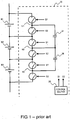
- WO97/44877 describes a switched capacitor system for automatic battery equalization of series coupled batteries.
- the system includes for each pair of batteries a capacitor and a plurality of switching elements.
- Each of the capacitors is switched back and forth between a predetermined pair of batteries for the purpose of transferring charge and equalizing the output voltages of each of the batteries in the pair.
- a major disadvantage of the above system is that the energy charge is always to be distributed through the series connection via adjacent devices. In other words, balancing large numbers of energy storage devices may take a significant amount of time, and this amount of time increases upon extending the number of energy storage devices.
- US 6,404,165 describes a system, wherein a capacitor is connectable in parallel with at least two energy storage devices and wherein voltage monitoring means are used to monitor respective voltages of the energy storage devices and selecting two devices to be balanced to each other.
- a major disadvantage of this method is its inability to efficiently redistribute charge between non-adjacent energy storage devices in a series connection. All such charge redistribution requires multiple, sequential transfer operations making the process slow and lossy.
- Another object of the present invention is to provide a low-cost system and method for balancing a series connection of energy storage devices, which is easily scalable to large numbers of energy storage devices.
- a further object of the present invention is to provide a system and method for balancing a series connection of energy storage devices, which is easily scalable to different types of energy storage devices.
- the invention meets the above objects by providing a system and method wherein an intermediate storage element is coupled between a pair of non-adjacent sections of one or a number of adjacent energy storage devices and wherein sequentially is switched between coupling the more positive terminals (A) of the pair of non-adjacent sections to each other via said intermediate storage element and coupling the more negative terminals (B) to each other via said intermediate storage element.
- the invention relates to a system according to claim 1 and a method according to claim 10.
- the invention is directed to a system for balancing a series connection of energy storage devices comprising:
- the invention is directed to an assembly comprising a series connection of energy storage devices and such balancing system.
- the invention is directed to a method for balancing a series connection of energy storage devices comprising the steps of:
- the invention is also directed to the use of the above system or method for balancing a series connection of electric double-layer capacitors, lithium capacitors, electrochemical battery devices and battery packs, and lithium battery devices like lithium-polymer and lithium-ion battery devices.
- the present invention is based on intermediate energy storage regulation, because this approach offers the best sizing possibilities, interference characteristics and cost-effectiveness with commercially readily available low-cost components for circuit design and regulation of the balancing system.
- a system for balancing a series connection of energy storage devices comprising:
- terminal (A) and terminal (B) are to be understood as respectively the more positive terminal at one end and the more negative terminal at the other end of each section of one or a number of adjacent energy storage devices.
- Another advantage is that such system performs with improved efficiency and requires less time to achieve balancing, even upon extending the series connection to large numbers of energy storage devices or in case of heavy-duty applications requiring repeated energy delivery and storage in rapid succession.
- a balancing system and method according to the invention is able to convey electrical energy between non-adjacent energy storage devices or groups of non-adjacent energy storage devices, and as the speed of energy charge transfer is proportional to the electric potential difference between those energy storage devices or groups, the use of such system results in a generally faster charge redistribution in the series connection of energy storage devices than can be attained with systems allowing only charge to be transferred between adjacent energy storage devices or groups of energy storage devices.
- Another advantage of such system is that manufacturing cost and complexity is minimal while easily scalable to large numbers of energy storage devices and different types of energy storage devices.
- an energy storage device may be any device adapted to store electrical charge, for example electric double-layer capacitors (EDLCs or so-called ultracapacitors or supercaps), lithium capacitors, electrochemical battery devices and battery packs, and lithium battery devices like lithium-polymer and lithium-ion battery devices.
- EDLCs electric double-layer capacitors
- ultracapacitors or supercaps lithium capacitors
- electrochemical battery devices and battery packs lithium battery devices like lithium-polymer and lithium-ion battery devices.
- said non-adjacent sections of a one or a number of adjacent energy storage devices may comprise one or an equal number of nominally equally sized energy storage devices.
- nominally equally sized means that an acceptable deviation between the characteristics of the energy storage devices may be allowed.
- a system for balancing a series connection of energy storage devices comprising a plurality of a pair of non-adjacent sections of one or a number of adjacent energy storage devices and a plurality of respective intermediate storage elements.
- the plurality of respective intermediate storage elements may constitute one or a plurality of serial strings (e).
- the manufacturing of the strings and consequently of the complete system may be significantly simplified.
- two or more pairs of non-adjacent sections of a one or a number of adjacent energy storage devices may comprise overlapping energy storage devices.
- the switching means may concurrently couple all terminals (A) and concurrently couple all terminals (B) with a number of intermediate storage elements equal to the number of respective coupled terminals minus one.
- the intermediate storage element may be any electrical component adapted to intermediately store electrical charge between being coupled to terminals (A) and being coupled to terminals (B), for example capacitors, inductors and transformers.
- the intermediate storage element may be a capacitor.
- the efficiency and reliability of the balancing system may be highly improved due to efficient charge transportation.
- the capacitor used as intermediate storage element may have any capacitance, but preferably between 1 nanofarad and 1 millifarad, more preferably between 10 nanofarad and 100 microfarad, and most preferably around 10 microfarad.
- the applied capacitors may be low-cost components defined for low voltage, usually in the order of maximum energy storage device voltages.
- the switching means may comprise any electrical component adapted to obtain sequential coupling of the intermediate storage element to terminals (A) and to terminals (B).
- the switching means may comprise a Field Effect Transistor (FET) to couple each energy storage device via terminal (A) to an intermediate storage device and a FET to couple each energy storage device via terminal (B) to an intermediate storage device.
- FET Field Effect Transistor
- the above FETs may be replaced by a combination of a diode and a FET.
- the switching means may comprise an alternating configuration of p-channel Metal Oxide Silicon Field Effect Transistors (MOSFETs) and n-channel MOSFETs.
- MOSFETs Metal Oxide Silicon Field Effect Transistors
- the positive and negative electrodes of the intermediate storage element are connected to the drain electrodes of two p-channel MOSFETs, their source electrodes being connected to the terminals (A) of the respective non-adjacent sections of one or a group of energy storage devices, and the positive and negative electrodes of the intermediate storage device are connected to the drain electrodes of two n-channel MOSFETs, their source electrodes being connected to the terminals (B) of the respective sections.
- the electric potentials of the terminals (A) are generally higher than the potentials of the respective terminals (B).
- the gate electrodes of the MOSFETs are connected using a resistance to their respective source terminals (A) and capacitively coupled to a control signal source.
- the gate terminal itself may function as a control signal source for other MOSFETs as well.
- the positive and negative electrodes of the intermediate storage element are connected to the source electrodes of two n-channel MOSFETs, their drain electrodes being connected to the terminals (A) of the respective non-adjacent sections of one or a group of energy storage devices, and the positive and negative electrodes of the intermediate storage device are connected to the source electrodes of two p-channel MOSFETs, their drain electrodes being connected to the terminals (B) of the respective sections.
- the electric potentials of the terminals (A) are generally higher than the potentials of the respective terminals (B).
- the gate electrodes of the MOSFETs are connected using a resistance to their respective source terminals and are capacitively coupled to a control signal source. The gate terminal itself may function as a control signal source for other MOSFETs as well.
- the switching means may also comprise a multiplexer system.
- a system in accordance with the present invention may comprise a clock generating a control signal, or a plurality of control signals in case of a plurality of strings, for controlling the switching means.
- the balancing operation may be fully regulated by modifying the waveform, phase, frequency, duty cycle, amplitude, and/or slew rate of the control signal(s) and can be activated arid deactivated at any time.
- Individual energy storage devices and/or groups of energy storage devices may be brought towards a desired charge or energy levels by introducing additional or external energy source(s) allowing balancing over a larger dynamic range of the individual energy storage device voltages.
- the present invention provides an assembly comprising a series connection of energy storage devices and balancing system in accordance with the embodiments as described above.
- a first advantage of such method is that balancing becomes less time consuming due to improved efficiency of charge transfer through the series section, particularly upon extending the series connection to large numbers of energy storage devices.
- Another advantage of a method in accordance with the present invention is that large numbers of energy storage devices in a serial connection may be balanced concurrently.
- a plurality of pairs of non-adjacent sections of one or a number of adjacent energy storage devices may be selected and the terminals of each pair may be coupled via respective intermediate storage elements, said respective intermediate storage elements constituting one or multiple serial strings.
- the step of selecting may be performed such that two or more pairs comprise overlapping energy storage devices.
- each non-adjacent section of one or a number of adjacent energy storage devices may be selected such that it consists of one energy storage device, wherein said respective intermediate storage elements may constitute three serial strings, wherein pairs of said sections corresponding to the first and second of said serial strings may not comprise overlapping storage devices, and wherein at least one pair corresponding to the third of said serial strings may comprise a storage device overlapping with a storage device of a pair corresponding to the first string, and a storage device overlapping with a storage device of a pair corresponding to the second string.
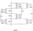
- FIG 5 A balancing system in accordance with the present invention and adapted to perform the above method is illustrated schematically in FIG 5 , wherein four electric energy storage elements (a1, a2, a3, a4) are equalized using three charge redistribution stages. These three stages are controlled, respectively by signals (R1..2), (S1..2) and (T1..2), which do not need to have a relationship between each other and can be configured independently to ensure efficient energy transfer and balancing without unwanted effects.
- Such system is designed for balancing a series connection of energy storage devices at the individual energy storage device level, wherein each section consists of one energy storage device, wherein said respective intermediate storage elements constitute three serial strings, wherein pairs corresponding to the first and second of said serial strings do not comprise overlapping storage devices, and wherein at least one pair corresponding to the third of said serial strings comprise a storage device overlapping with a storage device of a pair corresponding to the first string, and a storage device overlapping with a storage device of a pair corresponding to the second string.
- FIG 6 A detailed example of a balancing system in accordance with the present invention and adapted to perform the above method is illustrated in FIG 6 .
- a method in accordance with the present invention may be used for balancing a series connection of electric double-layer capacitors, lithium capacitors, electrochemical battery devices and battery packs, and lithium battery devices like lithium-polymer and lithium-ion battery devices.
Landscapes
- Engineering & Computer Science (AREA)
- Power Engineering (AREA)
- Charge And Discharge Circuits For Batteries Or The Like (AREA)
- Secondary Cells (AREA)
- Battery Mounting, Suspending (AREA)
Claims (17)
- Système pour équilibrer une connexion en série de dispositifs de stockage d'énergie, comprenant :a. un élément de stockage intermédiaire (b) couplé entre une paire de sections non adjacentes (d) d'un ou d'un certain nombre de dispositifs de stockage d'énergie adjacents (a1, a2, a3) d'une connexion en série de dispositifs de stockage d'énergie, lesdites sections comportant chacune une borne plus positive (A) à une extrémité et une borne plus négative (B) à son autre extrémité ;b. et un moyen de commutation (c) commutant successivement entre le couplage des bornes plus positives (A) les unes aux autres par l'intermédiaire dudit élément de stockage intermédiaire, et le couplage des bornes plus négatives (B) les unes aux autres par l'intermédiaire dudit élément de stockage intermédiaire ;caractérisé en ce que le moyen de commutation découple les bornes plus positives (A) de la paire de sections non adjacentes lors d'un couplage des bornes plus négatives (B) de la paire de sections non adjacentes.
- Système pour équilibrer une connexion en série de dispositifs de stockage d'énergie selon la revendication 1, dans lequel lesdites sections comprennent un ou un nombre égal de dispositifs de stockage d'énergie dimensionnés théoriquement de manière égale.
- Système pour équilibrer une connexion en série de dispositifs de stockage d'énergie selon la revendication 1 à 2, comprenant une pluralité desdites paires et une pluralité d'éléments de stockage intermédiaires respectifs.
- Système pour équilibrer une connexion en série de dispositifs de stockage d'énergie selon la revendication 3, dans lequel la pluralité d'éléments de stockage intermédiaires respectifs constitue une ou une pluralité de chaînes en série.
- Système pour équilibrer une connexion en série de dispositifs de stockage d'énergie selon les revendications 3 à 4, dans lequel deux paires ou plus comprennent des dispositifs de stockage d'énergie se chevauchant.
- Système pour équilibrer une connexion en série de dispositifs de stockage d'énergie selon les revendications 3 à 5, dans lequel le moyen de commutation couple simultanément toutes les bornes (A) et couple simultanément toutes les bornes (B) avec un nombre d'éléments de stockage intermédiaires égal au nombre de bornes couplées respectives moins un.
- Système pour équilibrer une connexion en série de dispositifs de stockage d'énergie selon l'une quelconque des revendications précédentes, dans lequel ledit élément de stockage intermédiaire est un condensateur.
- Système pour équilibrer une connexion en série de dispositifs de stockage d'énergie selon l'une quelconque des revendications précédentes, dans lequel le moyen de commutation comprend une configuration en alternance de transistors MOS de canal p et de transistors MOS de canal n.
- Ensemble comprenant une connexion en série de dispositifs de stockage d'énergie et un système selon les revendications 1 à 8.
- Procédé d'équilibrage d'une connexion en série de dispositifs de stockage d'énergie comprenant les étapes consistant à :a. fournir une connexion en série de dispositifs de stockage d'énergie (a1, a2, a3),b. sélectionner parmi ladite connexion en série une paire de sections non adjacentes (d) d'un ou d'un certain nombre de dispositifs de stockage d'énergie adjacents, lesdites sections destinées à être équilibrées les unes par rapport aux autres et comportant chacune une borne plus positive (A) à une extrémité et une borne plus négative (B) à son autre extrémité,c. coupler les bornes plus positives (A) de ladite paire de sections par l'intermédiaire d'un élément de stockage intermédiaire (b),d. coupler les bornes plus négatives (B) de ladite paire de sections non adjacentes par l'intermédiaire dudit élément de stockage intermédiaire,e. répéter successivement les étapes c et d,caractérisé en ce que l'étape d comprend le découplage des bornes plus positives (A) de la paire de sections non adjacentes.
- Procédé d'équilibrage d'une connexion en série de dispositifs de stockage d'énergie selon la revendication 10, dans lequel lesdites sections comprennent un ou un nombre égal de dispositifs de stockage d'énergie dimensionnés théoriquement de manière égale.
- Procédé d'équilibrage d'une connexion en série de dispositifs de stockage d'énergie selon les revendications 10 ou 11, dans lequel une pluralité desdites paires est sélectionnée, dans lequel les bornes de chaque paire sont couplées par l'intermédiaire d'éléments de stockage intermédiaires respectifs, lesdits éléments de stockage intermédiaires respectifs constituant une ou plusieurs chaînes en série.
- Procédé d'équilibrage d'une connexion en série de dispositifs de stockage d'énergie selon la revendication 12, dans lequel le moyen de commutation correspondant à plusieurs chaînes en série est commandé ou par un ou par plusieurs signaux de commande indépendants.
- Procédé d'équilibrage d'une connexion en série de dispositifs de stockage d'énergie selon les revendications 12 ou 13, dans lequel l'étape de sélection est effectuée de telle sorte que deux paires ou plus comprennent des dispositifs de stockage d'énergie se chevauchant.
- Procédé d'équilibrage d'une connexion en série de dispositifs de stockage d'énergie selon la revendication 14, dans lequel chaque section est constituée d'un dispositif de stockage d'énergie, dans lequel lesdits éléments de stockage intermédiaires respectifs constituent trois chaînes en série, dans lequel des paires correspondant aux première et deuxième desdites chaînes en série ne comprennent pas de dispositifs de stockage se chevauchant, et dans lequel au moins une paire correspondant à la troisième desdites chaînes en série comprend un dispositif de stockage chevauchant un dispositif de stockage d'une paire correspondant à la première chaîne, et un dispositif de stockage chevauchant un dispositif de stockage d'une paire correspondant à la deuxième chaîne.
- Procédé d'équilibrage d'une connexion en série de dispositifs de stockage d'énergie selon la revendication 15, dans lequel le moyen de commutation correspondant à chacune des trois chaînes en série est commandé par des signaux de commande respectifs (R1..2), (S1..2) et (T1..2) .
- Utilisation d'un procédé selon les revendications 10 à 16 pour équilibrer une connexion en série de condensateurs électriques à double couche, des condensateurs au lithium, des dispositifs de batterie et blocs de batterie électrochimiques, et des dispositifs de batterie au lithium de type dispositifs de batterie lithium-polymère et lithium-ion.
Priority Applications (1)
| Application Number | Priority Date | Filing Date | Title |
|---|---|---|---|
| EP10766282.7A EP2491633B1 (fr) | 2009-10-19 | 2010-10-19 | Système et procédé pour l'équilibrage des dispositifs de stockage d'énergie |
Applications Claiming Priority (3)
| Application Number | Priority Date | Filing Date | Title |
|---|---|---|---|
| EP20090173418 EP2312724A1 (fr) | 2009-10-19 | 2009-10-19 | Système et procédé pour l'équilibrage des dispositifs de stockage d'énergie |
| PCT/EP2010/065705 WO2011048087A1 (fr) | 2009-10-19 | 2010-10-19 | Système et procédé d'équilibrage de dispositifs de stockage d'énergie |
| EP10766282.7A EP2491633B1 (fr) | 2009-10-19 | 2010-10-19 | Système et procédé pour l'équilibrage des dispositifs de stockage d'énergie |
Publications (2)
| Publication Number | Publication Date |
|---|---|
| EP2491633A1 EP2491633A1 (fr) | 2012-08-29 |
| EP2491633B1 true EP2491633B1 (fr) | 2017-01-04 |
Family
ID=42112238
Family Applications (2)
| Application Number | Title | Priority Date | Filing Date |
|---|---|---|---|
| EP20090173418 Ceased EP2312724A1 (fr) | 2009-10-19 | 2009-10-19 | Système et procédé pour l'équilibrage des dispositifs de stockage d'énergie |
| EP10766282.7A Revoked EP2491633B1 (fr) | 2009-10-19 | 2010-10-19 | Système et procédé pour l'équilibrage des dispositifs de stockage d'énergie |
Family Applications Before (1)
| Application Number | Title | Priority Date | Filing Date |
|---|---|---|---|
| EP20090173418 Ceased EP2312724A1 (fr) | 2009-10-19 | 2009-10-19 | Système et procédé pour l'équilibrage des dispositifs de stockage d'énergie |
Country Status (7)
| Country | Link |
|---|---|
| US (1) | US9647467B2 (fr) |
| EP (2) | EP2312724A1 (fr) |
| JP (1) | JP2013509142A (fr) |
| CN (1) | CN102577013A (fr) |
| BR (1) | BR112012009027A2 (fr) |
| RU (1) | RU2012118593A (fr) |
| WO (1) | WO2011048087A1 (fr) |
Families Citing this family (6)
| Publication number | Priority date | Publication date | Assignee | Title |
|---|---|---|---|---|
| CN103931076A (zh) * | 2011-09-02 | 2014-07-16 | 波士顿电力公司 | 用于平衡电池中的单元的方法 |
| FR3001089B1 (fr) * | 2013-01-11 | 2016-09-09 | Enerstone | Equilibrage de charge dans une batterie electrique |
| TWI558064B (zh) * | 2015-07-31 | 2016-11-11 | 宏碁股份有限公司 | 電池平衡裝置及其電池平衡方法 |
| WO2018134827A1 (fr) * | 2017-01-23 | 2018-07-26 | B.G. Negev Technologies And Applications Ltd., At Ben-Gurion University | Système d'équilibrage d'une série de cellules |
| US11545841B2 (en) * | 2019-11-18 | 2023-01-03 | Semiconductor Components Industries, Llc | Methods and apparatus for autonomous balancing and communication in a battery system |
| CN111490572B (zh) * | 2020-04-22 | 2021-09-28 | 杭州元色科技有限公司 | 采用倍压开关储能元件的均衡装置、方法及电池管理系统 |
Citations (11)
| Publication number | Priority date | Publication date | Assignee | Title |
|---|---|---|---|---|
| WO1997044877A1 (fr) | 1996-05-20 | 1997-11-27 | The Board Of Trustees Of The University Of Illinois | Systeme de condensateur commute pour egalisation automatique de batteries |
| US6121751A (en) | 1999-03-11 | 2000-09-19 | Lockheed Martin Corporation | Battery charger for charging a stack of multiple lithium ion battery cells |
| US6140800A (en) | 1999-05-27 | 2000-10-31 | Peterson; William Anders | Autonomous battery equalization circuit |
| US6404165B1 (en) | 1997-09-29 | 2002-06-11 | Mitsubishi Jidosha Kogyo | Electricity accumulator |
| US20040212346A1 (en) | 2003-04-25 | 2004-10-28 | Maxwell Technologies, Inc. | Charge balancing circuit |
| US20040246635A1 (en) | 2001-10-01 | 2004-12-09 | Koichi Morita | Voltage balance circuit, voltage detective circuit, voltage balancing method, and voltage detecting method |
| US6841971B1 (en) | 2002-05-29 | 2005-01-11 | Alpha Technologies, Inc. | Charge balancing systems and methods |
| US20050077879A1 (en) | 2003-10-14 | 2005-04-14 | Near Timothy Paul | Energy transfer device for series connected energy source and storage devices |
| US20050269988A1 (en) | 2004-06-04 | 2005-12-08 | Maxwell Technologies, Inc. | Voltage balancing circuit for multi-cell modules |
| WO2007026019A1 (fr) | 2005-09-02 | 2007-03-08 | Vdo Automotive Ag | Dispositif et procede d'equilibrage de charge entre les cellules individuelles d'un condensateur a double couche |
| US20090140694A1 (en) | 2007-11-29 | 2009-06-04 | James Jin Xiong Zeng | Sequencing switched single capacitor for automatic equalization of batteries connected in series |
Family Cites Families (42)
| Publication number | Priority date | Publication date | Assignee | Title |
|---|---|---|---|---|
| DE3940929C1 (fr) | 1989-12-12 | 1991-05-08 | Fraunhofer-Gesellschaft Zur Foerderung Der Angewandten Forschung Ev, 8000 Muenchen, De | |
| DE4427077C1 (de) * | 1994-07-30 | 1996-03-21 | Fraunhofer Ges Forschung | Vorrichtung zum Ladungsaustausch zwischen einer Vielzahl von in Reine geschalteten Energiespeichern oder -wandlern |
| CA2157814A1 (fr) | 1994-09-09 | 1996-03-10 | David R. Pacholok | Egalisation de la charge des piles ou des batteries montees en serie |
| JP3099181B2 (ja) * | 1996-09-10 | 2000-10-16 | 本田技研工業株式会社 | 蓄電器の電圧制御装置 |
| WO1998015047A1 (fr) | 1996-10-03 | 1998-04-09 | Mitsubishi Jidosha Kogyo Kabushiki Kaisha | Dispositif de stockage d'electricite |
| DE19708842A1 (de) | 1997-03-05 | 1998-09-10 | Hans Prof Dr Ing Kahlen | Einrichtung für den Ladeausgleich elektrisch in Reihe geschalteter Elemente |
| US6031355A (en) * | 1997-08-16 | 2000-02-29 | Rich; Joe G. | Circuit utilizing current flowing from a high-potential battery bank to a low-potential battery bank |
| US6064178A (en) | 1998-05-07 | 2000-05-16 | Ford Motor Company | Battery charge balancing system having parallel switched energy storage elements |
| TW472426B (en) | 1998-10-06 | 2002-01-11 | Hitachi Ltd | Battery apparatus and control system therefor |
| US6140799A (en) * | 1999-06-29 | 2000-10-31 | Thomasson; Mark J. | Switched battery-bank assembly for providing incremental voltage control |
| JP2001086656A (ja) | 1999-07-09 | 2001-03-30 | Fujitsu Ltd | バッテリ監視装置 |
| JP3280642B2 (ja) | 1999-09-08 | 2002-05-13 | 長野日本無線株式会社 | 蓄電モジュール |
| FI117259B (fi) | 1999-09-22 | 2006-08-15 | Abb Oy | Välipiirikondensaattoreiden jännitteen tasaus |
| US6642692B2 (en) | 2000-06-23 | 2003-11-04 | Honda Giken Kogyo Kabushiki Kaisha | Charge equalizing device for power storage unit |
| DE10101542A1 (de) | 2000-09-25 | 2002-04-11 | Amita Technologies Inc Ltd | Vorrichtung zum Spannungsabgleich an einer in Reihe geschalteten Akkumulatoranordnung und Verfahren dafür |
| US6281662B1 (en) * | 2000-10-18 | 2001-08-28 | Ford Global Technologies, Inc. | Battery charging DC to DC converter |
| JP3364836B2 (ja) | 2000-10-19 | 2003-01-08 | 富士重工業株式会社 | 電圧イコライザ装置およびその方法 |
| JP3791767B2 (ja) * | 2001-03-27 | 2006-06-28 | 株式会社デンソー | フライングキャパシタ式電圧検出回路 |
| US7615966B2 (en) * | 2001-05-25 | 2009-11-10 | Texas Instruments Northern Virginia Incorporated | Method and apparatus for managing energy in plural energy storage units |
| DE10150376A1 (de) * | 2001-10-11 | 2003-04-17 | Bosch Gmbh Robert | Vorrichtung zum Ausgleich des Ladezustands von in Reihe geschalteten Akkumulatoren |
| US6624612B1 (en) | 2001-10-30 | 2003-09-23 | Symbol Technologies, Inc. | System and method to facilitate voltage balancing in a multi-cell battery |
| US6983212B2 (en) | 2001-11-27 | 2006-01-03 | American Power Conversion Corporation | Battery management system and method |
| DE10247112B3 (de) | 2002-10-09 | 2004-08-26 | Siemens Ag | Verfahren und Vorrichtung zum Einschalten eines zwischen kapazitiven Elementen angeordneten Leistungsschalters |
| US7245108B2 (en) | 2002-11-25 | 2007-07-17 | Tiax Llc | System and method for balancing state of charge among series-connected electrical energy storage units |
| TW571452B (en) | 2002-12-13 | 2004-01-11 | Quanta Comp Inc | Charging-type electrical potential balance device |
| JP4131394B2 (ja) | 2003-02-19 | 2008-08-13 | 株式会社デンソー | 組電池の電圧検出装置 |
| JP2004336919A (ja) | 2003-05-09 | 2004-11-25 | Ricoh Co Ltd | キャパシタ充電回路およびそれに用いる半導体装置 |
| DE102004005136B4 (de) | 2004-02-02 | 2008-05-08 | Siemens Ag | Vorrichtung und Verfahren zum Ladungsausgleich der in Reihe geschalteten Kondensatoren eines Doppelschichtkondensators |
| US7679369B2 (en) | 2006-10-06 | 2010-03-16 | Enerdel, Inc. | System and method to measure series-connected cell voltages using a flying capacitor |
| DE102007023023A1 (de) | 2007-05-16 | 2008-11-27 | Siemens Ag | Schaltungsanordnung und Verfahren zum Betreiben einer Energiespeicheranordnung |
| JP2009081949A (ja) | 2007-09-26 | 2009-04-16 | Toshiba Corp | 組電池の保護装置及びこれを含む組電池システム |
| KR101220339B1 (ko) * | 2007-10-16 | 2013-01-09 | 한국과학기술원 | 직렬연결 배터리 스트링을 위한 자동 전하 균일 방법 및장치 |
| KR101076786B1 (ko) * | 2009-01-30 | 2011-10-25 | 한국과학기술원 | 직렬연결 배터리 스트링을 위한 지능제어 전하균일 장치 및방법 |
| US8570047B1 (en) * | 2009-02-12 | 2013-10-29 | The United States Of America As Represented By The Administrator Of The National Aeronautics And Space Administration | Battery fault detection with saturating transformers |
| US8519670B2 (en) * | 2009-03-23 | 2013-08-27 | Motiv Power Systems, Inc. | System and method for balancing charge within a battery pack |
| US20130002201A1 (en) * | 2009-12-09 | 2013-01-03 | Panacis Inc. | System and method of integrated battery charging and balancing |
| JP2012249369A (ja) * | 2011-05-26 | 2012-12-13 | Toyota Industries Corp | 二次電池電力供給起動回路及びセルバランス装置 |
| JP2012253951A (ja) * | 2011-06-03 | 2012-12-20 | Sony Corp | 電源供給装置、充電方法、充電池モジュール、及び充電装置 |
| US20140042815A1 (en) * | 2012-06-10 | 2014-02-13 | The Regents of the University of Colorado, A Body Corporate | Balancing, filtering and/or controlling series-connected cells |
| TWI560971B (en) * | 2012-07-13 | 2016-12-01 | Fu Sheng Tsai | Balancing circuit for balancing battery units |
| US9362772B2 (en) * | 2012-08-14 | 2016-06-07 | Texas Instruments Incorporated | System and method for balancing voltages |
| US9203246B2 (en) * | 2013-05-16 | 2015-12-01 | Postech Academy-Industry Foundation | Balancing control circuit for battery cell module using LC series resonant circuit |
-
2009
- 2009-10-19 EP EP20090173418 patent/EP2312724A1/fr not_active Ceased
-
2010
- 2010-10-19 RU RU2012118593/07A patent/RU2012118593A/ru not_active Application Discontinuation
- 2010-10-19 WO PCT/EP2010/065705 patent/WO2011048087A1/fr not_active Ceased
- 2010-10-19 JP JP2012533658A patent/JP2013509142A/ja active Pending
- 2010-10-19 CN CN2010800468469A patent/CN102577013A/zh active Pending
- 2010-10-19 US US13/502,256 patent/US9647467B2/en not_active Expired - Fee Related
- 2010-10-19 EP EP10766282.7A patent/EP2491633B1/fr not_active Revoked
- 2010-10-19 BR BR112012009027-5A patent/BR112012009027A2/pt not_active IP Right Cessation
Patent Citations (11)
| Publication number | Priority date | Publication date | Assignee | Title |
|---|---|---|---|---|
| WO1997044877A1 (fr) | 1996-05-20 | 1997-11-27 | The Board Of Trustees Of The University Of Illinois | Systeme de condensateur commute pour egalisation automatique de batteries |
| US6404165B1 (en) | 1997-09-29 | 2002-06-11 | Mitsubishi Jidosha Kogyo | Electricity accumulator |
| US6121751A (en) | 1999-03-11 | 2000-09-19 | Lockheed Martin Corporation | Battery charger for charging a stack of multiple lithium ion battery cells |
| US6140800A (en) | 1999-05-27 | 2000-10-31 | Peterson; William Anders | Autonomous battery equalization circuit |
| US20040246635A1 (en) | 2001-10-01 | 2004-12-09 | Koichi Morita | Voltage balance circuit, voltage detective circuit, voltage balancing method, and voltage detecting method |
| US6841971B1 (en) | 2002-05-29 | 2005-01-11 | Alpha Technologies, Inc. | Charge balancing systems and methods |
| US20040212346A1 (en) | 2003-04-25 | 2004-10-28 | Maxwell Technologies, Inc. | Charge balancing circuit |
| US20050077879A1 (en) | 2003-10-14 | 2005-04-14 | Near Timothy Paul | Energy transfer device for series connected energy source and storage devices |
| US20050269988A1 (en) | 2004-06-04 | 2005-12-08 | Maxwell Technologies, Inc. | Voltage balancing circuit for multi-cell modules |
| WO2007026019A1 (fr) | 2005-09-02 | 2007-03-08 | Vdo Automotive Ag | Dispositif et procede d'equilibrage de charge entre les cellules individuelles d'un condensateur a double couche |
| US20090140694A1 (en) | 2007-11-29 | 2009-06-04 | James Jin Xiong Zeng | Sequencing switched single capacitor for automatic equalization of batteries connected in series |
Also Published As
| Publication number | Publication date |
|---|---|
| CN102577013A (zh) | 2012-07-11 |
| EP2491633A1 (fr) | 2012-08-29 |
| RU2012118593A (ru) | 2013-11-27 |
| JP2013509142A (ja) | 2013-03-07 |
| US9647467B2 (en) | 2017-05-09 |
| BR112012009027A2 (pt) | 2019-09-24 |
| EP2312724A1 (fr) | 2011-04-20 |
| WO2011048087A1 (fr) | 2011-04-28 |
| US20120235494A1 (en) | 2012-09-20 |
Similar Documents
| Publication | Publication Date | Title |
|---|---|---|
| Singirikonda et al. | Active cell voltage balancing of Electric vehicle batteries by using an optimized switched capacitor strategy | |
| EP2491633B1 (fr) | Système et procédé pour l'équilibrage des dispositifs de stockage d'énergie | |
| EP2132855B1 (fr) | Surveillance de cellules dans un système de stockage d'énergie | |
| US9203121B2 (en) | Inductor-based active balancing for batteries and other power supplies | |
| US8436582B2 (en) | Battery cell equalizer system | |
| JP5641781B2 (ja) | セル均等化充電システム及び方法 | |
| CN101849340B (zh) | 集成有电压传感器和充电均衡器的电池管理系统 | |
| CN102195316B (zh) | 电荷存储元件的均衡电路 | |
| JP5502918B2 (ja) | 組電池の充放電装置 | |
| KR101619268B1 (ko) | 배터리셀의 밸런싱 방법 | |
| US20140349146A1 (en) | Battery having a plurality of accumulator cells and method for operating same | |
| US20080272735A1 (en) | Circuit arrangement and method for transferring electrical charge between accumulator arrangement | |
| CN103931076A (zh) | 用于平衡电池中的单元的方法 | |
| US8837170B2 (en) | Passive resonant bidirectional converter with galvanic barrier | |
| CN102263427A (zh) | 储能器装置 | |
| Daowd et al. | Capacitor based battery balancing system | |
| EP2700141A1 (fr) | Système et procédé d'équilibrage de dispositifs de stockage d'énergie | |
| CN102738853B (zh) | 辅助电池充电装置 | |
| Ekanayake et al. | Active and passive based hybrid cell balancing approach to series connected lithium-ion battery pack | |
| US20100007351A1 (en) | Assembled-battery voltage measuring device and assembled-battery voltage system using it | |
| KR101856037B1 (ko) | 단일 인덕터를 이용한 배터리 모듈 밸런싱 방법 | |
| WO2012143422A1 (fr) | Système et procédé de mesure pour un montage en série de dispositifs de stockage d'énergie | |
| Mizanur et al. | A modularized battery charge equalizer in the application of electric vehicle | |
| CN118713244A (zh) | 双层电容式电池均衡电路及电池组均衡控制方法 | |
| CN107306037A (zh) | 一种电池电压监控电路和方法 |
Legal Events
| Date | Code | Title | Description |
|---|---|---|---|
| PUAI | Public reference made under article 153(3) epc to a published international application that has entered the european phase |
Free format text: ORIGINAL CODE: 0009012 |
|
| 17P | Request for examination filed |
Effective date: 20120521 |
|
| AK | Designated contracting states |
Kind code of ref document: A1 Designated state(s): AL AT BE BG CH CY CZ DE DK EE ES FI FR GB GR HR HU IE IS IT LI LT LU LV MC MK MT NL NO PL PT RO RS SE SI SK SM TR |
|
| DAX | Request for extension of the european patent (deleted) | ||
| 17Q | First examination report despatched |
Effective date: 20130523 |
|
| GRAP | Despatch of communication of intention to grant a patent |
Free format text: ORIGINAL CODE: EPIDOSNIGR1 |
|
| STAA | Information on the status of an ep patent application or granted ep patent |
Free format text: STATUS: GRANT OF PATENT IS INTENDED |
|
| GRAS | Grant fee paid |
Free format text: ORIGINAL CODE: EPIDOSNIGR3 |
|
| INTG | Intention to grant announced |
Effective date: 20161107 |
|
| GRAA | (expected) grant |
Free format text: ORIGINAL CODE: 0009210 |
|
| STAA | Information on the status of an ep patent application or granted ep patent |
Free format text: STATUS: THE PATENT HAS BEEN GRANTED |
|
| RIN1 | Information on inventor provided before grant (corrected) |
Inventor name: VIDAEL, RUDOLF Inventor name: VERHAEVEN, ERIC Inventor name: VAN DEN KEYBUS, JEROEN Inventor name: COOSEMANS, JOHAN |
|
| AK | Designated contracting states |
Kind code of ref document: B1 Designated state(s): AL AT BE BG CH CY CZ DE DK EE ES FI FR GB GR HR HU IE IS IT LI LT LU LV MC MK MT NL NO PL PT RO RS SE SI SK SM TR |
|
| REG | Reference to a national code |
Ref country code: GB Ref legal event code: FG4D |
|
| REG | Reference to a national code |
Ref country code: CH Ref legal event code: EP |
|
| REG | Reference to a national code |
Ref country code: AT Ref legal event code: REF Ref document number: 860115 Country of ref document: AT Kind code of ref document: T Effective date: 20170115 |
|
| REG | Reference to a national code |
Ref country code: IE Ref legal event code: FG4D |
|
| REG | Reference to a national code |
Ref country code: DE Ref legal event code: R096 Ref document number: 602010039339 Country of ref document: DE |
|
| REG | Reference to a national code |
Ref country code: NL Ref legal event code: FP |
|
| REG | Reference to a national code |
Ref country code: SE Ref legal event code: TRGR |
|
| REG | Reference to a national code |
Ref country code: LT Ref legal event code: MG4D |
|
| REG | Reference to a national code |
Ref country code: AT Ref legal event code: MK05 Ref document number: 860115 Country of ref document: AT Kind code of ref document: T Effective date: 20170104 |
|
| PG25 | Lapsed in a contracting state [announced via postgrant information from national office to epo] |
Ref country code: IS Free format text: LAPSE BECAUSE OF FAILURE TO SUBMIT A TRANSLATION OF THE DESCRIPTION OR TO PAY THE FEE WITHIN THE PRESCRIBED TIME-LIMIT Effective date: 20170504 Ref country code: GR Free format text: LAPSE BECAUSE OF FAILURE TO SUBMIT A TRANSLATION OF THE DESCRIPTION OR TO PAY THE FEE WITHIN THE PRESCRIBED TIME-LIMIT Effective date: 20170405 Ref country code: LT Free format text: LAPSE BECAUSE OF FAILURE TO SUBMIT A TRANSLATION OF THE DESCRIPTION OR TO PAY THE FEE WITHIN THE PRESCRIBED TIME-LIMIT Effective date: 20170104 Ref country code: NO Free format text: LAPSE BECAUSE OF FAILURE TO SUBMIT A TRANSLATION OF THE DESCRIPTION OR TO PAY THE FEE WITHIN THE PRESCRIBED TIME-LIMIT Effective date: 20170404 Ref country code: FI Free format text: LAPSE BECAUSE OF FAILURE TO SUBMIT A TRANSLATION OF THE DESCRIPTION OR TO PAY THE FEE WITHIN THE PRESCRIBED TIME-LIMIT Effective date: 20170104 Ref country code: HR Free format text: LAPSE BECAUSE OF FAILURE TO SUBMIT A TRANSLATION OF THE DESCRIPTION OR TO PAY THE FEE WITHIN THE PRESCRIBED TIME-LIMIT Effective date: 20170104 |
|
| PG25 | Lapsed in a contracting state [announced via postgrant information from national office to epo] |
Ref country code: RS Free format text: LAPSE BECAUSE OF FAILURE TO SUBMIT A TRANSLATION OF THE DESCRIPTION OR TO PAY THE FEE WITHIN THE PRESCRIBED TIME-LIMIT Effective date: 20170104 Ref country code: PT Free format text: LAPSE BECAUSE OF FAILURE TO SUBMIT A TRANSLATION OF THE DESCRIPTION OR TO PAY THE FEE WITHIN THE PRESCRIBED TIME-LIMIT Effective date: 20170504 Ref country code: AT Free format text: LAPSE BECAUSE OF FAILURE TO SUBMIT A TRANSLATION OF THE DESCRIPTION OR TO PAY THE FEE WITHIN THE PRESCRIBED TIME-LIMIT Effective date: 20170104 Ref country code: ES Free format text: LAPSE BECAUSE OF FAILURE TO SUBMIT A TRANSLATION OF THE DESCRIPTION OR TO PAY THE FEE WITHIN THE PRESCRIBED TIME-LIMIT Effective date: 20170104 Ref country code: PL Free format text: LAPSE BECAUSE OF FAILURE TO SUBMIT A TRANSLATION OF THE DESCRIPTION OR TO PAY THE FEE WITHIN THE PRESCRIBED TIME-LIMIT Effective date: 20170104 Ref country code: BG Free format text: LAPSE BECAUSE OF FAILURE TO SUBMIT A TRANSLATION OF THE DESCRIPTION OR TO PAY THE FEE WITHIN THE PRESCRIBED TIME-LIMIT Effective date: 20170404 Ref country code: LV Free format text: LAPSE BECAUSE OF FAILURE TO SUBMIT A TRANSLATION OF THE DESCRIPTION OR TO PAY THE FEE WITHIN THE PRESCRIBED TIME-LIMIT Effective date: 20170104 |
|
| REG | Reference to a national code |
Ref country code: DE Ref legal event code: R026 Ref document number: 602010039339 Country of ref document: DE |
|
| REG | Reference to a national code |
Ref country code: FR Ref legal event code: PLFP Year of fee payment: 8 |
|
| PLBI | Opposition filed |
Free format text: ORIGINAL CODE: 0009260 |
|
| PG25 | Lapsed in a contracting state [announced via postgrant information from national office to epo] |
Ref country code: EE Free format text: LAPSE BECAUSE OF FAILURE TO SUBMIT A TRANSLATION OF THE DESCRIPTION OR TO PAY THE FEE WITHIN THE PRESCRIBED TIME-LIMIT Effective date: 20170104 Ref country code: IT Free format text: LAPSE BECAUSE OF FAILURE TO SUBMIT A TRANSLATION OF THE DESCRIPTION OR TO PAY THE FEE WITHIN THE PRESCRIBED TIME-LIMIT Effective date: 20170104 Ref country code: CZ Free format text: LAPSE BECAUSE OF FAILURE TO SUBMIT A TRANSLATION OF THE DESCRIPTION OR TO PAY THE FEE WITHIN THE PRESCRIBED TIME-LIMIT Effective date: 20170104 Ref country code: SK Free format text: LAPSE BECAUSE OF FAILURE TO SUBMIT A TRANSLATION OF THE DESCRIPTION OR TO PAY THE FEE WITHIN THE PRESCRIBED TIME-LIMIT Effective date: 20170104 Ref country code: RO Free format text: LAPSE BECAUSE OF FAILURE TO SUBMIT A TRANSLATION OF THE DESCRIPTION OR TO PAY THE FEE WITHIN THE PRESCRIBED TIME-LIMIT Effective date: 20170104 |
|
| PLAX | Notice of opposition and request to file observation + time limit sent |
Free format text: ORIGINAL CODE: EPIDOSNOBS2 |
|
| 26 | Opposition filed |
Opponent name: VITO NV Effective date: 20171004 |
|
| PG25 | Lapsed in a contracting state [announced via postgrant information from national office to epo] |
Ref country code: SM Free format text: LAPSE BECAUSE OF FAILURE TO SUBMIT A TRANSLATION OF THE DESCRIPTION OR TO PAY THE FEE WITHIN THE PRESCRIBED TIME-LIMIT Effective date: 20170104 Ref country code: DK Free format text: LAPSE BECAUSE OF FAILURE TO SUBMIT A TRANSLATION OF THE DESCRIPTION OR TO PAY THE FEE WITHIN THE PRESCRIBED TIME-LIMIT Effective date: 20170104 |
|
| PGFP | Annual fee paid to national office [announced via postgrant information from national office to epo] |
Ref country code: LU Payment date: 20171019 Year of fee payment: 8 |
|
| PGFP | Annual fee paid to national office [announced via postgrant information from national office to epo] |
Ref country code: FR Payment date: 20171024 Year of fee payment: 8 Ref country code: DE Payment date: 20171019 Year of fee payment: 8 |
|
| PG25 | Lapsed in a contracting state [announced via postgrant information from national office to epo] |
Ref country code: SI Free format text: LAPSE BECAUSE OF FAILURE TO SUBMIT A TRANSLATION OF THE DESCRIPTION OR TO PAY THE FEE WITHIN THE PRESCRIBED TIME-LIMIT Effective date: 20170104 |
|
| PGFP | Annual fee paid to national office [announced via postgrant information from national office to epo] |
Ref country code: BE Payment date: 20171019 Year of fee payment: 8 Ref country code: SE Payment date: 20171019 Year of fee payment: 8 Ref country code: GB Payment date: 20171019 Year of fee payment: 8 Ref country code: NL Payment date: 20171019 Year of fee payment: 8 |
|
| PG25 | Lapsed in a contracting state [announced via postgrant information from national office to epo] |
Ref country code: MC Free format text: LAPSE BECAUSE OF FAILURE TO SUBMIT A TRANSLATION OF THE DESCRIPTION OR TO PAY THE FEE WITHIN THE PRESCRIBED TIME-LIMIT Effective date: 20170104 |
|
| REG | Reference to a national code |
Ref country code: CH Ref legal event code: PL |
|
| RDAF | Communication despatched that patent is revoked |
Free format text: ORIGINAL CODE: EPIDOSNREV1 |
|
| REG | Reference to a national code |
Ref country code: DE Ref legal event code: R064 Ref document number: 602010039339 Country of ref document: DE Ref country code: DE Ref legal event code: R103 Ref document number: 602010039339 Country of ref document: DE |
|
| REG | Reference to a national code |
Ref country code: IE Ref legal event code: MM4A |
|
| PG25 | Lapsed in a contracting state [announced via postgrant information from national office to epo] |
Ref country code: LI Free format text: LAPSE BECAUSE OF NON-PAYMENT OF DUE FEES Effective date: 20171031 Ref country code: CH Free format text: LAPSE BECAUSE OF NON-PAYMENT OF DUE FEES Effective date: 20171031 |
|
| PG25 | Lapsed in a contracting state [announced via postgrant information from national office to epo] |
Ref country code: MT Free format text: LAPSE BECAUSE OF NON-PAYMENT OF DUE FEES Effective date: 20171019 |
|
| RDAG | Patent revoked |
Free format text: ORIGINAL CODE: 0009271 |
|
| STAA | Information on the status of an ep patent application or granted ep patent |
Free format text: STATUS: PATENT REVOKED |
|
| PG25 | Lapsed in a contracting state [announced via postgrant information from national office to epo] |
Ref country code: IE Free format text: LAPSE BECAUSE OF NON-PAYMENT OF DUE FEES Effective date: 20171019 |
|
| 27W | Patent revoked |
Effective date: 20180713 |
|
| GBPR | Gb: patent revoked under art. 102 of the ep convention designating the uk as contracting state |
Effective date: 20180713 |
|
| REG | Reference to a national code |
Ref country code: SE Ref legal event code: ECNC |
|
| PG25 | Lapsed in a contracting state [announced via postgrant information from national office to epo] |
Ref country code: MK Free format text: LAPSE BECAUSE OF FAILURE TO SUBMIT A TRANSLATION OF THE DESCRIPTION OR TO PAY THE FEE WITHIN THE PRESCRIBED TIME-LIMIT Effective date: 20170104 |
|
| PG25 | Lapsed in a contracting state [announced via postgrant information from national office to epo] |
Ref country code: CY Free format text: LAPSE BECAUSE OF FAILURE TO SUBMIT A TRANSLATION OF THE DESCRIPTION OR TO PAY THE FEE WITHIN THE PRESCRIBED TIME-LIMIT Effective date: 20170104 |
|
| PG25 | Lapsed in a contracting state [announced via postgrant information from national office to epo] |
Ref country code: AL Free format text: LAPSE BECAUSE OF FAILURE TO SUBMIT A TRANSLATION OF THE DESCRIPTION OR TO PAY THE FEE WITHIN THE PRESCRIBED TIME-LIMIT Effective date: 20170104 |
|
| PG25 | Lapsed in a contracting state [announced via postgrant information from national office to epo] |
Ref country code: TR Free format text: LAPSE BECAUSE OF FAILURE TO SUBMIT A TRANSLATION OF THE DESCRIPTION OR TO PAY THE FEE WITHIN THE PRESCRIBED TIME-LIMIT Effective date: 20170104 |