EP2491966B1 - Blutpumpe, insbesondere eine pneumatische ventrikuläre Hilfsvorrichtung - Google Patents
Blutpumpe, insbesondere eine pneumatische ventrikuläre Hilfsvorrichtung Download PDFInfo
- Publication number
- EP2491966B1 EP2491966B1 EP11183484.2A EP11183484A EP2491966B1 EP 2491966 B1 EP2491966 B1 EP 2491966B1 EP 11183484 A EP11183484 A EP 11183484A EP 2491966 B1 EP2491966 B1 EP 2491966B1
- Authority
- EP
- European Patent Office
- Prior art keywords
- connector
- blood
- nut
- pump
- pump according
- Prior art date
- Legal status (The legal status is an assumption and is not a legal conclusion. Google has not performed a legal analysis and makes no representation as to the accuracy of the status listed.)
- Active
Links
Images

Classifications
-
- A—HUMAN NECESSITIES
- A61—MEDICAL OR VETERINARY SCIENCE; HYGIENE
- A61M—DEVICES FOR INTRODUCING MEDIA INTO, OR ONTO, THE BODY; DEVICES FOR TRANSDUCING BODY MEDIA OR FOR TAKING MEDIA FROM THE BODY; DEVICES FOR PRODUCING OR ENDING SLEEP OR STUPOR
- A61M60/00—Blood pumps; Devices for mechanical circulatory actuation; Balloon pumps for circulatory assistance
- A61M60/40—Details relating to driving
- A61M60/424—Details relating to driving for positive displacement blood pumps
- A61M60/427—Details relating to driving for positive displacement blood pumps the force acting on the blood contacting member being hydraulic or pneumatic
-
- A—HUMAN NECESSITIES
- A61—MEDICAL OR VETERINARY SCIENCE; HYGIENE
- A61M—DEVICES FOR INTRODUCING MEDIA INTO, OR ONTO, THE BODY; DEVICES FOR TRANSDUCING BODY MEDIA OR FOR TAKING MEDIA FROM THE BODY; DEVICES FOR PRODUCING OR ENDING SLEEP OR STUPOR
- A61M60/00—Blood pumps; Devices for mechanical circulatory actuation; Balloon pumps for circulatory assistance
- A61M60/10—Location thereof with respect to the patient's body
- A61M60/122—Implantable pumps or pumping devices, i.e. the blood being pumped inside the patient's body
- A61M60/165—Implantable pumps or pumping devices, i.e. the blood being pumped inside the patient's body implantable in, on, or around the heart
- A61M60/178—Implantable pumps or pumping devices, i.e. the blood being pumped inside the patient's body implantable in, on, or around the heart drawing blood from a ventricle and returning the blood to the arterial system via a cannula external to the ventricle, e.g. left or right ventricular assist devices
-
- A—HUMAN NECESSITIES
- A61—MEDICAL OR VETERINARY SCIENCE; HYGIENE
- A61M—DEVICES FOR INTRODUCING MEDIA INTO, OR ONTO, THE BODY; DEVICES FOR TRANSDUCING BODY MEDIA OR FOR TAKING MEDIA FROM THE BODY; DEVICES FOR PRODUCING OR ENDING SLEEP OR STUPOR
- A61M60/00—Blood pumps; Devices for mechanical circulatory actuation; Balloon pumps for circulatory assistance
- A61M60/80—Constructional details other than related to driving
- A61M60/855—Constructional details other than related to driving of implantable pumps or pumping devices
- A61M60/857—Implantable blood tubes
- A61M60/859—Connections therefor
-
- A—HUMAN NECESSITIES
- A61—MEDICAL OR VETERINARY SCIENCE; HYGIENE
- A61M—DEVICES FOR INTRODUCING MEDIA INTO, OR ONTO, THE BODY; DEVICES FOR TRANSDUCING BODY MEDIA OR FOR TAKING MEDIA FROM THE BODY; DEVICES FOR PRODUCING OR ENDING SLEEP OR STUPOR
- A61M60/00—Blood pumps; Devices for mechanical circulatory actuation; Balloon pumps for circulatory assistance
- A61M60/80—Constructional details other than related to driving
- A61M60/855—Constructional details other than related to driving of implantable pumps or pumping devices
- A61M60/89—Valves
Definitions
- the subject of the invention is a blood pump, in particular a pneumatic ventricular assist device.
- the known pneumatic ventricular assist devices are applied to support the hearts of patients with congestive heart failure.
- the known ventricular assist device which is in practice a blood pump, comprises a spherical cap with a blood chamber and an air chamber separated by a membrane. The membrane is mounted around the inside perimeter of the spherical cap.
- the blood chamber of the spherical cap has an inlet channel for blood and an outlet channel for blood, which channels have circular seats for mounting valves regulating the blood flow through the pump.
- external ventricular assist devices mechanical, disc heart valves are applied.
- Connectors used for connecting the pump to cannulas joining the pump to the circulatory system of a patient are fixed to the inlet and outlet channels with first ends thereof.
- the pneumatic part of the spherical cap is connected to a generator making alternate pneumatic wave which stimulates alternate movement of the membrane located between the pneumatic part of the spherical cap and the blood chamber thereof.
- the alternate movement of the membrane results in the blood flowing through the device.
- the diameters of the seats in the inlet channel and the outlet channel are the same or the diameter of the inlet channel is larger than the diameter of the outlet channel.
- the connector along the working length thereof except for the connecting section has an inside channel whose cross-section is partially uniform and partially narrowing towards the second end which is used for connecting with the cannula.
- the example of a pneumatic ventricular assist device is known from the Polish utility model description no. Ru. 63283 ( PL63283 ).
- the invention relates to a blood pump as claimed, in particular a pneumatic ventricular assist device comprising a spherical cap with an air chamber and a blood chamber separated by a membrane mounted around the inside perimeter of the spherical cap.
- the blood chamber of the spherical cap has an inlet channel for blood and an outlet channel for blood which channels have circular seats for mounting valves regulating the blood flow through the pump.
- Connectors used for connecting the pump to the cannulas joining the pump with the circulatory system of a patient are fastened to the inlet channel and the outlet channel with the first ends thereof.
- the essence of the invention is that the diameter of the seat for the valve in the inlet channel is smaller than the diameter of the seat for the valve in the outlet channel, whereas the inside channel of each connector along the full working length thereof is uniformly convergent towards the second end of said connector.
- the ratio of the diameters of the seat in the inlet channel and the seat on the outlet channel is between 0.75 and 0.92, preferably 0.83.
- the connector on the outside surface of the second end thereof provided for connecting to a cannula has an external stop which allows to precisely determine the distance at which the cannula should be mounted on the second end of the connector.
- the connector is connected to the cannula with a two-part nut which may also be fixed on the connector by means of a screw fastening or a form-fitting coupling, which allows for the nut to be fastened to the cannula already mounted on the second end of the connector and significantly facilitates the assembly of the connection.
- the length of the nut is smaller than the distance between the extreme end of a coupling element of the connector assigned to said nut and the second end of the connector, owing to this following appropriate mounting of the cannula on the second end of the connector and appropriate seating of the nut, a protruding part of the second end of the connector is visible through the transparent cannula. It allows to assess the correctness of the fastening of the nut and also allows to observe the area of the inflow and outflow of blood into the inlet connector and from the outlet connector during the operation of the device.
- the blood pump in particular the pneumatic ventricular heart assist device according to the invention as claimed optimises the parameters of blood flow on the inlet and outlet of the device owing to the appropriate differentiation of diameters of the seats for valves in the inlet channel and the outlet channel, which results in the analogical differentiation of the size of the valves mounted in said seats and owing to the new shape of the inside channel of the device connectors. It allows to reduce the areas of stagnation with the speed of blood flow too low to ensure sufficient blood flush and to reduce the areas where the shear stress caused by turbulent flow have a hemolytic influence on blood. As a result a reduced risk of intravascular coagulation or thrombosis in the device was achieved.
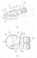
- fig.1 shows a schematic side view of the device
- fig.2 - a schematic top view of the device
- fig. 3 schematically presented seats of the inlet channel and of the outlet channel located next to each other, with the ventricular assist device not shown in the figure
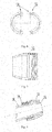
- fig. 4 a schematic longitudinal section of the connector
- fig. 5 a close-up of the side view of the nut mounted on the connector with the shown protruding element of the connector
- fig. 6 - a cross section of the adjacent parts of the two-part nut
- fig. 7 - a longitudinal section of the nut
- fig. 8 - a transverse section of the perspective view of the nut screwed on the second end of the connector.
- a blood pump in the form of a pneumatic heart assist device 1 comprises a spherical cap 2 which has an air chamber 4 and a blood chamber 3 separated by a membrane mounted around the inside perimeter of the spherical cap 2.
- the blood chamber 3 of the spherical cap 2 has an inlet channel 5 for blood and an outlet channel 6 for blood, inside which channels 5, 6 there are circular seats 7, 8 for mounting mechanical valves regulating the flow of blood through the pump.
- To the inlet channel 5 and the outlet channel 6 are mounted connectors 9 with the first ends thereof, used for coupling the pump with cannulas connecting the pump with the circulatory system of a patient.
- the diameter D 1 of the seat 7 for the valve in the inlet channel 5 is smaller than the diameter D2 of the seat 8 for the valve in the outlet channel 6.
- the diameter D1 of the seat 7 is 20mm, whereas the diameter D2 of the seat 8 is 24mm.
- the invention also relates to embodiments where the diameter ratio D1 / D2 is between 0.75 and 0.92. The above difference in the diameters D1 and D2 of the seats 7 and 8 results in different sizes of the mechanical valves mounted in said seats.
- each connector 9 along the full working length thereof, except for the connecting section 10, where the connector 9 is mounted on the outlets of the inlet channel 5 and the outlet channel 6, is uniformly convergent towards the second end of said connector 9.
- the angle of the inside surfaces of the connectors 9 with reference to the connector axis is 4°.
- the invention also relates to embodiments where the angle is smaller than 5°.
- an external stop 11 On the external surface of the connector 9 at the second end thereof used for coupling with the cannula, there is an external stop 11 which allows to precisely determine the distance at which the cannula should be mounted on the second end of the connector 9.
- the connector 9 is coupled with the cannula, not shown in the drawing, by means of a two-part nut 12.
- the nut 12 consists of two elements interconnected by means of a form-fitting guide coupling 13 with longitudinal run with reference to the nut hole axis.
- the coupling of the elements of the nut 12 consists in that both halves are mounted on the cannula already mounted on the connector and connects by means of sliding mutually corresponding form-fitting elements of the guide coupling.
- the nut 12 coupled in this manner is fastened to the connector 9 by means of a screw fastening, which is shown in fig. 8 .
- a fastened screw element comprising, for example, two halfrings on which the nut 12 is screwed on.
- any useful form-fitting coupling could be used.
- the length of the nut 12 is smaller than the distance between the extreme end 14 of a coupling element of the connector 9, in this case a screw fastening corresponding with the nut and the second end of the connector 9.
Landscapes
- Health & Medical Sciences (AREA)
- Heart & Thoracic Surgery (AREA)
- Engineering & Computer Science (AREA)
- Cardiology (AREA)
- Biomedical Technology (AREA)
- Anesthesiology (AREA)
- Mechanical Engineering (AREA)
- Hematology (AREA)
- Life Sciences & Earth Sciences (AREA)
- Animal Behavior & Ethology (AREA)
- General Health & Medical Sciences (AREA)
- Public Health (AREA)
- Veterinary Medicine (AREA)
- External Artificial Organs (AREA)
Claims (9)
- Blutpumpe, insbesondere die pneumatische Herz-Hilfspumpe /1/, ausgerüstet mit der Schale /2/, die die Luftkammer /4/ und die Blutkammer /3/ aufweist, welche mittels am Schalenumfang befestigten Membran voneinander getrennt sind, wobei die Blutkammer /3/ der Schale /2/ mit dem Blut-Einlasskanal /5/ und dem Blut-Auslasskanal /6/ ausgerüstet ist, und die Blut-Kanäle /5, 6/ runde Aufnahmebüchsen /7, 8/ für Aufnahme der Drosselklappen zur Regelung des Blutdurchflusses durch die Blutpumpe aufweisen, und die Anschlusselemente /9/ hingegen, vorgesehen für Anschluss der Blutpumpe an die Kanülen, die die Blutpumpe mit dem Blutkreislauf des Patienten verbinden, sind mit ihren ersten Enden an die Blut-Einlass- und Blut-Auslasskanäle befestigt, gekennzeichnet dadurch, dass der Durchmesser /D1/ der Aufnahmebüchse /7/ für die Drosselklappe im Blut-Einlasskanal /5/ kleiner als der Durchmesser /D2/ der Aufnahmebüchse /8/ für die Drosselklappe im Blut-Auslasskanal /6/ ist, jedoch der innere Kanal jedes Anschlusselements /9/ verjüngt sich gleichmäßig seiner ganzen Arbeitslänge entlang zu dem anderen Ende des gegebenen Anschlusselements /9/ hin.
- Blutpumpe nach Anspruch 1 gekennzeichnet dadurch, dass das Verhältnis der Durchmesser /D1:D2/ der Aufnahmebüchse /7/ des Blut-Einlasskanals /5/ und der Aufnahmebüchse /8/ des Blut-Auslasskanals /6/ im Bereich von 0,75 bis 0,92 beinhaltet ist, und vorzugsweise 0,83 beträgt.
- Blutpumpe nach Anspruch 1 gekennzeichnet dadurch, dass die inneren Oberflächen der Kanäle der Anschlusselemente /9/ zur Achse des Anschlusselements /9/ geneigt sind, und der Neigungswinkel weniger als 5°, und vorzugsweise 4° beträgt.
- Blutpumpe nach Anspruch 1 oder 2 oder 3 gekennzeichnet dadurch, dass das Anschlusselement /9/ mit dem Begrenzer /11/ ausgerüstet ist, der an der Außenseite seines zweiten, zur Verbindung mit der Kanüle bestimmten Ende, lokalisiert ist.
- Blutpumpe nach einem der obigen Ansprüche gekennzeichnet dadurch, dass das Anschlusselement /9/ mit einer Kanüle mittels einer aus zwei Elementen bestehenden Schraubenmutter /12/ verbunden ist.
- Blutpumpe nach Anspruch 5 gekennzeichnet dadurch, dass die Schraubenmutter /12/ mittels Schraubenverbindung an dem Anschlusselement /9/ befestigt ist.
- Blutpumpe nach Anspruch 5 gekennzeichnet dadurch, dass die Schraubenmutter /12/ an dem Anschlusselement /9/ über Formschluss befestigt ist.
- Blutpumpe nach Anspruch 5 oder 6 oder 7 gekennzeichnet dadurch, dass die Länge der Schraubenmutter /12/ kleiner als der Abstand zwischen dem äußersten Endpunkt /14/ des Verbindungteils des Anschlusselements /9/ für diese Schraubenmutter /12/ und dem zweiten Ende des Anschlusselements /9/ ist.
- Blutpumpe nach einem der Ansprüche von 5 bis 8 gekennzeichnet dadurch, dass die beiden Elemente der Schraubenmutter /12/ mittels Führungsformschluss /13/, welcher den Längsverlauf zur Achse der Öffnung der Schraubenmutter /12/ aufweist, miteinander verbunden sind.
Priority Applications (1)
| Application Number | Priority Date | Filing Date | Title |
|---|---|---|---|
| PL11183484T PL2491966T3 (pl) | 2011-02-28 | 2011-09-30 | Pompa krwi, zwłaszcza pneumatyczna komora wspomagania serca |
Applications Claiming Priority (1)
| Application Number | Priority Date | Filing Date | Title |
|---|---|---|---|
| PL394056A PL217321B1 (pl) | 2011-02-28 | 2011-02-28 | Pompa krwi, zwłaszcza pneumatyczna komora wspomagania serca |
Publications (2)
| Publication Number | Publication Date |
|---|---|
| EP2491966A1 EP2491966A1 (de) | 2012-08-29 |
| EP2491966B1 true EP2491966B1 (de) | 2013-12-25 |
Family
ID=45047561
Family Applications (1)
| Application Number | Title | Priority Date | Filing Date |
|---|---|---|---|
| EP11183484.2A Active EP2491966B1 (de) | 2011-02-28 | 2011-09-30 | Blutpumpe, insbesondere eine pneumatische ventrikuläre Hilfsvorrichtung |
Country Status (2)
| Country | Link |
|---|---|
| EP (1) | EP2491966B1 (de) |
| PL (2) | PL217321B1 (de) |
Families Citing this family (6)
| Publication number | Priority date | Publication date | Assignee | Title |
|---|---|---|---|---|
| GB2555435A (en) * | 2016-10-27 | 2018-05-02 | Calon Cardio Tech Ltd | Cardiac pump |
| CN108653840B (zh) * | 2017-03-31 | 2019-08-20 | 广东省心血管病研究所 | 囊状腔肺辅助循环装置 |
| GB2616240B (en) * | 2021-03-17 | 2025-02-26 | 3R Life Sciences Corp | Para-aortic blood pump device |
| US11745004B1 (en) * | 2022-07-15 | 2023-09-05 | Vitalmex Internacional S.A. De C.V. | Ventricular assist devices and methods |
| CN118454101B (zh) * | 2023-02-07 | 2026-03-27 | 深圳核心医疗科技股份有限公司 | 壳体组件及其制造方法和血泵 |
| CN120094093B (zh) * | 2025-04-28 | 2025-07-22 | 脉柯斯医疗科技(绍兴)有限公司 | 一种隔膜泵、心室辅助装置及心室辅助设备 |
Family Cites Families (5)
| Publication number | Priority date | Publication date | Assignee | Title |
|---|---|---|---|---|
| US4167046A (en) * | 1977-12-12 | 1979-09-11 | Andros, Inc. | Blood pumping device |
| US4222127A (en) * | 1978-06-02 | 1980-09-16 | Donachy And Pierce | Blood pump and method of pumping blood |
| DE10119691A1 (de) * | 2001-04-20 | 2002-11-21 | Deutsch Zentr Luft & Raumfahrt | System zum Unterstützen des linken Herzventrikels |
| PL63283Y1 (pl) * | 2004-11-11 | 2007-07-31 | Fundacja Rozwoju Kardiochirurg | Pneumatyczna komora wspomagania serca PL |
| RU63283U1 (ru) | 2006-11-27 | 2007-05-27 | Государственное образовательное учреждение высшего профессионального образования "Курский государственный технический университет" | Модель удержания алмазно-абразивного зерна в органических связках шлифовального инструмента |
-
2011
- 2011-02-28 PL PL394056A patent/PL217321B1/pl unknown
- 2011-09-30 EP EP11183484.2A patent/EP2491966B1/de active Active
- 2011-09-30 PL PL11183484T patent/PL2491966T3/pl unknown
Also Published As
| Publication number | Publication date |
|---|---|
| PL217321B1 (pl) | 2014-07-31 |
| PL394056A1 (pl) | 2012-09-10 |
| PL2491966T3 (pl) | 2014-05-30 |
| EP2491966A1 (de) | 2012-08-29 |
Similar Documents
| Publication | Publication Date | Title |
|---|---|---|
| EP2491966B1 (de) | Blutpumpe, insbesondere eine pneumatische ventrikuläre Hilfsvorrichtung | |
| EP2617443B1 (de) | Druckbetätigte Einzellumen-Blutpumpvorrichtung | |
| US12370297B2 (en) | Devices and methods for extracorporeal conditioning of blood | |
| WO2020016438A1 (de) | Zulaufleitung für eine pumpeneinheit eines herzunterstützungssystems, herzunterstützungssystem und verfahren zum herstellen einer zulaufleitung für eine pumpeneinheit eines herzunterstützungssystems | |
| EP2517739B1 (de) | Blutpumpe, insbesondere eine pneumatische Herzunterstützungsvorrichtung | |
| WO2008144398A3 (en) | Pump module for use in a medical fluid dispensing system | |
| WO2010056323A3 (en) | Modular therapeutic pressure application devices | |
| WO2016005803A3 (en) | Ventricular assist device | |
| EP1681520A3 (de) | Flüssigkeitsarmatur | |
| US5407424A (en) | Angioplasty perfusion pump | |
| EP2592273A3 (de) | Hydraulikpumpenanordnung | |
| WO2006120464A3 (en) | Biomechanical probe | |
| EP2942070B1 (de) | Schlauchleitung für frische und/oder verbrauchte dialysierflüssigkeit | |
| EP2378127A3 (de) | Strömungsführendes Bauteil mit Pumpe und Armatur | |
| CN203556057U (zh) | 一种防回血连接阀 | |
| CN204762588U (zh) | 一种用于农田水利的防倒吸滴灌流量调节阀 | |
| CA2643122A1 (en) | A hydraulic connector and a hydraulic circuit incorporating the connector | |
| EP2336668A3 (de) | Wassererwärmer mit wärmeisolierendem Halter | |
| EP2712636A1 (de) | Herzunterstützungspumpe für Kinder | |
| US8894629B2 (en) | High flow catheter valve | |
| RU2138158C1 (ru) | Устройство для гомогенизации жидкостей | |
| CN222885304U (zh) | 一种流体缓冲装置 | |
| CN208598910U (zh) | 一种输血连接装置 | |
| CN202418731U (zh) | 一种四通隔膜阀 | |
| EP2602390A3 (de) | Duschvorrichtung |
Legal Events
| Date | Code | Title | Description |
|---|---|---|---|
| PUAI | Public reference made under article 153(3) epc to a published international application that has entered the european phase |
Free format text: ORIGINAL CODE: 0009012 |
|
| AK | Designated contracting states |
Kind code of ref document: A1 Designated state(s): AL AT BE BG CH CY CZ DE DK EE ES FI FR GB GR HR HU IE IS IT LI LT LU LV MC MK MT NL NO PL PT RO RS SE SI SK SM TR |
|
| 17P | Request for examination filed |
Effective date: 20130225 |
|
| GRAP | Despatch of communication of intention to grant a patent |
Free format text: ORIGINAL CODE: EPIDOSNIGR1 |
|
| INTG | Intention to grant announced |
Effective date: 20130719 |
|
| GRAS | Grant fee paid |
Free format text: ORIGINAL CODE: EPIDOSNIGR3 |
|
| GRAA | (expected) grant |
Free format text: ORIGINAL CODE: 0009210 |
|
| RAP1 | Party data changed (applicant data changed or rights of an application transferred) |
Owner name: FUNDACJA ROZWOJU KARDIOCHIRURGII IM. PROF. ZBIGNIE |
|
| AK | Designated contracting states |
Kind code of ref document: B1 Designated state(s): AL AT BE BG CH CY CZ DE DK EE ES FI FR GB GR HR HU IE IS IT LI LT LU LV MC MK MT NL NO PL PT RO RS SE SI SK SM TR |
|
| REG | Reference to a national code |
Ref country code: GB Ref legal event code: FG4D |
|
| REG | Reference to a national code |
Ref country code: CH Ref legal event code: EP |
|
| REG | Reference to a national code |
Ref country code: AT Ref legal event code: REF Ref document number: 646222 Country of ref document: AT Kind code of ref document: T Effective date: 20140115 |
|
| REG | Reference to a national code |
Ref country code: IE Ref legal event code: FG4D |
|
| REG | Reference to a national code |
Ref country code: DE Ref legal event code: R096 Ref document number: 602011004330 Country of ref document: DE Effective date: 20140213 |
|
| PG25 | Lapsed in a contracting state [announced via postgrant information from national office to epo] |
Ref country code: NO Free format text: LAPSE BECAUSE OF FAILURE TO SUBMIT A TRANSLATION OF THE DESCRIPTION OR TO PAY THE FEE WITHIN THE PRESCRIBED TIME-LIMIT Effective date: 20140325 Ref country code: FI Free format text: LAPSE BECAUSE OF FAILURE TO SUBMIT A TRANSLATION OF THE DESCRIPTION OR TO PAY THE FEE WITHIN THE PRESCRIBED TIME-LIMIT Effective date: 20131225 Ref country code: HR Free format text: LAPSE BECAUSE OF FAILURE TO SUBMIT A TRANSLATION OF THE DESCRIPTION OR TO PAY THE FEE WITHIN THE PRESCRIBED TIME-LIMIT Effective date: 20131225 Ref country code: SE Free format text: LAPSE BECAUSE OF FAILURE TO SUBMIT A TRANSLATION OF THE DESCRIPTION OR TO PAY THE FEE WITHIN THE PRESCRIBED TIME-LIMIT Effective date: 20131225 Ref country code: LT Free format text: LAPSE BECAUSE OF FAILURE TO SUBMIT A TRANSLATION OF THE DESCRIPTION OR TO PAY THE FEE WITHIN THE PRESCRIBED TIME-LIMIT Effective date: 20131225 |
|
| REG | Reference to a national code |
Ref country code: NL Ref legal event code: VDEP Effective date: 20131225 |
|
| REG | Reference to a national code |
Ref country code: LT Ref legal event code: MG4D |
|
| PG25 | Lapsed in a contracting state [announced via postgrant information from national office to epo] |
Ref country code: RS Free format text: LAPSE BECAUSE OF FAILURE TO SUBMIT A TRANSLATION OF THE DESCRIPTION OR TO PAY THE FEE WITHIN THE PRESCRIBED TIME-LIMIT Effective date: 20131225 Ref country code: LV Free format text: LAPSE BECAUSE OF FAILURE TO SUBMIT A TRANSLATION OF THE DESCRIPTION OR TO PAY THE FEE WITHIN THE PRESCRIBED TIME-LIMIT Effective date: 20131225 |
|
| REG | Reference to a national code |
Ref country code: PL Ref legal event code: T3 |
|
| PG25 | Lapsed in a contracting state [announced via postgrant information from national office to epo] |
Ref country code: EE Free format text: LAPSE BECAUSE OF FAILURE TO SUBMIT A TRANSLATION OF THE DESCRIPTION OR TO PAY THE FEE WITHIN THE PRESCRIBED TIME-LIMIT Effective date: 20131225 Ref country code: IS Free format text: LAPSE BECAUSE OF FAILURE TO SUBMIT A TRANSLATION OF THE DESCRIPTION OR TO PAY THE FEE WITHIN THE PRESCRIBED TIME-LIMIT Effective date: 20140425 Ref country code: BE Free format text: LAPSE BECAUSE OF FAILURE TO SUBMIT A TRANSLATION OF THE DESCRIPTION OR TO PAY THE FEE WITHIN THE PRESCRIBED TIME-LIMIT Effective date: 20131225 |
|
| PG25 | Lapsed in a contracting state [announced via postgrant information from national office to epo] |
Ref country code: RO Free format text: LAPSE BECAUSE OF FAILURE TO SUBMIT A TRANSLATION OF THE DESCRIPTION OR TO PAY THE FEE WITHIN THE PRESCRIBED TIME-LIMIT Effective date: 20131225 Ref country code: CY Free format text: LAPSE BECAUSE OF FAILURE TO SUBMIT A TRANSLATION OF THE DESCRIPTION OR TO PAY THE FEE WITHIN THE PRESCRIBED TIME-LIMIT Effective date: 20131225 Ref country code: NL Free format text: LAPSE BECAUSE OF FAILURE TO SUBMIT A TRANSLATION OF THE DESCRIPTION OR TO PAY THE FEE WITHIN THE PRESCRIBED TIME-LIMIT Effective date: 20131225 Ref country code: PT Free format text: LAPSE BECAUSE OF FAILURE TO SUBMIT A TRANSLATION OF THE DESCRIPTION OR TO PAY THE FEE WITHIN THE PRESCRIBED TIME-LIMIT Effective date: 20140428 Ref country code: SK Free format text: LAPSE BECAUSE OF FAILURE TO SUBMIT A TRANSLATION OF THE DESCRIPTION OR TO PAY THE FEE WITHIN THE PRESCRIBED TIME-LIMIT Effective date: 20131225 Ref country code: ES Free format text: LAPSE BECAUSE OF FAILURE TO SUBMIT A TRANSLATION OF THE DESCRIPTION OR TO PAY THE FEE WITHIN THE PRESCRIBED TIME-LIMIT Effective date: 20131225 Ref country code: CZ Free format text: LAPSE BECAUSE OF FAILURE TO SUBMIT A TRANSLATION OF THE DESCRIPTION OR TO PAY THE FEE WITHIN THE PRESCRIBED TIME-LIMIT Effective date: 20131225 |
|
| REG | Reference to a national code |
Ref country code: DE Ref legal event code: R097 Ref document number: 602011004330 Country of ref document: DE |
|
| PG25 | Lapsed in a contracting state [announced via postgrant information from national office to epo] |
Ref country code: DK Free format text: LAPSE BECAUSE OF FAILURE TO SUBMIT A TRANSLATION OF THE DESCRIPTION OR TO PAY THE FEE WITHIN THE PRESCRIBED TIME-LIMIT Effective date: 20131225 |
|
| PLBE | No opposition filed within time limit |
Free format text: ORIGINAL CODE: 0009261 |
|
| STAA | Information on the status of an ep patent application or granted ep patent |
Free format text: STATUS: NO OPPOSITION FILED WITHIN TIME LIMIT |
|
| 26N | No opposition filed |
Effective date: 20140926 |
|
| REG | Reference to a national code |
Ref country code: DE Ref legal event code: R097 Ref document number: 602011004330 Country of ref document: DE Effective date: 20140926 |
|
| PG25 | Lapsed in a contracting state [announced via postgrant information from national office to epo] |
Ref country code: LU Free format text: LAPSE BECAUSE OF FAILURE TO SUBMIT A TRANSLATION OF THE DESCRIPTION OR TO PAY THE FEE WITHIN THE PRESCRIBED TIME-LIMIT Effective date: 20140930 Ref country code: MC Free format text: LAPSE BECAUSE OF FAILURE TO SUBMIT A TRANSLATION OF THE DESCRIPTION OR TO PAY THE FEE WITHIN THE PRESCRIBED TIME-LIMIT Effective date: 20131225 |
|
| REG | Reference to a national code |
Ref country code: CH Ref legal event code: PL |
|
| PG25 | Lapsed in a contracting state [announced via postgrant information from national office to epo] |
Ref country code: SI Free format text: LAPSE BECAUSE OF FAILURE TO SUBMIT A TRANSLATION OF THE DESCRIPTION OR TO PAY THE FEE WITHIN THE PRESCRIBED TIME-LIMIT Effective date: 20131225 |
|
| REG | Reference to a national code |
Ref country code: IE Ref legal event code: MM4A |
|
| PG25 | Lapsed in a contracting state [announced via postgrant information from national office to epo] |
Ref country code: CH Free format text: LAPSE BECAUSE OF NON-PAYMENT OF DUE FEES Effective date: 20140930 Ref country code: LI Free format text: LAPSE BECAUSE OF NON-PAYMENT OF DUE FEES Effective date: 20140930 |
|
| PG25 | Lapsed in a contracting state [announced via postgrant information from national office to epo] |
Ref country code: IE Free format text: LAPSE BECAUSE OF NON-PAYMENT OF DUE FEES Effective date: 20140930 |
|
| PG25 | Lapsed in a contracting state [announced via postgrant information from national office to epo] |
Ref country code: SM Free format text: LAPSE BECAUSE OF FAILURE TO SUBMIT A TRANSLATION OF THE DESCRIPTION OR TO PAY THE FEE WITHIN THE PRESCRIBED TIME-LIMIT Effective date: 20131225 |
|
| PG25 | Lapsed in a contracting state [announced via postgrant information from national office to epo] |
Ref country code: IT Free format text: LAPSE BECAUSE OF FAILURE TO SUBMIT A TRANSLATION OF THE DESCRIPTION OR TO PAY THE FEE WITHIN THE PRESCRIBED TIME-LIMIT Effective date: 20131225 Ref country code: BG Free format text: LAPSE BECAUSE OF FAILURE TO SUBMIT A TRANSLATION OF THE DESCRIPTION OR TO PAY THE FEE WITHIN THE PRESCRIBED TIME-LIMIT Effective date: 20131225 Ref country code: GR Free format text: LAPSE BECAUSE OF FAILURE TO SUBMIT A TRANSLATION OF THE DESCRIPTION OR TO PAY THE FEE WITHIN THE PRESCRIBED TIME-LIMIT Effective date: 20140326 Ref country code: MT Free format text: LAPSE BECAUSE OF FAILURE TO SUBMIT A TRANSLATION OF THE DESCRIPTION OR TO PAY THE FEE WITHIN THE PRESCRIBED TIME-LIMIT Effective date: 20131225 |
|
| PG25 | Lapsed in a contracting state [announced via postgrant information from national office to epo] |
Ref country code: TR Free format text: LAPSE BECAUSE OF FAILURE TO SUBMIT A TRANSLATION OF THE DESCRIPTION OR TO PAY THE FEE WITHIN THE PRESCRIBED TIME-LIMIT Effective date: 20131225 Ref country code: HU Free format text: LAPSE BECAUSE OF FAILURE TO SUBMIT A TRANSLATION OF THE DESCRIPTION OR TO PAY THE FEE WITHIN THE PRESCRIBED TIME-LIMIT; INVALID AB INITIO Effective date: 20110930 |
|
| REG | Reference to a national code |
Ref country code: FR Ref legal event code: PLFP Year of fee payment: 6 |
|
| REG | Reference to a national code |
Ref country code: FR Ref legal event code: PLFP Year of fee payment: 7 |
|
| PG25 | Lapsed in a contracting state [announced via postgrant information from national office to epo] |
Ref country code: MK Free format text: LAPSE BECAUSE OF FAILURE TO SUBMIT A TRANSLATION OF THE DESCRIPTION OR TO PAY THE FEE WITHIN THE PRESCRIBED TIME-LIMIT Effective date: 20131225 |
|
| REG | Reference to a national code |
Ref country code: FR Ref legal event code: PLFP Year of fee payment: 8 |
|
| PG25 | Lapsed in a contracting state [announced via postgrant information from national office to epo] |
Ref country code: AL Free format text: LAPSE BECAUSE OF FAILURE TO SUBMIT A TRANSLATION OF THE DESCRIPTION OR TO PAY THE FEE WITHIN THE PRESCRIBED TIME-LIMIT Effective date: 20131225 |
|
| PGFP | Annual fee paid to national office [announced via postgrant information from national office to epo] |
Ref country code: TR Payment date: 20180905 Year of fee payment: 8 |
|
| PGFP | Annual fee paid to national office [announced via postgrant information from national office to epo] |
Ref country code: DE Payment date: 20190925 Year of fee payment: 9 Ref country code: FR Payment date: 20190924 Year of fee payment: 9 |
|
| PGFP | Annual fee paid to national office [announced via postgrant information from national office to epo] |
Ref country code: AT Payment date: 20190926 Year of fee payment: 9 |
|
| GBPC | Gb: european patent ceased through non-payment of renewal fee |
Effective date: 20190930 |
|
| PG25 | Lapsed in a contracting state [announced via postgrant information from national office to epo] |
Ref country code: GB Free format text: LAPSE BECAUSE OF NON-PAYMENT OF DUE FEES Effective date: 20190930 |
|
| REG | Reference to a national code |
Ref country code: DE Ref legal event code: R079 Ref document number: 602011004330 Country of ref document: DE Free format text: PREVIOUS MAIN CLASS: A61M0001100000 Ipc: A61M0060000000 |
|
| REG | Reference to a national code |
Ref country code: DE Ref legal event code: R119 Ref document number: 602011004330 Country of ref document: DE |
|
| REG | Reference to a national code |
Ref country code: AT Ref legal event code: MM01 Ref document number: 646222 Country of ref document: AT Kind code of ref document: T Effective date: 20200930 |
|
| PG25 | Lapsed in a contracting state [announced via postgrant information from national office to epo] |
Ref country code: DE Free format text: LAPSE BECAUSE OF NON-PAYMENT OF DUE FEES Effective date: 20210401 Ref country code: FR Free format text: LAPSE BECAUSE OF NON-PAYMENT OF DUE FEES Effective date: 20200930 |
|
| PG25 | Lapsed in a contracting state [announced via postgrant information from national office to epo] |
Ref country code: AT Free format text: LAPSE BECAUSE OF NON-PAYMENT OF DUE FEES Effective date: 20200930 |
|
| PGFP | Annual fee paid to national office [announced via postgrant information from national office to epo] |
Ref country code: PL Payment date: 20250925 Year of fee payment: 15 |