EP2492044A1 - Verfahren zum Reparieren einer Komponente - Google Patents
Verfahren zum Reparieren einer Komponente Download PDFInfo
- Publication number
- EP2492044A1 EP2492044A1 EP12152666A EP12152666A EP2492044A1 EP 2492044 A1 EP2492044 A1 EP 2492044A1 EP 12152666 A EP12152666 A EP 12152666A EP 12152666 A EP12152666 A EP 12152666A EP 2492044 A1 EP2492044 A1 EP 2492044A1
- Authority
- EP
- European Patent Office
- Prior art keywords
- patch
- component
- rim
- recess
- exposed region
- Prior art date
- Legal status (The legal status is an assumption and is not a legal conclusion. Google has not performed a legal analysis and makes no representation as to the accuracy of the status listed.)
- Withdrawn
Links
- 238000000034 method Methods 0.000 title claims abstract description 57
- 238000009792 diffusion process Methods 0.000 claims abstract description 24
- 238000005304 joining Methods 0.000 claims abstract description 17
- 238000003754 machining Methods 0.000 claims abstract description 10
- 239000000463 material Substances 0.000 claims description 28
- 238000003466 welding Methods 0.000 claims description 10
- 238000005219 brazing Methods 0.000 claims description 8
- 239000000843 powder Substances 0.000 claims description 6
- 238000004519 manufacturing process Methods 0.000 claims description 4
- 239000012530 fluid Substances 0.000 claims description 3
- 238000003825 pressing Methods 0.000 claims description 3
- 238000011049 filling Methods 0.000 claims description 2
- 238000002485 combustion reaction Methods 0.000 description 13
- 238000001513 hot isostatic pressing Methods 0.000 description 10
- 239000007789 gas Substances 0.000 description 8
- 238000010438 heat treatment Methods 0.000 description 4
- 238000002844 melting Methods 0.000 description 3
- 230000008018 melting Effects 0.000 description 3
- 238000007789 sealing Methods 0.000 description 3
- 238000004140 cleaning Methods 0.000 description 2
- 239000000203 mixture Substances 0.000 description 2
- 239000012768 molten material Substances 0.000 description 2
- 238000009659 non-destructive testing Methods 0.000 description 2
- 238000005270 abrasive blasting Methods 0.000 description 1
- 230000003044 adaptive effect Effects 0.000 description 1
- 230000001010 compromised effect Effects 0.000 description 1
- 238000001816 cooling Methods 0.000 description 1
- 238000005336 cracking Methods 0.000 description 1
- 230000007547 defect Effects 0.000 description 1
- 230000000694 effects Effects 0.000 description 1
- 230000004927 fusion Effects 0.000 description 1
- 239000011261 inert gas Substances 0.000 description 1
- 238000007689 inspection Methods 0.000 description 1
- 239000007788 liquid Substances 0.000 description 1
- 239000000155 melt Substances 0.000 description 1
- 229910052751 metal Inorganic materials 0.000 description 1
- 239000002184 metal Substances 0.000 description 1
- 238000002156 mixing Methods 0.000 description 1
- 230000000149 penetrating effect Effects 0.000 description 1
- 230000035515 penetration Effects 0.000 description 1
- 238000005498 polishing Methods 0.000 description 1
- 230000000717 retained effect Effects 0.000 description 1
- 239000007787 solid Substances 0.000 description 1
- 238000007711 solidification Methods 0.000 description 1
- 230000008023 solidification Effects 0.000 description 1
- 238000005507 spraying Methods 0.000 description 1
- 239000000126 substance Substances 0.000 description 1
- 238000001931 thermography Methods 0.000 description 1
- WFKWXMTUELFFGS-UHFFFAOYSA-N tungsten Chemical compound [W] WFKWXMTUELFFGS-UHFFFAOYSA-N 0.000 description 1
- 229910052721 tungsten Inorganic materials 0.000 description 1
- 239000010937 tungsten Substances 0.000 description 1
- 238000002604 ultrasonography Methods 0.000 description 1
- 238000009736 wetting Methods 0.000 description 1
Images

Classifications
-
- B—PERFORMING OPERATIONS; TRANSPORTING
- B23—MACHINE TOOLS; METAL-WORKING NOT OTHERWISE PROVIDED FOR
- B23P—METAL-WORKING NOT OTHERWISE PROVIDED FOR; COMBINED OPERATIONS; UNIVERSAL MACHINE TOOLS
- B23P6/00—Restoring or reconditioning objects
- B23P6/002—Repairing turbine components, e.g. moving or stationary blades, rotors
- B23P6/005—Repairing turbine components, e.g. moving or stationary blades, rotors using only replacement pieces of a particular form
-
- B—PERFORMING OPERATIONS; TRANSPORTING
- B23—MACHINE TOOLS; METAL-WORKING NOT OTHERWISE PROVIDED FOR
- B23K—SOLDERING OR UNSOLDERING; WELDING; CLADDING OR PLATING BY SOLDERING OR WELDING; CUTTING BY APPLYING HEAT LOCALLY, e.g. FLAME CUTTING; WORKING BY LASER BEAM
- B23K20/00—Non-electric welding by applying impact or other pressure, with or without the application of heat, e.g. cladding or plating
- B23K20/02—Non-electric welding by applying impact or other pressure, with or without the application of heat, e.g. cladding or plating by means of a press ; Diffusion bonding
- B23K20/021—Isostatic pressure welding
-
- B—PERFORMING OPERATIONS; TRANSPORTING
- B23—MACHINE TOOLS; METAL-WORKING NOT OTHERWISE PROVIDED FOR
- B23K—SOLDERING OR UNSOLDERING; WELDING; CLADDING OR PLATING BY SOLDERING OR WELDING; CUTTING BY APPLYING HEAT LOCALLY, e.g. FLAME CUTTING; WORKING BY LASER BEAM
- B23K20/00—Non-electric welding by applying impact or other pressure, with or without the application of heat, e.g. cladding or plating
- B23K20/02—Non-electric welding by applying impact or other pressure, with or without the application of heat, e.g. cladding or plating by means of a press ; Diffusion bonding
-
- B—PERFORMING OPERATIONS; TRANSPORTING
- B23—MACHINE TOOLS; METAL-WORKING NOT OTHERWISE PROVIDED FOR
- B23K—SOLDERING OR UNSOLDERING; WELDING; CLADDING OR PLATING BY SOLDERING OR WELDING; CUTTING BY APPLYING HEAT LOCALLY, e.g. FLAME CUTTING; WORKING BY LASER BEAM
- B23K35/00—Rods, electrodes, materials, or media, for use in soldering, welding, or cutting
- B23K35/02—Rods, electrodes, materials, or media, for use in soldering, welding, or cutting characterised by mechanical features, e.g. shape
-
- B—PERFORMING OPERATIONS; TRANSPORTING
- B23—MACHINE TOOLS; METAL-WORKING NOT OTHERWISE PROVIDED FOR
- B23P—METAL-WORKING NOT OTHERWISE PROVIDED FOR; COMBINED OPERATIONS; UNIVERSAL MACHINE TOOLS
- B23P6/00—Restoring or reconditioning objects
-
- F—MECHANICAL ENGINEERING; LIGHTING; HEATING; WEAPONS; BLASTING
- F01—MACHINES OR ENGINES IN GENERAL; ENGINE PLANTS IN GENERAL; STEAM ENGINES
- F01D—NON-POSITIVE DISPLACEMENT MACHINES OR ENGINES, e.g. STEAM TURBINES
- F01D5/00—Blades; Blade-carrying members; Heating, heat-insulating, cooling or antivibration means on the blades or the members
- F01D5/005—Repairing methods or devices
-
- B—PERFORMING OPERATIONS; TRANSPORTING
- B22—CASTING; POWDER METALLURGY
- B22F—WORKING METALLIC POWDER; MANUFACTURE OF ARTICLES FROM METALLIC POWDER; MAKING METALLIC POWDER; APPARATUS OR DEVICES SPECIALLY ADAPTED FOR METALLIC POWDER
- B22F2999/00—Aspects linked to processes or compositions used in powder metallurgy
-
- B—PERFORMING OPERATIONS; TRANSPORTING
- B23—MACHINE TOOLS; METAL-WORKING NOT OTHERWISE PROVIDED FOR
- B23K—SOLDERING OR UNSOLDERING; WELDING; CLADDING OR PLATING BY SOLDERING OR WELDING; CUTTING BY APPLYING HEAT LOCALLY, e.g. FLAME CUTTING; WORKING BY LASER BEAM
- B23K2101/00—Articles made by soldering, welding or cutting
- B23K2101/001—Turbines
-
- F—MECHANICAL ENGINEERING; LIGHTING; HEATING; WEAPONS; BLASTING
- F05—INDEXING SCHEMES RELATING TO ENGINES OR PUMPS IN VARIOUS SUBCLASSES OF CLASSES F01-F04
- F05D—INDEXING SCHEME FOR ASPECTS RELATING TO NON-POSITIVE-DISPLACEMENT MACHINES OR ENGINES, GAS-TURBINES OR JET-PROPULSION PLANTS
- F05D2230/00—Manufacture
- F05D2230/80—Repairing, retrofitting or upgrading methods
Definitions
- This invention relates to a method of repairing a component and particularly but not exclusively relates to a method of repairing a component for a gas turbine engine combustion chamber.
- Gas turbine combustion chambers experience very high temperatures due to the burning gases contained within.
- the combustion chamber temperature may also vary over a large range of values as the engine is repeatedly started and stopped, particularly in the case of jet engines.
- combustion chambers, and in particular combustion chamber casings experience high stresses and are liable to fatigue.
- combustion chamber casings have previously been repaired using Tungsten Inert Gas (TIG) welding, thermal spray coating or via mechanical means, for example using shank nuts.
- Tungsten Inert Gas (TIG) welding Tungsten Inert Gas (TIG) welding, thermal spray coating or via mechanical means, for example using shank nuts.
- W02009001026 discloses a prior art method of repairing components in a gas turbine engine.
- the joining method disclosed therein does not comprise a joint composed entirely of wrought material and relies on melting or melting point depressants to facilitate the join.
- the joining methods disclosed in US2009031564 , US5390413 and US2005139581 unduly penetrate the original component and affect the component microstructure. The resulting join is therefore compromised.
- the present disclosure therefore seeks to address these issues.
- a method of repairing a component comprising: removing a damaged portion of the component to expose a region of the component; providing a patch having a rim exceeding the dimensions of the exposed region; placing the patch on the exposed region of the component such that the exposed region is covered by the patch and the rim is spaced apart from the exposed region; joining the patch to the component around the rim of the patch; and diffusion bonding the patch and the component together.
- the rim may be spaced apart from the exposed region such that the step of joining the patch to the component may not substantially affect the exposed region, e.g. chemically, thermally, structurally or in any other fashion.
- the step of joining the patch to the component around the rim of the patch may be performed under a vacuum.
- the step of diffusion bonding the patch and the component together may be performed under a vacuum.
- the vacuum for the joining and/or diffusion bonding steps may be provided locally to the patch.
- the method may further comprise machining a recess in a damaged region of the component.
- the recess may be covered by the patch.
- the recess may be at least partially filled with a portion of the patch.
- the recess may be substantially in the shape of an ellipsoid segment.
- the recess may be completely filled by the patch.
- the recess may be partially filled by the patch.
- the remainder of the recess may be filled with a powder.
- the powder may be made of the same material as the component, e.g. it may have the same chemical composition.
- a replacement feature of the component may be provided on a surface of the patch.
- the step of joining the patch to the exposed region of the component around a rim of the patch may provide a fluid tight seal between the patch and component.
- the step of joining the patch to the exposed region of the component around a rim of the patch may comprise welding or brazing the patch to the component.
- the method may further comprise cleaning the patch and/or component.
- the patch may be made of the same material as the component.
- the patch and the component may be diffusion bonded together by Hot lsostatic Pressing (HIP).
- the patch and the component may be bonded together used the same HIP cycle as originally used to manufacture the component.
- the method may further comprise removing any excess material from the patch after diffusion bonding the patch and component together.
- the join around the rim of the patch may be substantially machined away.
- the method may further comprise heat treating the component and patch.
- the present disclosure relates to repairing damaged combustion chamber casings, e.g. for gas turbines, but may also relate to the repair or fabrication of any other component, e.g. within a gas turbine engine.
- the present disclosure may apply in cases where machining out stress raising features unacceptably reduces local wall thickness.
- the method disclosed herein may restore parent, e.g. original or wrought, material in the damaged area.
- the present disclosure may relate to a method of repairing the combustion casings of gas turbines by the solid-state addition of material similar in chemistry and microstructure to the original combustion casing material. This may be achieved by the removal of defects or stress raising features from the component, welding or brazing a patch on to the affected area, e.g. within a vacuum, then diffusion bonding the repair patch to the combustion casing through Hot lsostatic Pressing (HIP).
- HIP Hot lsostatic Pressing
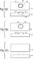
- a method of repairing a component 10, e.g. combustor casing may comprise removing a damaged portion 12 of the component to expose a region of the component.
- the damaged component may be machined such that the damaged affected area, i.e. portion 12, is removed.
- the removal of the damaged portion 12 may leave behind a recess 14, which may be in the form of a standard size semi-elliptical feature.
- the recess 14 may be in the shape of a segment of an ellipsoid and as such may comprise a segment or portion of a sphere, e.g. a hemisphere or any other elliptically shaped recess.
- a bespoke feature could be machined out, e.g. for the purpose of repairing large areas.
- the method may further comprise providing a patch 20.
- the patch 20 may have a rim 22 exceeding the dimensions of the exposed region, e.g. the recess 14.
- the repair patch 20 may be made of the same material as the original component 10.
- the method may further comprise cleaning the patch 20 and/or component 10. For example, the repair patch 20, area within the recess 14 and immediately surrounding area may be cleaned to a level suitable for diffusion bonding.
- the patch 20 may be placed on the exposed region, e.g. recess 14, of the component 10.
- the exposed region, e.g. recess 14, may be covered by the patch and the rim 22 may be spaced apart from the exposed region.
- the repair patch 20 may be shaped such that when it is placed in the recess 14, a portion 20' of the patch fills the entire recess.
- at least the surface of the patch 20 which engages with the component 10 may correspond in shape with the component.
- the underside of the patch 20, e.g. the overhang may be sized and/or shaped to facilitate the manipulation and positioning of the patch prior to and/or during sealing.
- the patch 20 and recess 14 may be in any shape and size and standard patches may be prepared in advance to fill standard shaped and sized recesses.
- the portion 20' of the patch may be in the shape of a segment of an ellipsoid and as such may comprise a segment or portion of a sphere, e.g. a hemisphere or any other elliptically shaped portion.
- the method may further comprise joining the patch 20 to the component 10 around the rim 22 of the patch 20, thereby providing a join 30, e.g. seal, between the patch 20 and component 10.
- the join 30 may provide a fluid tight, e.g. hermetic, seal between the patch 20 and component 10.
- the join 30 may be achieved by welding or brazing the patch 20 to the component 10.
- the join 30 may be formed with minimum penetration into the component and/or with minimum heat input into the component. Accordingly, the join 30 may form a seal around the rim of the patch without molten material penetrating into the recess 14.
- the overhang provided by the overlap of the patch rim 22 over the exposed region may taper in thickness to minimise the thermal section and/or to minimise the heat intensity required for melting/wetting.
- the tapered rim may be in the form of a chamfer, step (e.g. top-hat type arrangement) or any other reduction in thickness around the circumference of the rim 22.
- the overlap of the patch rim 22 over the exposed region may prevent liquid resulting from the sealing process about the rim having a direct passage into the final joint region, e.g. between the recess 14 and the patch 20.
- the heating required to form the join 30 may be localised. Such localised heating may reduce capillary flow by increasing the distance from the final joint region as molten material would have to flow across much cooler material. This increased distance allows time and space for cooling, changing of viscosity and ultimately solidification prior to encroachment into the final joint region.
- the join 30 may be approximately 1 mm wide.
- the overhang provided by the overlap of the patch rim 22 over the exposed region may be approximately equal to or greater than 2mm in width.
- the edge of the rim 22 may be 2mm or more away from the edge of the final joint, e.g. an edge of the recess 14.
- the join 30 between the rim 22 of the patch 20 and the component 10 may be provided under a vacuum. Accordingly, a vacuum may exist between the patch 20 and component 10 once joined together by join 30.
- the vacuum may be provided locally to the patch 20, e.g. the entire component 10 may not be contained within a vacuum.
- a brazing shim may be placed outside the diffusion bonding region. Brazing may take place in a vacuum and may be performed at much lower temperatures than welding.
- the method may further comprise diffusion bonding the patch 20 and the component 10 together.
- the patch and the component may be joined together by Hot Isostatic Pressing (HIP).
- the patch and the component may be joined together used the same HIP cycle (e.g. temperature, pressure, time) as originally used to manufacture the component.
- the repair HIP cycle could be reduced in time or temperature.
- Such a reduced HIP cycle may be sufficient to produce a full diffusion bond between the component and repair patch.
- the repair patch 20 into the recess of the component the subsurface weld should have material properties equal to the original material.
- diffusion bonding the patch to the component enables a very high quality bond between the patch and the component, such that the patch may be indistinguishable from the repair. This cannot be achieved using arc welding techniques alone.
- the diffusion bonding step may be performed under a vacuum and the vacuum may be provided locally to the patch. Furthermore, the vacuum for the joining step may allow the component to be diffusion bonded in a HIP vessel without having to encapsulate the whole component, which would be prohibitively expensive.
- the method may further comprise removing any excess material from the patch 20 after diffusion bonding the patch 20 and component 10 together.
- the join 30 around the rim of the patch 20 may be, at least partially, removed from the component 10.
- the microstructure affected by the provision of the join 30 (for example the melt isotherm or the metallographically determined Heat Affected Zone (as determined by a representative sample)) may be removed by machining, e.g. to a depth to ensure complete removal.
- the excess material may be removed by machining and the machining may be chip-less or chip-forming.
- the repair patch 20 may be blended into the component 10.
- the final profile may be achieved by blending and/or adaptive machining and may include polishing or abrasive blasting. The material removal may not compromise the design requirements of the component.
- the method may further comprise heat treating the component 10 and patch 20, for example to restore the component's original mechanical properties and to appropriately age any welded or brazed material.
- the heat treating may be carried out after the diffusion bonding cycle. Depending on the requirements for dimensional tolerances in the repaired area, the heat treating may be carried out before or after the machining to remove any excess material from the patch 20.
- NDT nonDestructive Testing
- FPI Fluorescent Penetrant Inspection
- X-ray X-ray
- ultrasound thermography techniques
- the present disclosure may relate to a solid state, metal addition process, primarily designed for repair.
- the material added during the process disclosed herein may be used in a load bearing capacity, which is not the case for material added using current repair techniques. Accordingly, an advantage of the present disclosure over current repair methods is that the material added by the method disclosed herein may be used in a load bearing capacity. Furthermore, fusion welding addition methods are likely to cause cracks in the component, either during welding, heat treatment or in service.
- the present disclosure could be applied to any component where a patch may be joined to a damaged region and subsequently diffusion bonded.
- the invention is particularly applicable to components that were originally diffusion bonded and require repair of damaged regions.
- the recess may only be partially filled by the patch and the remainder of the recess may be filled with a powder.
- the powder may have the same composition as the original component, e.g. casing powder feedstock. The method may otherwise proceed as described above.
- the patch may deform into the recess during the HIP cycle, thereby filling the recess.
- the method disclosed herein may also be used to repair protruding parts, e.g. bosses, or any other features that are proud of a component surface.
- the feature to be repaired may be machined flush, e.g. removed from the surface of the component, and a replacement feature may be provided on the outer facing surface of a patch.
- the patch with the replacement feature may comprise a rim shaped to fit on the component.
- the component may not have a recess formed in it and the patch may sit on the component where the original feature had been removed.
- the rim may allow the patch with the new feature to be joined, e.g. sealed, onto the component in a manner similar to that described above, e.g. by welding or brazing.
- the process would then continue as previously mentioned, e.g. the patch may be diffusion bonded to the component. Only the sealing rim may then be removed instead of the above surface feature, and any heat treatment may be as specified for the patch.
Landscapes
- Engineering & Computer Science (AREA)
- Mechanical Engineering (AREA)
- General Engineering & Computer Science (AREA)
- Pressure Welding/Diffusion-Bonding (AREA)
Applications Claiming Priority (1)
| Application Number | Priority Date | Filing Date | Title |
|---|---|---|---|
| GB1103078.0A GB2488333B (en) | 2011-02-23 | 2011-02-23 | A method of repairing a component |
Publications (1)
| Publication Number | Publication Date |
|---|---|
| EP2492044A1 true EP2492044A1 (de) | 2012-08-29 |
Family
ID=43881518
Family Applications (1)
| Application Number | Title | Priority Date | Filing Date |
|---|---|---|---|
| EP12152666A Withdrawn EP2492044A1 (de) | 2011-02-23 | 2012-01-26 | Verfahren zum Reparieren einer Komponente |
Country Status (4)
| Country | Link |
|---|---|
| US (1) | US20120211548A1 (de) |
| EP (1) | EP2492044A1 (de) |
| GB (1) | GB2488333B (de) |
| SG (1) | SG183615A1 (de) |
Cited By (5)
| Publication number | Priority date | Publication date | Assignee | Title |
|---|---|---|---|---|
| WO2013070573A1 (en) * | 2011-11-07 | 2013-05-16 | Siemens Energy, Inc. | Method of joining or repairing superalloy structures using projection resistance brazing : corresponding superalloy component |
| US9272350B2 (en) | 2012-03-30 | 2016-03-01 | Siemens Energy, Inc. | Method for resistance braze repair |
| US9273562B2 (en) | 2011-11-07 | 2016-03-01 | Siemens Energy, Inc. | Projection resistance welding of superalloys |
| EP2674243A3 (de) * | 2012-06-13 | 2016-03-30 | General Electric Company | Verfahren zur Reparatur von Metallgegenständen |
| EP3848142A1 (de) * | 2020-01-08 | 2021-07-14 | General Electric Company | Superlegierungsteil und verfahren zur bearbeitung |
Families Citing this family (10)
| Publication number | Priority date | Publication date | Assignee | Title |
|---|---|---|---|---|
| US20150190891A1 (en) * | 2012-09-28 | 2015-07-09 | United Technologies Corporation | Repair of Casting Defects |
| CN102990219B (zh) * | 2012-11-14 | 2015-01-07 | 北京动力机械研究所 | 一种Ti2AlNb合金材料的燃烧室结构件的扩散焊工艺方法 |
| JP6275411B2 (ja) * | 2013-08-09 | 2018-02-07 | 三菱重工業株式会社 | ろう付方法 |
| US9347899B2 (en) | 2013-12-06 | 2016-05-24 | Rolls-Royce Corporation | Thermographic inspection techniques |
| EP3061558B1 (de) | 2015-02-26 | 2018-04-04 | Airbus Group SAS | Reibrührschweißverfahren zum Reparieren eines Schweißdefekts |
| US20170114466A1 (en) * | 2015-10-21 | 2017-04-27 | General Electric Company | Article, turbine component and airfoil treatment methods |
| US10717167B2 (en) * | 2016-10-10 | 2020-07-21 | Rolls-Royce North American Technologies, Inc. | Machining template |
| US10625361B2 (en) * | 2017-06-14 | 2020-04-21 | General Electric Company | Method of welding superalloys |
| US12053848B1 (en) * | 2023-05-05 | 2024-08-06 | Pratt & Whitney Canada Corp. | Repair methods for components having a damaged portion on a surface thereof |
| FR3162485A1 (fr) * | 2024-05-24 | 2025-11-28 | Safran Aircraft Engines | Peau de réparation pour une plateforme de redresseur de soufflante et procédé de réparation associé |
Citations (8)
| Publication number | Priority date | Publication date | Assignee | Title |
|---|---|---|---|---|
| US5071054A (en) * | 1990-12-18 | 1991-12-10 | General Electric Company | Fabrication of cast articles from high melting temperature superalloy compositions |
| US5390413A (en) | 1992-10-16 | 1995-02-21 | Rolls-Royce Plc | Bladed disc assembly method by hip diffusion bonding |
| EP1127648A2 (de) * | 2000-02-23 | 2001-08-29 | ALSTOM Power (Schweiz) AG | Verfahren zur Reparatur einer Gasturbinenkomponente |
| US20050139581A1 (en) | 2003-12-24 | 2005-06-30 | Yiping Hu | High-strength superalloy joining method for repairing turbine blades |
| JP2005342857A (ja) * | 2004-06-04 | 2005-12-15 | Toshiba Corp | 加圧ろう付補修方法およびガスタービン部品 |
| WO2009001026A1 (en) | 2007-06-22 | 2008-12-31 | Rolls-Royce Plc | A joining and a repair method |
| US20090031564A1 (en) | 2005-11-24 | 2009-02-05 | Reinhold Meier | Method of repairing a shroud segment of a gas turbine |
| US20100059573A1 (en) * | 2008-09-08 | 2010-03-11 | General Electric Company | Process of filling openings in a component |
Family Cites Families (4)
| Publication number | Priority date | Publication date | Assignee | Title |
|---|---|---|---|---|
| US3487530A (en) * | 1967-10-09 | 1970-01-06 | Abex Corp | Method of repairing casting defects |
| US3762032A (en) * | 1971-08-19 | 1973-10-02 | Gen Motors Corp | Bonding |
| US4953777A (en) * | 1986-10-08 | 1990-09-04 | Chromalloy Gas Turbine Corporation | Method for repairing by solid state diffusion metal parts having damaged holes |
| US6454156B1 (en) * | 2000-06-23 | 2002-09-24 | Siemens Westinghouse Power Corporation | Method for closing core printout holes in superalloy gas turbine blades |
-
2011
- 2011-02-23 GB GB1103078.0A patent/GB2488333B/en not_active Expired - Fee Related
-
2012
- 2012-01-26 EP EP12152666A patent/EP2492044A1/de not_active Withdrawn
- 2012-01-26 US US13/359,118 patent/US20120211548A1/en not_active Abandoned
- 2012-02-01 SG SG2012007266A patent/SG183615A1/en unknown
Patent Citations (8)
| Publication number | Priority date | Publication date | Assignee | Title |
|---|---|---|---|---|
| US5071054A (en) * | 1990-12-18 | 1991-12-10 | General Electric Company | Fabrication of cast articles from high melting temperature superalloy compositions |
| US5390413A (en) | 1992-10-16 | 1995-02-21 | Rolls-Royce Plc | Bladed disc assembly method by hip diffusion bonding |
| EP1127648A2 (de) * | 2000-02-23 | 2001-08-29 | ALSTOM Power (Schweiz) AG | Verfahren zur Reparatur einer Gasturbinenkomponente |
| US20050139581A1 (en) | 2003-12-24 | 2005-06-30 | Yiping Hu | High-strength superalloy joining method for repairing turbine blades |
| JP2005342857A (ja) * | 2004-06-04 | 2005-12-15 | Toshiba Corp | 加圧ろう付補修方法およびガスタービン部品 |
| US20090031564A1 (en) | 2005-11-24 | 2009-02-05 | Reinhold Meier | Method of repairing a shroud segment of a gas turbine |
| WO2009001026A1 (en) | 2007-06-22 | 2008-12-31 | Rolls-Royce Plc | A joining and a repair method |
| US20100059573A1 (en) * | 2008-09-08 | 2010-03-11 | General Electric Company | Process of filling openings in a component |
Cited By (7)
| Publication number | Priority date | Publication date | Assignee | Title |
|---|---|---|---|---|
| WO2013070573A1 (en) * | 2011-11-07 | 2013-05-16 | Siemens Energy, Inc. | Method of joining or repairing superalloy structures using projection resistance brazing : corresponding superalloy component |
| US9186740B2 (en) | 2011-11-07 | 2015-11-17 | Siemens Energy, Inc. | Projection resistance brazing of superalloys |
| US9273562B2 (en) | 2011-11-07 | 2016-03-01 | Siemens Energy, Inc. | Projection resistance welding of superalloys |
| US9272350B2 (en) | 2012-03-30 | 2016-03-01 | Siemens Energy, Inc. | Method for resistance braze repair |
| EP2674243A3 (de) * | 2012-06-13 | 2016-03-30 | General Electric Company | Verfahren zur Reparatur von Metallgegenständen |
| EP3848142A1 (de) * | 2020-01-08 | 2021-07-14 | General Electric Company | Superlegierungsteil und verfahren zur bearbeitung |
| US11559847B2 (en) | 2020-01-08 | 2023-01-24 | General Electric Company | Superalloy part and method of processing |
Also Published As
| Publication number | Publication date |
|---|---|
| GB201103078D0 (en) | 2011-04-06 |
| GB2488333B (en) | 2013-06-05 |
| US20120211548A1 (en) | 2012-08-23 |
| GB2488333A (en) | 2012-08-29 |
| SG183615A1 (en) | 2012-09-27 |
Similar Documents
| Publication | Publication Date | Title |
|---|---|---|
| EP2492044A1 (de) | Verfahren zum Reparieren einer Komponente | |
| KR102566105B1 (ko) | 초합금 보수 방법 | |
| US8042723B2 (en) | Method of repair | |
| US20050067466A1 (en) | Crack repair method | |
| CN101987385A (zh) | 用于修理构件的钎焊工艺和材料 | |
| EP0836904A2 (de) | Ersatzverfahren von aus metallischen Legierungen hergestellten Werkstücken, insbesondere Gasturbinenteilen | |
| KR20040107415A (ko) | 터빈 구성요소의 보수 방법과, 이에 의해 보수된 터빈구성요소 | |
| US20150360328A1 (en) | Method for holding brazing material during a brazing operation | |
| EP1844888A1 (de) | Verfahren zum Schweißen aus Superlegierungen hergestellte Komponente oder zum Reparieren eines Risses in einem aus Superlegierungen hergestellten Komponent unter Verwendung des Lötens nach dem Schweissen | |
| RU2572948C2 (ru) | Композитный порошок для соединения или наплавки путем диффузионной пайки деталей из суперсплавов | |
| KR20140089587A (ko) | 돌기 저항 브레이징을 이용한 초합금 구조물 및 대응 초합금 부품을 접합 또는 수리하는 방법 | |
| KR20140089588A (ko) | 초합금의 돌기 저항 용접 | |
| EP1705338B1 (de) | Verfahren zur Reparatur von Komponenten aus Superlegierungen | |
| JP5535799B2 (ja) | 金属部品の補修方法及び補修された金属部品 | |
| JP2007516842A (ja) | タービンブレードを準備するための高強度超合金結合方法 | |
| US20080210741A1 (en) | Weld repair as a combined heat treatment brazing process for metallic components | |
| FR2923741A1 (fr) | Procede de reparation d'une piece thermomecanique par un faisceau de haute energie | |
| CN111230247B (zh) | 一种宽间隙钎焊焊缝控形方法 | |
| JP2005305492A (ja) | 拡散ろう付補修方法およびその補修方法を用いて補修した耐熱部品 | |
| US20090113706A1 (en) | Craze crack repair of combustor liners | |
| US20150190891A1 (en) | Repair of Casting Defects | |
| JP2022527776A (ja) | 複合先端ホウ素ベースの予備焼結プリフォームを使用するタービンコンポーネントの先端補修 | |
| EP2151543A2 (de) | Reparaturverfahren für Gasturbinen unter Verwendung vom Widerstandschweissen mit Wärmeübertragung durch Leitung | |
| KR100899780B1 (ko) | Hip공법을 이용한 연료 분사 노즐용 소재의 제조방법 | |
| RU2595331C1 (ru) | Способ позиционирования лопаток при изготовлении интегрального моноколеса турбины газотурбинного двигателя |
Legal Events
| Date | Code | Title | Description |
|---|---|---|---|
| PUAI | Public reference made under article 153(3) epc to a published international application that has entered the european phase |
Free format text: ORIGINAL CODE: 0009012 |
|
| AK | Designated contracting states |
Kind code of ref document: A1 Designated state(s): AL AT BE BG CH CY CZ DE DK EE ES FI FR GB GR HR HU IE IS IT LI LT LU LV MC MK MT NL NO PL PT RO RS SE SI SK SM TR |
|
| AX | Request for extension of the european patent |
Extension state: BA ME |
|
| 17P | Request for examination filed |
Effective date: 20130128 |
|
| RAP1 | Party data changed (applicant data changed or rights of an application transferred) |
Owner name: ROLLS-ROYCE PLC |
|
| STAA | Information on the status of an ep patent application or granted ep patent |
Free format text: STATUS: THE APPLICATION IS DEEMED TO BE WITHDRAWN |
|
| 18D | Application deemed to be withdrawn |
Effective date: 20150801 |