EP2492071B1 - Moteur de fraisage doté de plusieurs broches - Google Patents
Moteur de fraisage doté de plusieurs broches Download PDFInfo
- Publication number
- EP2492071B1 EP2492071B1 EP12155932.2A EP12155932A EP2492071B1 EP 2492071 B1 EP2492071 B1 EP 2492071B1 EP 12155932 A EP12155932 A EP 12155932A EP 2492071 B1 EP2492071 B1 EP 2492071B1
- Authority
- EP
- European Patent Office
- Prior art keywords
- milling
- milling device
- profile
- spindle
- tool
- Prior art date
- Legal status (The legal status is an assumption and is not a legal conclusion. Google has not performed a legal analysis and makes no representation as to the accuracy of the status listed.)
- Active
Links
Images

Classifications
-
- B—PERFORMING OPERATIONS; TRANSPORTING
- B27—WORKING OR PRESERVING WOOD OR SIMILAR MATERIAL; NAILING OR STAPLING MACHINES IN GENERAL
- B27G—ACCESSORY MACHINES OR APPARATUS FOR WORKING WOOD OR SIMILAR MATERIALS; TOOLS FOR WORKING WOOD OR SIMILAR MATERIALS; SAFETY DEVICES FOR WOOD WORKING MACHINES OR TOOLS
- B27G13/00—Cutter blocks; Other rotary cutting tools
- B27G13/005—Tools composed of two or more rotating discs
- B27G13/007—Tools composed of two or more rotating discs which are adjustable relatively to each other
-
- B—PERFORMING OPERATIONS; TRANSPORTING
- B23—MACHINE TOOLS; METAL-WORKING NOT OTHERWISE PROVIDED FOR
- B23C—MILLING
- B23C3/00—Milling particular work; Special milling operations; Machines therefor
- B23C3/12—Trimming or finishing edges, e.g. deburring welded corners
- B23C3/126—Portable devices or machines for chamfering edges
-
- B—PERFORMING OPERATIONS; TRANSPORTING
- B27—WORKING OR PRESERVING WOOD OR SIMILAR MATERIAL; NAILING OR STAPLING MACHINES IN GENERAL
- B27D—WORKING VENEER OR PLYWOOD
- B27D5/00—Other working of veneer or plywood specially adapted to veneer or plywood
- B27D5/006—Trimming, chamfering or bevelling edgings, e.g. lists
-
- B—PERFORMING OPERATIONS; TRANSPORTING
- B23—MACHINE TOOLS; METAL-WORKING NOT OTHERWISE PROVIDED FOR
- B23C—MILLING
- B23C2270/00—Details of milling machines, milling processes or milling tools not otherwise provided for
- B23C2270/16—Constructions comprising three or more similar components
Definitions
- the invention relates to a Mehrprofilfräsvorraum for machining of preferably plate-shaped workpieces made of wood, wood materials and / or plastics according to the preamble of claim 1.
- a device is known from DE 19915672 known.
- the EP 2 011 614 A1 discloses a milling device comprising two of milling tools with different profiles.
- the first milling tool is in an operating position
- the second milling tool is mounted with a bearing on a sliding cylinder.
- the sliding cylinder is moved forward and the second tool is brought into working position. Since the sliding cylinder does not rotate and the second tool can not be driven independently, the rotation of the first tool is transmitted to the second tool via corresponding surfaces. In such a rotation transmission, there is a risk that the tools could be damaged if the transfer surfaces hit each other at startup.
- the wear is very high, which arises when changing the profiles during the ongoing milling.
- the second tool is connected directly to a ball bearing with the sliding cylinder. Therefore, the second tool must be provided with a corresponding shrink fit, so that a safe operation is guaranteed and the tool can not solve accidentally. Such a type of attachment can be solved usually only by skilled personnel, so replacement of the tools in this construction is also difficult.
- EP 2 363 259 A1 to call Another post-published document is the EP 2 363 259 A1 to call, which relates to a multi-profile milling.
- the movement device is preferably moved electro-pneumatically, electro-hydraulically and / or electromagnetically.
- the device may further comprise a third milling device having a third milling tool with a third machining profile and a third drive spindle, wherein the third milling device is arranged coaxially with the first milling device and the third milling device between the working position and an idle rest position axially to the first milling device is movable.
- a third or even further milling devices due to the improved design by the additional drive spindles, are advantageous in that the processing device as a whole becomes more flexible in the processing of a plurality of different edge shapes.
- the processing device is set up such that the processing profile of the third milling tool superimposes the processing profile of the first and the second milling tool so that the machined workpiece receives the third processing profile when the third milling device is in the working position.
- This further simplifies the construction since the first and second milling devices can remain in the operative position when the third milling device is switched to the working position. This is especially to be seen in comparison to when the second milling device is withdrawn from the working position when the third milling device is brought into working position.
- all drive spindles are designed as hollow shafts, so that material can be saved.
- the rotation of the first drive spindle via a connection with the second and / or third drive spindle, for example.
- top and bottom designates the side of the drive spindles in their axial direction, on which the tools (the tiller) are arranged.
- the opposite direction is called “above”.
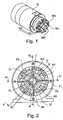
- the invention relates to a Mehrprofilfräsvorraum for preferably plate-shaped workpieces made of wood, wood materials and / or plastics, which is provided for the processing of the narrow sides or the edges of the narrow sides.
- the device includes a motor housing 11, 9, in which a winding (not shown) is provided.
- the housing is designed in several parts with the housing parts 11.1 and 11.2 of the main housing 11 and a cover 9, but a corresponding construction can of course also be designed as a single main housing part 11 with cover 9.
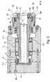
- the housing 11 9 is an axially fixed drive spindle 1, preferably a hollow spindle (hollow shaft) mounted on ball bearings 22.
- a rotor 10 is attached corresponding to the stator windings in the housing part 11.1, which is driven by the windings integrated in the housing 11.
- the stator in the housing 11 and the rotor on the drive spindle 1 thus form a motor for the drive spindle 1 from.
- the first drive spindle 1 is a shaft or hollow shaft driven directly by the motor and drives at least the first tool W1.
- the drive spindle 1 is axially fixed relative to the housing 11 by the housing parts 11.1 and 11.2 are formed in conjunction with the drive spindle 1 accordingly (see, for example. FIG. 3 ).
- the bearings 22 may also be secured in the axial direction with snap-rings or other conventional means.
- a first tool W1 is attached, which has a first milling section F1 with a first Profile, for example, has a radius R3 (3mm).
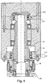
- This tool W1 is preferably fastened with a fastening means 21, in particular screws, on the end face of the axially fixed spindle 1 (see Figures 3 and 4 ).
- the tool W1 is in an operating position and, during operation, mills an edge of the narrow side onto the corresponding workpiece profile on a passing workpiece (in this case, for example, on R3).
- a second spindle 2 (shaft), which is a displaceable hollow spindle (hollow shaft) is mounted on the axially fixed spindle 1 so that it is displaceable in the axial direction relative to the first drive spindle 1.
- a second tool W2 which has a second milling section F2 with a second machining profile, is attached to the second spindle 2 in a torque-proof manner, in the present embodiment a second radius R2 (2 mm).
- the second tool W2 is attached to the end face of the second hollow spindle 2 with fastening means 27, in particular by means of screws.
- the second spindle 2 is rotatably connected to the first drive spindle 1, so that it is in synchronism with the first drive spindle 1.
- such a connection of the second hollow spindle 2 with the first drive spindle 1 is realized via a driver pin 16 (see FIG FIG. 4 ).
- a driver pin 16 see FIG. 4
- the spindle 2 has its own rotor, which is also driven by the stator windings in the housing, possibly also of their own stator windings, which are specially provided for the rotor of the second spindle 2 (which would then also be a drive spindle).
- the axial displaceability is controlled by the moving means.
- this is a sliding cylinder 5 with which the spindle 2 is connected.
- the sliding cylinder 5 for the hollow spindle 2 and thus for the tool W2 is arranged in a sliding space and is in the Figures 3 and 4 to see in its withdrawn position.
- the sliding cylinder 5 is preferably non-rotatably arranged in the housing 11, 9, so that the sliding cylinder can rotate only in the axial direction, but not in the circumferential direction.
- one or more axially extending grooves may be provided in the housing into which engages a projection 5.1 of the sliding cylinder.
- the sliding cylinder 5 is configured rotationally symmetrical, and its friction with the housing wall prevents movement in the circumferential direction (ie, a rotation).
- the projection may in this case be an area with a larger diameter, which is provided around the entire circumference of the cylinder 5.
- the sliding cylinder 5 in the present case is displaced axially by means of compressed air, which is conducted via a pressure line 26 into the displacement chamber.
- a sealing lip 5.2 On the outside of the sliding cylinder 5, therefore, a sealing lip 5.2, for example.
- a rubber ring is provided which seals between the housing 11, 9 (in the present case 11.2) and the sliding cylinder 5 and ensures that no leakage occurs.
- This sealing lip increases the friction in a rotationally symmetrical cylinder, which counteracts a rotation of the sliding cylinder.
- the sliding cylinder 5 for the hollow spindle 2 and thus for the tool W2 is in its sliding space in the Figures 3 and 4 to see in its withdrawn position.
- the sliding cylinder 5 is not, the sliding cylinder is decoupled from the spindle 2 in the circumferential direction via a bearing 23.
- the bearing 23 is fixed in the slide cylinder 5 and with respect to the spindle in the axial direction, so that the displacement force can be transmitted to the spindle 2.
- the storage is realized in the present case by ball bearings, but like all other bearings in this description by others usual storage forms are replaced, which are suitable for the necessary axial force transmission.
- the second spindle is thus preferably arranged between a movement device, preferably the sliding cylinder 5, and the second tool W2.
- the slide cylinder 5 is located at the top of the housing 11, 9, while the spindle 2 for the tool W2 is located at the bottom of the housing 11 with the motor in the axial direction therebetween.
- the sliding cylinder 5 can not be connected directly to the spindle 2 via the bearing 23. Therefore, in the present case, the first axially fixed drive spindle 1 for the first tool W1 is designed as a hollow spindle.
- a further shaft preferably a hollow shaft, is arranged, which is connected at the top with the sliding cylinder 5 via the storage.
- Below the axial movement is preferably transmitted via the or the driving pin (s) 16 to the spindle 2.
- the fluid line 26 may be a spring biasing the slide cylinder so that upon release of the pressure on the slide cylinder 5, this is axially retracted, so that the tool W2 again from the Working position is brought into the neutral position.
- a separate pressure line (not shown) leads into the displacement space under the sliding cylinder 5, which is then subjected to pressure and thus brings the sliding cylinder 5 back into the idling position.
- a generation of vacuum in the overhead fluid channel may be sufficient, so that could be dispensed with an additional element and only the fluid channel 26 is provided.
- the sliding cylinder 5 is controlled by solenoid valves, so that the displacement of the sliding cylinder 5 is magnetic.
- the housing 11, 9 corresponding elements should be provided (not shown in the present embodiment), either two different electromagnetic states are provided for the neutral position and the working position per sliding cylinder, or the sliding cylinders are biased by a spring in neutral position and the electromagnetic force to bring the sliding cylinder, or the tools only in working position and the spring force back into the neutral position.
- the third tool W3 is seated on a displaceable spindle 3, which is designed as a hollow spindle and is different from the displaceable spindle 2.
- the displaceable spindle 3 is arranged in the axial direction over the displaceable spindle 2 and is connected via a sliding cylinder 4 of the. Neutral position brought into the working position (in the FIGS. 3 to 5 the spindle 3 is shown in working position).
- a fluid channel 24 is provided in the present embodiment, which brings the sliding cylinder 4 in the working position (see Figures 3 and 4 ).
- the control and the design of the sliding cylinder 4 is preferably carried out analogously to the above-described control and construction of the sliding cylinder 5, including the Embodiment of the sliding cylinder 4 with a projection 4.1 and sealing lip 4.2.
- a magnetic is also possible.
- the third spindle is thus preferably arranged between a movement device, preferably the sliding cylinder 4, and the third tool W3.
- the displaceable spindle 3 has a driving pin (in one piece or as a separate element), which passes through the axially fixed spindle 1 and thus takes over the rotation of the axially fixed spindle.
- the tool W3 is also preferably fastened with fastening means on the front side of the displaceable spindle 3, wherein the fastening means are preferably screws.
- the displaceable spindles 2 and 3 each rotate with the axially fixed spindle, wherein the sliding cylinders 4 and 5 only move axially and are each connected via ball bearings 23, 25 with the respective spindles 2 and 3.
- the diameter D (shown in FIG. 2 ) of the respective milling sections F1, F2, F3 of the tools W1, W2, W3 (etc.) indicating the distance between the cutting profiles is the same, so that the narrower profile of radius R2 of the tool W2 is the profile of radius R3 of the tool W1 superimposed when both are in working position.
- the multi-profile milling device is thus set up such that the machining profile of the second milling tool superimposes the machining profile of the first tool such that the machined workpiece receives the second machining profile when the second milling device is in the working position. This ensures that, although both tools are working on a workpiece at the same time, only the profile of the tool W2 is transferred to the machined workpiece.
- the tool W3 preferably has a machining profile which superimposes both the machining profile of the tool W1 and the second tool W2.
- the tool W1 In general, depending on the desired machining profile, only the tool W1, and also the tool W2 or, in addition, the tool W3, will be brought into working position. In another preferred embodiment, the tool W2 is retracted when the tool W3 is brought into working position, so that the tool W3 only superimposes the machining profile of the tool W1. It is also advantageous that the tools W2 and W3 in this case always rotate together with the tool W1, so that during processing, the machining profile can be changed without the machine must be stopped. This is made possible, on the one hand, by the sliding cylinders, which are fixed axially together with the displaceable spindles, which, however, are movable in the direction of rotation relative to the hollow spindles, or do not have their own rotation with respect to the housing. On the other hand by the rotationally fixed connection (driving pins 15, 16) of the axially movable spindles 2, 3 with the axially fixed drive spindle. 1
- each drive spindle 1, 2, 3 If, as mentioned above, a separate rotor is provided for each drive spindle 1, 2, 3, then the respective drive spindle does not have to rotate with the first drive spindle 1, and the drive pins can be omitted if they are provided only for receiving the rotation , The respective drive spindles 2, 3 can then be in a rest position and switched to idle if necessary. Afterwards, ie when the drive spindles 2, 3 are in synchronism with the first drive spindle 1, then the corresponding tool W2, W3 can be brought into working position.
- the individual milling tools with different machining profiles are each arranged coaxially and have milling sections F1, F2, F3, with the respective machining profiles.
- the individual tools are each attached to the associated (drive) spindles 1, 2, 3, preferably at their front side.
- the fastening means 21, 27, 28 are preferably screws, wherein the fastening means are preferably arranged off-center, so that by the rotation of the (drive) spindle 1, 2, 3 and the tools W1, W2, W3, the fastening means do not accidentally open can.
- any tool when any tool is to be replaced, first the first tool W1 must be removed so that the second tool W2 can be accessed (see Figures 2 and 3 ). The same applies if the tool W3 is to be replaced, for the tool W2. That is, the tool W2.muss must be removed before the tool W3 can be removed. Then the corresponding tool is exchanged and again attached in reverse order to the processing device respectively to the associated hollow spindles.
- At least one second tool W2 such that it has in its main body a hole with a diameter which is larger than the outer diameter of the first tool (including the milling sections F1). Because the first tool, as in FIG. 2 is formed of a main body H1 and the milling sections F1, which in the present case extend at equal intervals radially outward from the main body H1, could in a tool W2, whose main body H2 has the hole with an inner diameter which is larger than that Outer diameter of the milling sections F1 is, are also removed, without the tool W1 would have to be removed first.
- the third tool W3 (and any other) at least the first or second tool W1, W2 would have to be removed as long as the milling sections, or the cutting profile should have the same diameter D. If this requirement is eliminated, it is possible to form the milling tools W1, W2, W3, etc., each with a main body H1, H2, H3, with a recess or a hole in such a way that they can always be removed individually.
Landscapes
- Life Sciences & Earth Sciences (AREA)
- Engineering & Computer Science (AREA)
- Mechanical Engineering (AREA)
- Wood Science & Technology (AREA)
- Forests & Forestry (AREA)
- Milling Processes (AREA)
- Drilling And Boring (AREA)
- Turning (AREA)
Claims (7)
- Dispositif de fraisage à profils multiples pour usiner par enlèvement de copeaux des pièces présentant de manière préférée une forme de panneau, en bois, en des matériaux dérivés du bois et/ou en matières synthétiques, en particulier pour usiner les chants des tranches de pièces, comprenant :un premier système de fraisage, qui présente un premier outil de fraisage (W1) présentant un premier profil d'usinage et une première broche d'entraînement (1), dans lequel le premier système de fraisage est disposé dans une position de travail ;au moins un deuxième système de fraisage, qui présente un deuxième outil de fraisage (W2) présentant un deuxième profil d'usinage et qui peut être déplacé entre une position de travail et une position de marche à vide/de repos ;un moteur (10) pour entraîner la première broche d'entraînement (1) ;un système de déplacement (5, 26), qui est mis au point afin de déplacer au moins le deuxième système de fraisage entre la position de travail et la position de marche à vide ;un boîtier (9, 11), dans lequel les systèmes de fraisage, le système de déplacement (5, 26) et le moteur (10) sont logés ;le deuxième système de fraisage présentant au moins une deuxième broche (2), dans lequel le deuxième système de fraisage est disposé de manière coaxiale avec le premier système de fraisage,caractérisé en ce
que le système de déplacement (5, 26) est disposé dans la direction axiale au niveau du côté, faisant face aux outils de fraisage (W1, W2), du moteur (10) et est relié à la broche (2) par l'intermédiaire d'un arbre (6), en particulier d'un arbre creux, qui est disposé dans la première broche d'entraînement (1), ou en ce que l'arbre (6) est réalisé d'un seul tenant avec la broche (2). - Dispositif de fraisage à profils multiples selon la revendication 1, dans lequel le système de déplacement est déplacé de manière (électro)-pneumatique, (électro)-hydraulique et/ou (électro)-magnétique.
- Dispositif de fraisage à profils multiples selon la revendication 1 ou 2, lequel présente un troisième système de fraisage, qui présente un troisième outil de fraisage (W3) présentant un troisième profil d'usinage et qui présente une troisième broche (3), dans lequel le troisième système de fraisage est disposé de manière coaxiale avec le premier système de fraisage et le troisième système de fraisage peut être déplacé de manière relative entre la position de travail et une position de marche à vide/de repos de manière axiale par rapport au premier système de fraisage.
- Dispositif de fraisage à profils multiples selon la revendication 3, dans lequel le profil d'usinage du troisième outil de fraisage (W3) surmonte le profil d'usinage du premier et du deuxième outil de fraisage (W1, W2) de telle sorte que la pièce usinée reçoit le troisième profil d'usinage quand le troisième système de fraisage se trouve dans la position de travail.
- Dispositif de fraisage à profils multiples selon la revendication 3 ou 4, dans lequel le deuxième et le troisième système de fraisage sont mis au point de telle sorte qu'ils ne sont pas ensemble dans la position de travail ou où le deuxième et le troisième système de fraisage sont mis au point de telle sorte qu'ils sont ensemble dans la position de travail.
- Dispositif de fraisage à profils multiples selon l'une quelconque des revendications précédentes, dans lequel au moins une des broches (d'entraînement) (1, 2, 3) est configurée sous la forme d'un arbre profilé creux.
- Dispositif de fraisage à profils multiples selon l'une quelconque des revendications précédentes, dans lequel la rotation de la première broche d'entraînement (1) est transmise par l'intermédiaire d'une ou de plusieurs tiges entraîneuses (15, 16) sur l'autre broche/les autres broches et/ou où la/les autre(s) broche(s) d'entraînement est/sont entraînée(s) par l'intermédiaire d'un ou de plusieurs moteurs séparés.
Applications Claiming Priority (1)
| Application Number | Priority Date | Filing Date | Title |
|---|---|---|---|
| DE102011004536A DE102011004536A1 (de) | 2011-02-22 | 2011-02-22 | Fräsmotor mit mehreren Spindeln und einzeln austauschbaren Werkzeugen |
Publications (3)
| Publication Number | Publication Date |
|---|---|
| EP2492071A2 EP2492071A2 (fr) | 2012-08-29 |
| EP2492071A3 EP2492071A3 (fr) | 2014-06-25 |
| EP2492071B1 true EP2492071B1 (fr) | 2016-10-26 |
Family
ID=45656031
Family Applications (1)
| Application Number | Title | Priority Date | Filing Date |
|---|---|---|---|
| EP12155932.2A Active EP2492071B1 (fr) | 2011-02-22 | 2012-02-17 | Moteur de fraisage doté de plusieurs broches |
Country Status (5)
| Country | Link |
|---|---|
| EP (1) | EP2492071B1 (fr) |
| CN (1) | CN102649284B (fr) |
| BR (1) | BR102012003854B1 (fr) |
| DE (1) | DE102011004536A1 (fr) |
| ES (1) | ES2610961T3 (fr) |
Cited By (1)
| Publication number | Priority date | Publication date | Assignee | Title |
|---|---|---|---|---|
| EP3944939A1 (fr) | 2020-07-31 | 2022-02-02 | Ledermann GmbH & Co. KG | Unité d'outils et système d'outils commutables pour une telle unité d'outils |
Families Citing this family (10)
| Publication number | Priority date | Publication date | Assignee | Title |
|---|---|---|---|---|
| DE102013226214A1 (de) | 2013-12-17 | 2015-06-18 | Homag Holzbearbeitungssysteme Gmbh | Bearbeitungsvorrichtung |
| DE102014008033B4 (de) | 2014-06-03 | 2018-03-29 | Leitz Gmbh & Co. Kg | Fräswerkzeug |
| DE202014011134U1 (de) | 2014-06-03 | 2018-01-18 | Leitz Gmbh & Co. Kg | Fräswerkzeug |
| CN104842423A (zh) * | 2015-05-19 | 2015-08-19 | 朱德金 | 一种杆状物料旋切机构 |
| CN104890077A (zh) * | 2015-06-05 | 2015-09-09 | 李广连 | 一种齿轮驱动式木板旋割座 |
| CN105773771A (zh) * | 2016-05-06 | 2016-07-20 | 博艳萍 | 一种手摇式旋切轮驱动机构 |
| PT3354386T (pt) | 2017-01-25 | 2021-03-24 | Ledermann Gmbh & Co Kg | Cabeça porta-ferramenta e sistema de ferramentas com uma cabeça porta-ferramenta |
| DE102017123681C5 (de) * | 2017-10-11 | 2022-01-27 | Leitz Gmbh & Co. Kg | Fräswerkzeug zum Bearbeiten von Holz, Holzwerkstoffen, Kunststoffen oder Leichtmetallen |
| DE202017007479U1 (de) | 2017-10-11 | 2022-01-28 | LEITZ GmbH & Co.KG | Fräswerkzeug zum Bearbeiten von Holz, Holzwerkstoffen, Kunststoffen oder Leichtmetallen |
| CN114523532B (zh) * | 2022-01-20 | 2022-08-19 | 顺德职业技术学院 | 一种木工加工用的刀具定位装置 |
Family Cites Families (10)
| Publication number | Priority date | Publication date | Assignee | Title |
|---|---|---|---|---|
| DE2321292A1 (de) * | 1973-04-27 | 1974-11-14 | Weniger & Co | Vorrichtung zur kantenreinigung von beidseitig beschichteten spanplatten od. dgl |
| US3901295A (en) * | 1974-10-15 | 1975-08-26 | Dart Ind Inc | Trimming apparatus |
| CN2115877U (zh) * | 1992-02-18 | 1992-09-16 | 傅敬中 | 一种香芯机 |
| JPH1128704A (ja) * | 1997-07-09 | 1999-02-02 | Kanefusa Corp | 刃先にランドを有するフライス |
| DE19915672C2 (de) * | 1999-04-07 | 2002-05-29 | Homag Maschinenbau Ag | Vorrichtung zum Bearbeiten von Kanten eines plattenförmigen Werkstückes mit mehreren Spanwerkzeugen |
| DE10341463A1 (de) * | 2003-09-09 | 2005-04-21 | Ledermann & Co | Fräsaggregat und Verfahren zur Kantenbearbeitung von plattenförmigen Werkstücken |
| ITMO20070226A1 (it) | 2007-07-06 | 2009-01-07 | Scm Group Spa | Apparato per fresare |
| CN201309191Y (zh) * | 2008-11-04 | 2009-09-16 | 尤溪县三恒竹木制品有限公司 | 竹木产品外圆铣削机 |
| IT1398754B1 (it) * | 2010-03-02 | 2013-03-18 | Scm Group Spa | Apparato per fresare |
| DE202010010704U1 (de) * | 2010-07-27 | 2011-11-14 | Ledermann Gmbh & Co. Kg | Bearbeitungsvorrichtung |
-
2011
- 2011-02-22 DE DE102011004536A patent/DE102011004536A1/de active Pending
-
2012
- 2012-02-17 EP EP12155932.2A patent/EP2492071B1/fr active Active
- 2012-02-17 ES ES12155932.2T patent/ES2610961T3/es active Active
- 2012-02-22 BR BR102012003854-4A patent/BR102012003854B1/pt not_active IP Right Cessation
- 2012-02-22 CN CN201210042115.8A patent/CN102649284B/zh active Active
Non-Patent Citations (1)
| Title |
|---|
| None * |
Cited By (2)
| Publication number | Priority date | Publication date | Assignee | Title |
|---|---|---|---|---|
| EP3944939A1 (fr) | 2020-07-31 | 2022-02-02 | Ledermann GmbH & Co. KG | Unité d'outils et système d'outils commutables pour une telle unité d'outils |
| US11701718B2 (en) | 2020-07-31 | 2023-07-18 | Ledermann Gmbh & Co. Kg | Tool unit and switchable tool system for a tool unit |
Also Published As
| Publication number | Publication date |
|---|---|
| DE102011004536A1 (de) | 2012-08-23 |
| BR102012003854A2 (pt) | 2013-11-05 |
| BR102012003854B1 (pt) | 2021-03-23 |
| ES2610961T3 (es) | 2017-05-04 |
| EP2492071A2 (fr) | 2012-08-29 |
| EP2492071A3 (fr) | 2014-06-25 |
| CN102649284B (zh) | 2016-01-20 |
| CN102649284A (zh) | 2012-08-29 |
Similar Documents
| Publication | Publication Date | Title |
|---|---|---|
| EP2492071B1 (fr) | Moteur de fraisage doté de plusieurs broches | |
| EP2603340B1 (fr) | Porte-outil | |
| DE102017121294B4 (de) | Spindeleinheit für Werkzeugmaschinen | |
| EP0970770A1 (fr) | Dispositif et procédé pour l'usinage d'un alésage | |
| DE112007001338T5 (de) | Drehschieberpumpe zum Pumpen von Hydraulikfluid | |
| DE19525343A1 (de) | Vorrichtung zum Überführen von Fluid zwischen relativ zueinander drehbaren Maschinenteilen | |
| WO2010054637A1 (fr) | Outil de finition d'alésage par enlèvement de copeaux, à plusieurs tranchants | |
| WO2018046036A2 (fr) | Outil d'usinage par enlèvement de copeaux multi-lames et procédé d'usinage d'un chemin laser | |
| DE4341167A1 (de) | Einrichtung zur Übertragung eines Druckmediums | |
| DE2501020A1 (de) | Klemmkupplung zum starren verbinden einer antriebsbuchse mit einer darin verschiebbar gefuehrten spindel | |
| WO2017140499A1 (fr) | Cylindre à pas constant pour installations d'extrusion | |
| DE102009033528A1 (de) | Kombinationswerkzeug | |
| EP1360135A1 (fr) | Cylindre a lames de pliage d'une machine de pliage et procede de reglage d'une lame de pliage | |
| DE2340125A1 (de) | Maschine zum profilwalzen von ringen | |
| DE2028932A1 (de) | Schaltvorrichtung insbesondere fur Bohr spindeln | |
| EP3509780B1 (fr) | Porte-lame et outil d'usinage par enlèvement de copeaux comportant un porte-lame | |
| DE3613882C1 (de) | Mehrspindel-Drehmaschine | |
| EP0974782B1 (fr) | Dispositif d'alimentation d'un fluide sous pression | |
| DE2709448C3 (de) | Bohrspindeleinheit | |
| EP1163976A1 (fr) | Entrainement avec une transmission variable pour un dispositif porte outil | |
| DE4008204C2 (fr) | ||
| DE399114C (de) | Flaechenschleifmaschine | |
| EP1574275A2 (fr) | Cylindre de serrage | |
| DE2953287A1 (en) | Motion translation apparatus | |
| EP1882855A2 (fr) | Moteur hydraulique |
Legal Events
| Date | Code | Title | Description |
|---|---|---|---|
| PUAI | Public reference made under article 153(3) epc to a published international application that has entered the european phase |
Free format text: ORIGINAL CODE: 0009012 |
|
| AK | Designated contracting states |
Kind code of ref document: A2 Designated state(s): AL AT BE BG CH CY CZ DE DK EE ES FI FR GB GR HR HU IE IS IT LI LT LU LV MC MK MT NL NO PL PT RO RS SE SI SK SM TR |
|
| AX | Request for extension of the european patent |
Extension state: BA ME |
|
| PUAL | Search report despatched |
Free format text: ORIGINAL CODE: 0009013 |
|
| AK | Designated contracting states |
Kind code of ref document: A3 Designated state(s): AL AT BE BG CH CY CZ DE DK EE ES FI FR GB GR HR HU IE IS IT LI LT LU LV MC MK MT NL NO PL PT RO RS SE SI SK SM TR |
|
| AX | Request for extension of the european patent |
Extension state: BA ME |
|
| RIC1 | Information provided on ipc code assigned before grant |
Ipc: B27G 13/00 20060101ALI20140522BHEP Ipc: B27D 5/00 20060101AFI20140522BHEP Ipc: B23C 3/12 20060101ALI20140522BHEP |
|
| 17P | Request for examination filed |
Effective date: 20141017 |
|
| RBV | Designated contracting states (corrected) |
Designated state(s): AL AT BE BG CH CY CZ DE DK EE ES FI FR GB GR HR HU IE IS IT LI LT LU LV MC MK MT NL NO PL PT RO RS SE SI SK SM TR |
|
| GRAP | Despatch of communication of intention to grant a patent |
Free format text: ORIGINAL CODE: EPIDOSNIGR1 |
|
| INTG | Intention to grant announced |
Effective date: 20160413 |
|
| GRAJ | Information related to disapproval of communication of intention to grant by the applicant or resumption of examination proceedings by the epo deleted |
Free format text: ORIGINAL CODE: EPIDOSDIGR1 |
|
| GRAR | Information related to intention to grant a patent recorded |
Free format text: ORIGINAL CODE: EPIDOSNIGR71 |
|
| GRAS | Grant fee paid |
Free format text: ORIGINAL CODE: EPIDOSNIGR3 |
|
| GRAA | (expected) grant |
Free format text: ORIGINAL CODE: 0009210 |
|
| INTC | Intention to grant announced (deleted) | ||
| RAP1 | Party data changed (applicant data changed or rights of an application transferred) |
Owner name: HOMAG GMBH |
|
| INTG | Intention to grant announced |
Effective date: 20160913 |
|
| AK | Designated contracting states |
Kind code of ref document: B1 Designated state(s): AL AT BE BG CH CY CZ DE DK EE ES FI FR GB GR HR HU IE IS IT LI LT LU LV MC MK MT NL NO PL PT RO RS SE SI SK SM TR |
|
| REG | Reference to a national code |
Ref country code: GB Ref legal event code: FG4D Free format text: NOT ENGLISH |
|
| REG | Reference to a national code |
Ref country code: CH Ref legal event code: EP |
|
| REG | Reference to a national code |
Ref country code: AT Ref legal event code: REF Ref document number: 839674 Country of ref document: AT Kind code of ref document: T Effective date: 20161115 |
|
| REG | Reference to a national code |
Ref country code: IE Ref legal event code: FG4D Free format text: LANGUAGE OF EP DOCUMENT: GERMAN |
|
| REG | Reference to a national code |
Ref country code: DE Ref legal event code: R096 Ref document number: 502012008611 Country of ref document: DE |
|
| REG | Reference to a national code |
Ref country code: LT Ref legal event code: MG4D |
|
| PG25 | Lapsed in a contracting state [announced via postgrant information from national office to epo] |
Ref country code: LV Free format text: LAPSE BECAUSE OF FAILURE TO SUBMIT A TRANSLATION OF THE DESCRIPTION OR TO PAY THE FEE WITHIN THE PRESCRIBED TIME-LIMIT Effective date: 20161026 |
|
| REG | Reference to a national code |
Ref country code: NL Ref legal event code: MP Effective date: 20161026 |
|
| PG25 | Lapsed in a contracting state [announced via postgrant information from national office to epo] |
Ref country code: NO Free format text: LAPSE BECAUSE OF FAILURE TO SUBMIT A TRANSLATION OF THE DESCRIPTION OR TO PAY THE FEE WITHIN THE PRESCRIBED TIME-LIMIT Effective date: 20170126 Ref country code: SE Free format text: LAPSE BECAUSE OF FAILURE TO SUBMIT A TRANSLATION OF THE DESCRIPTION OR TO PAY THE FEE WITHIN THE PRESCRIBED TIME-LIMIT Effective date: 20161026 Ref country code: GR Free format text: LAPSE BECAUSE OF FAILURE TO SUBMIT A TRANSLATION OF THE DESCRIPTION OR TO PAY THE FEE WITHIN THE PRESCRIBED TIME-LIMIT Effective date: 20170127 Ref country code: LT Free format text: LAPSE BECAUSE OF FAILURE TO SUBMIT A TRANSLATION OF THE DESCRIPTION OR TO PAY THE FEE WITHIN THE PRESCRIBED TIME-LIMIT Effective date: 20161026 |
|
| REG | Reference to a national code |
Ref country code: ES Ref legal event code: FG2A Ref document number: 2610961 Country of ref document: ES Kind code of ref document: T3 Effective date: 20170504 |
|
| PG25 | Lapsed in a contracting state [announced via postgrant information from national office to epo] |
Ref country code: NL Free format text: LAPSE BECAUSE OF FAILURE TO SUBMIT A TRANSLATION OF THE DESCRIPTION OR TO PAY THE FEE WITHIN THE PRESCRIBED TIME-LIMIT Effective date: 20161026 Ref country code: FI Free format text: LAPSE BECAUSE OF FAILURE TO SUBMIT A TRANSLATION OF THE DESCRIPTION OR TO PAY THE FEE WITHIN THE PRESCRIBED TIME-LIMIT Effective date: 20161026 Ref country code: RS Free format text: LAPSE BECAUSE OF FAILURE TO SUBMIT A TRANSLATION OF THE DESCRIPTION OR TO PAY THE FEE WITHIN THE PRESCRIBED TIME-LIMIT Effective date: 20161026 Ref country code: HR Free format text: LAPSE BECAUSE OF FAILURE TO SUBMIT A TRANSLATION OF THE DESCRIPTION OR TO PAY THE FEE WITHIN THE PRESCRIBED TIME-LIMIT Effective date: 20161026 Ref country code: PL Free format text: LAPSE BECAUSE OF FAILURE TO SUBMIT A TRANSLATION OF THE DESCRIPTION OR TO PAY THE FEE WITHIN THE PRESCRIBED TIME-LIMIT Effective date: 20161026 Ref country code: PT Free format text: LAPSE BECAUSE OF FAILURE TO SUBMIT A TRANSLATION OF THE DESCRIPTION OR TO PAY THE FEE WITHIN THE PRESCRIBED TIME-LIMIT Effective date: 20170227 Ref country code: IS Free format text: LAPSE BECAUSE OF FAILURE TO SUBMIT A TRANSLATION OF THE DESCRIPTION OR TO PAY THE FEE WITHIN THE PRESCRIBED TIME-LIMIT Effective date: 20170226 Ref country code: BE Free format text: LAPSE BECAUSE OF NON-PAYMENT OF DUE FEES Effective date: 20170228 |
|
| REG | Reference to a national code |
Ref country code: DE Ref legal event code: R097 Ref document number: 502012008611 Country of ref document: DE |
|
| PG25 | Lapsed in a contracting state [announced via postgrant information from national office to epo] |
Ref country code: CZ Free format text: LAPSE BECAUSE OF FAILURE TO SUBMIT A TRANSLATION OF THE DESCRIPTION OR TO PAY THE FEE WITHIN THE PRESCRIBED TIME-LIMIT Effective date: 20161026 Ref country code: RO Free format text: LAPSE BECAUSE OF FAILURE TO SUBMIT A TRANSLATION OF THE DESCRIPTION OR TO PAY THE FEE WITHIN THE PRESCRIBED TIME-LIMIT Effective date: 20161026 Ref country code: EE Free format text: LAPSE BECAUSE OF FAILURE TO SUBMIT A TRANSLATION OF THE DESCRIPTION OR TO PAY THE FEE WITHIN THE PRESCRIBED TIME-LIMIT Effective date: 20161026 Ref country code: DK Free format text: LAPSE BECAUSE OF FAILURE TO SUBMIT A TRANSLATION OF THE DESCRIPTION OR TO PAY THE FEE WITHIN THE PRESCRIBED TIME-LIMIT Effective date: 20161026 Ref country code: SK Free format text: LAPSE BECAUSE OF FAILURE TO SUBMIT A TRANSLATION OF THE DESCRIPTION OR TO PAY THE FEE WITHIN THE PRESCRIBED TIME-LIMIT Effective date: 20161026 |
|
| PG25 | Lapsed in a contracting state [announced via postgrant information from national office to epo] |
Ref country code: SM Free format text: LAPSE BECAUSE OF FAILURE TO SUBMIT A TRANSLATION OF THE DESCRIPTION OR TO PAY THE FEE WITHIN THE PRESCRIBED TIME-LIMIT Effective date: 20161026 Ref country code: BG Free format text: LAPSE BECAUSE OF FAILURE TO SUBMIT A TRANSLATION OF THE DESCRIPTION OR TO PAY THE FEE WITHIN THE PRESCRIBED TIME-LIMIT Effective date: 20170126 |
|
| PLBE | No opposition filed within time limit |
Free format text: ORIGINAL CODE: 0009261 |
|
| STAA | Information on the status of an ep patent application or granted ep patent |
Free format text: STATUS: NO OPPOSITION FILED WITHIN TIME LIMIT |
|
| PG25 | Lapsed in a contracting state [announced via postgrant information from national office to epo] |
Ref country code: MC Free format text: LAPSE BECAUSE OF FAILURE TO SUBMIT A TRANSLATION OF THE DESCRIPTION OR TO PAY THE FEE WITHIN THE PRESCRIBED TIME-LIMIT Effective date: 20161026 |
|
| REG | Reference to a national code |
Ref country code: CH Ref legal event code: PL |
|
| 26N | No opposition filed |
Effective date: 20170727 |
|
| GBPC | Gb: european patent ceased through non-payment of renewal fee |
Effective date: 20170217 |
|
| PG25 | Lapsed in a contracting state [announced via postgrant information from national office to epo] |
Ref country code: LI Free format text: LAPSE BECAUSE OF NON-PAYMENT OF DUE FEES Effective date: 20170228 Ref country code: CH Free format text: LAPSE BECAUSE OF NON-PAYMENT OF DUE FEES Effective date: 20170228 |
|
| REG | Reference to a national code |
Ref country code: IE Ref legal event code: MM4A |
|
| PG25 | Lapsed in a contracting state [announced via postgrant information from national office to epo] |
Ref country code: SI Free format text: LAPSE BECAUSE OF FAILURE TO SUBMIT A TRANSLATION OF THE DESCRIPTION OR TO PAY THE FEE WITHIN THE PRESCRIBED TIME-LIMIT Effective date: 20161026 |
|
| REG | Reference to a national code |
Ref country code: FR Ref legal event code: ST Effective date: 20171031 |
|
| PG25 | Lapsed in a contracting state [announced via postgrant information from national office to epo] |
Ref country code: LU Free format text: LAPSE BECAUSE OF NON-PAYMENT OF DUE FEES Effective date: 20170217 |
|
| PG25 | Lapsed in a contracting state [announced via postgrant information from national office to epo] |
Ref country code: FR Free format text: LAPSE BECAUSE OF NON-PAYMENT OF DUE FEES Effective date: 20170228 |
|
| REG | Reference to a national code |
Ref country code: BE Ref legal event code: MM Effective date: 20170228 |
|
| PG25 | Lapsed in a contracting state [announced via postgrant information from national office to epo] |
Ref country code: IE Free format text: LAPSE BECAUSE OF NON-PAYMENT OF DUE FEES Effective date: 20170217 Ref country code: GB Free format text: LAPSE BECAUSE OF NON-PAYMENT OF DUE FEES Effective date: 20170217 |
|
| PG25 | Lapsed in a contracting state [announced via postgrant information from national office to epo] |
Ref country code: MT Free format text: LAPSE BECAUSE OF FAILURE TO SUBMIT A TRANSLATION OF THE DESCRIPTION OR TO PAY THE FEE WITHIN THE PRESCRIBED TIME-LIMIT Effective date: 20161026 |
|
| PG25 | Lapsed in a contracting state [announced via postgrant information from national office to epo] |
Ref country code: HU Free format text: LAPSE BECAUSE OF FAILURE TO SUBMIT A TRANSLATION OF THE DESCRIPTION OR TO PAY THE FEE WITHIN THE PRESCRIBED TIME-LIMIT; INVALID AB INITIO Effective date: 20120217 |
|
| PG25 | Lapsed in a contracting state [announced via postgrant information from national office to epo] |
Ref country code: CY Free format text: LAPSE BECAUSE OF NON-PAYMENT OF DUE FEES Effective date: 20161026 |
|
| PG25 | Lapsed in a contracting state [announced via postgrant information from national office to epo] |
Ref country code: MK Free format text: LAPSE BECAUSE OF FAILURE TO SUBMIT A TRANSLATION OF THE DESCRIPTION OR TO PAY THE FEE WITHIN THE PRESCRIBED TIME-LIMIT Effective date: 20161026 |
|
| PG25 | Lapsed in a contracting state [announced via postgrant information from national office to epo] |
Ref country code: TR Free format text: LAPSE BECAUSE OF FAILURE TO SUBMIT A TRANSLATION OF THE DESCRIPTION OR TO PAY THE FEE WITHIN THE PRESCRIBED TIME-LIMIT Effective date: 20161026 |
|
| PG25 | Lapsed in a contracting state [announced via postgrant information from national office to epo] |
Ref country code: AL Free format text: LAPSE BECAUSE OF FAILURE TO SUBMIT A TRANSLATION OF THE DESCRIPTION OR TO PAY THE FEE WITHIN THE PRESCRIBED TIME-LIMIT Effective date: 20161026 |
|
| PGFP | Annual fee paid to national office [announced via postgrant information from national office to epo] |
Ref country code: ES Payment date: 20210303 Year of fee payment: 10 |
|
| REG | Reference to a national code |
Ref country code: ES Ref legal event code: FD2A Effective date: 20230428 |
|
| P01 | Opt-out of the competence of the unified patent court (upc) registered |
Effective date: 20230529 |
|
| PG25 | Lapsed in a contracting state [announced via postgrant information from national office to epo] |
Ref country code: ES Free format text: LAPSE BECAUSE OF NON-PAYMENT OF DUE FEES Effective date: 20220218 |
|
| PGFP | Annual fee paid to national office [announced via postgrant information from national office to epo] |
Ref country code: DE Payment date: 20260225 Year of fee payment: 15 |
|
| PGFP | Annual fee paid to national office [announced via postgrant information from national office to epo] |
Ref country code: AT Payment date: 20260225 Year of fee payment: 15 |
|
| PGFP | Annual fee paid to national office [announced via postgrant information from national office to epo] |
Ref country code: IT Payment date: 20260225 Year of fee payment: 15 |