EP2492079B1 - Refroidissement d'insert de cavité de préforme - Google Patents
Refroidissement d'insert de cavité de préforme Download PDFInfo
- Publication number
- EP2492079B1 EP2492079B1 EP20120001286 EP12001286A EP2492079B1 EP 2492079 B1 EP2492079 B1 EP 2492079B1 EP 20120001286 EP20120001286 EP 20120001286 EP 12001286 A EP12001286 A EP 12001286A EP 2492079 B1 EP2492079 B1 EP 2492079B1
- Authority
- EP
- European Patent Office
- Prior art keywords
- chamber
- cavity insert
- cooling
- cavity
- cooling fluid
- Prior art date
- Legal status (The legal status is an assumption and is not a legal conclusion. Google has not performed a legal analysis and makes no representation as to the accuracy of the status listed.)
- Not-in-force
Links
Images



Classifications
-
- B—PERFORMING OPERATIONS; TRANSPORTING
- B29—WORKING OF PLASTICS; WORKING OF SUBSTANCES IN A PLASTIC STATE IN GENERAL
- B29C—SHAPING OR JOINING OF PLASTICS; SHAPING OF MATERIAL IN A PLASTIC STATE, NOT OTHERWISE PROVIDED FOR; AFTER-TREATMENT OF THE SHAPED PRODUCTS, e.g. REPAIRING
- B29C33/00—Moulds or cores; Details thereof or accessories therefor
- B29C33/02—Moulds or cores; Details thereof or accessories therefor with incorporated heating or cooling means
-
- B—PERFORMING OPERATIONS; TRANSPORTING
- B29—WORKING OF PLASTICS; WORKING OF SUBSTANCES IN A PLASTIC STATE IN GENERAL
- B29C—SHAPING OR JOINING OF PLASTICS; SHAPING OF MATERIAL IN A PLASTIC STATE, NOT OTHERWISE PROVIDED FOR; AFTER-TREATMENT OF THE SHAPED PRODUCTS, e.g. REPAIRING
- B29C45/00—Injection moulding, i.e. forcing the required volume of moulding material through a nozzle into a closed mould; Apparatus therefor
- B29C45/17—Component parts, details or accessories; Auxiliary operations
- B29C45/72—Heating or cooling
- B29C45/73—Heating or cooling of the mould
- B29C45/7312—Construction of heating or cooling fluid flow channels
-
- B—PERFORMING OPERATIONS; TRANSPORTING
- B29—WORKING OF PLASTICS; WORKING OF SUBSTANCES IN A PLASTIC STATE IN GENERAL
- B29B—PREPARATION OR PRETREATMENT OF THE MATERIAL TO BE SHAPED; MAKING GRANULES OR PREFORMS; RECOVERY OF PLASTICS OR OTHER CONSTITUENTS OF WASTE MATERIAL CONTAINING PLASTICS
- B29B11/00—Making preforms
- B29B11/06—Making preforms by moulding the material
- B29B11/08—Injection moulding
-
- B—PERFORMING OPERATIONS; TRANSPORTING
- B29—WORKING OF PLASTICS; WORKING OF SUBSTANCES IN A PLASTIC STATE IN GENERAL
- B29C—SHAPING OR JOINING OF PLASTICS; SHAPING OF MATERIAL IN A PLASTIC STATE, NOT OTHERWISE PROVIDED FOR; AFTER-TREATMENT OF THE SHAPED PRODUCTS, e.g. REPAIRING
- B29C2949/00—Indexing scheme relating to blow-moulding
- B29C2949/07—Preforms or parisons characterised by their configuration
-
- B—PERFORMING OPERATIONS; TRANSPORTING
- B29—WORKING OF PLASTICS; WORKING OF SUBSTANCES IN A PLASTIC STATE IN GENERAL
- B29K—INDEXING SCHEME ASSOCIATED WITH SUBCLASSES B29B, B29C OR B29D, RELATING TO MOULDING MATERIALS OR TO MATERIALS FOR MOULDS, REINFORCEMENTS, FILLERS OR PREFORMED PARTS, e.g. INSERTS
- B29K2105/00—Condition, form or state of moulded material or of the material to be shaped
- B29K2105/25—Solid
- B29K2105/253—Preform
-
- B—PERFORMING OPERATIONS; TRANSPORTING
- B29—WORKING OF PLASTICS; WORKING OF SUBSTANCES IN A PLASTIC STATE IN GENERAL
- B29K—INDEXING SCHEME ASSOCIATED WITH SUBCLASSES B29B, B29C OR B29D, RELATING TO MOULDING MATERIALS OR TO MATERIALS FOR MOULDS, REINFORCEMENTS, FILLERS OR PREFORMED PARTS, e.g. INSERTS
- B29K2105/00—Condition, form or state of moulded material or of the material to be shaped
- B29K2105/25—Solid
- B29K2105/253—Preform
- B29K2105/258—Tubular
Definitions
- the invention relates generally to injection molding systems and in particular to cooling conduit configurations in a preform mold stack.
- a typical injection mold will contain one or more mold cores and cavities that correspond to the shape of the molded article being produced.
- a melt stream of moldable material is injected from an injection molding machine into the mold cavities through a hot runner system, where it is allowed to solidify for a period of time before the mold is opened and the newly molded parts are ejected.
- One of the most significant factors in affecting the overall cycle time required to produce one or a plurality of molded articles is the time required to solidify or cool the newly molded articles within the mold cavity before the parts are ejected.
- PET polyethylene terephthalate
- an assembly of components in which the preform is molded.
- the inside surface of the preform is defined by a mold core, whereas the outside surface of the preform is generally formed in three sections.
- the hemispherical, or otherwise shaped, end portion being defined by a gate insert, the elongate body portion being defined by a cavity insert, and the thread/neck portion being defined by a pair of cooperating thread splits. Rapid cooling of the outside of the preform is particularly important since it is the outside of the preform that is handled by the post-mold cooing device immediately upon ejection of the newly molded article from the mold. That being said, inadequate or inefficient cooling of the outside of the preform can result in defective molded articles, and/or have a negative impact upon the time of the overall molding cycle.
- the invention is defined by a mold assembly in accordance with claim 1 and by a method in accordance with claim 11. Further aspects of the invention are defined by the dependent claims.
- downstream is used with reference to the direction of mold material flow from an injection unit to a mold cavity of an injection molding system, and also to the order of components or features thereof through which the mold material flows from an injection unit to a mold cavity
- upstream is used with reference to the opposite direction.
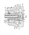
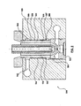
- FIG. 1 is a sectional view of a mold stack assembly according to an exemplary embodiment of the invention.
- a plurality of such mold stacks 100 are arranged within an injection molding system, in an array which corresponds to the number of preforms being molded during each injection molding cycle.
- Each mold stack 100 is concentric about a central axis 102.
- Mold stack 100 can be generally divided into a core assembly 104 and a cavity assembly 106, separable along a parting line P L , each of which are associated with a respective core half and cavity half of an injection molding system.
- Core assembly 104 and cavity assembly 106 cooperate to define a mold cavity 108 in which the molded article is formed.
- Core assembly 104 of mold stack 100 generally includes a mold core 110, a core support 112 and a split thread insert comprised of first half 114a and second half 114b.
- Mold core 110 is generally cylindrical and provides a cooling mechanism, such as a bubbler tube 116 in fluid communication with suitable supply/return cooling channels 118 provided in core plate 120.
- a cooling fluid is circulated through bubbler tube 116, so as to cool the temperature of mold core 110, thereby assisting in the solidification of the melt stream of moldable material injected into mold cavity 108.
- Split thread insert 114a/114b which provides the molding surface for the taper and thread region of the preform, also generally comprises a cooling mechanism.
- each half of the split thread insert 114a/114b may be provided with a cooling circuitry similar to that disclosed in US 5,599,567 .
- split thread insert 114a/114b is configured to be actuated by sliders or similar mechanism (not shown) mounted on a stripper plate (also not shown) to translate forwardly and/or laterally during preform ejection.
- Cavity assembly 106 of mold stack 100 generally includes a gate insert 122 and a cavity insert 124 located in series within a bore 126 extending through a cavity plate 128.
- the cavity assembly may also include an alignment ring 130 to assist in aligning the cavity assembly 106 to the core assembly 104.
- Gate insert 122 defines a mold gate 132 at the upstream end of the mold cavity 108. Downstream of mold gate 132, gate insert 122 defines a molding surface 134a, forming what is generally the terminal end of a molded preform article molded in mold cavity 108. Downstream face 136 of gate insert 122 is configured to engage the upstream face 138 of cavity insert 124, whereby gate insert 122 and cavity insert 124 concentrically align relative to central axis 102.
- Cavity insert 124 in cooperation with mold core 110 define the cylindrical body portion of mold cavity 108.
- the cavity insert 124 exemplified herein is generally defined by a body portion 140, and a flange portion 142.
- Body portion 140 of cavity insert 124 extends in a downstream direction perpendicular to upstream face 138 with flange portion 142 generally extending from said body portion 140.
- cavity insert 124 includes two cavity subcomponents, namely inner portion 146 and outer sleeve 148, where inner portion 146 is coaxially received by outer sleeve 148.
- the arrangement of inner portion 146 and outer sleeve 148 establishes a largely continuous annular cavity insert cooling chamber 144 therebetween, cavity insert cooling chamber 144 in fluid communication with corresponding cooling fluid supply/return channels, for example channel 150/151 provided in cavity plate 128.
- a cooling fluid is circulated through cavity insert cooling chamber 144 so as to cool the temperature of cavity insert 124, thereby assisting in the solidification of the melt stream of moldable material.
- inner portion 146 is provided with an outside surface 152 having an outer diameter that is less than the inner diameter of surface 154 of outer sleeve 148.
- Outer sleeve 148 is seated relative to the overall mold stack by virtue of its placement within the surrounding cavity plate 128.
- Inner portion 146 defines molding surface 134b, and is seated relative to the overall mold stack 100 by virtue of engagement with outer sleeve 148 at points P1 and P2.
- an outside contact surface 156 towards the upstream end of inner portion 146 is dimensioned to seat and engage an inside contact surface 158 of outer sleeve 148.
- Inner portion 146 is generally provided with suitable sealing features to ensure that cooling fluid is retained within cooling chamber 144. For example, as shown in FIG.
- an o-ring may be provided in a groove 160 situated on an end surface of inner portion 146, so as to provide a sealing effect when engaged with the adjacently positioned gate insert.
- the downstream region of inner portion 146 is provided with a flange 162 that seats within a corresponding bore 164 in outer sleeve 148.
- Flange 162 is also generally provided with suitable sealing features to ensure that cooling fluid is retained within cooling chamber 144.
- an o-ring may be provided in a groove 166 to ensure a sealed cooling chamber 144.
- Flange 162 further serves to axially locate alignment ring 130. Alignment ring 130 ensures proper axial alignment between the halves of split thread insert 114a/114b. and subsequently core assembly 104 and cavity assembly 106 of mold stack assembly 100, by way of interfaced tapers shown at T1/T2 (see FIG. 1 ).
- cooling of preforms in the vicinity of the neck/taper region is a difficult task with many mold stack configurations.
- cooling of the neck/tapered region is accomplished by way of the split thread insert.
- further enhancement of the cooling effect in the neck/tapered region is achieved by extending cooling chamber 144 along substantially the entire length of the cavity insert 124.
- outer sleeve 148 is provided with a chamber member 168 that positions within a corresponding recess 170 in the downstream portion of cavity insert 124 adjacent the split thread insert, for example in flange 162 of inner portion 146.
- Chamber member 168 is configured with outside surfaces 161a/161b being dimensionally smaller than the inside walls 163a/163b of corresponding recess 170 in flange 162, thereby defining a chamber extension connected in fluid communication to cooling chamber 144, through which cooling fluid is able to flow.
- the chamber extension is generally referred to as a hairpin chamber 172, having a generally annular hairpin or double-backed shaped configuration.
- cooling fluid that flows through cavity insert 124 is directed not only through the main cooling chamber 144 of the elongated body portion, but also through a first chamber extension portion 165a, a radial chamber extension portion 165b, and a second chamber extension portion 165c, thereby defining the annular loop structure of hairpin chamber 172 adjacent to the split thread insert.
- Cooling fluid flow may proceed in either direction through cooling chamber 144, depending on the configuration of the associated cooling fluid supply/return lines.
- a decompression chamber provided in fluid communication, and in relation to at least one end of cooling chamber 144 is a decompression chamber, the details of which are presented below.
- the decompression chamber is connected in fluid communication to at least the end of cooling chamber 144 representing the input side, that is the side where cooling fluid is entering cooling chamber 144.
- the cavity insert will have two decompression chambers, one connected in fluid communication to each end of cooling chamber 144, that is in relation to each of the input and output ends.
- cooling fluid may be configured to flow in either the upstream or downstream direction, depending on the configuration of the cooling fluid supply lines, and the manner of directing cooling fluid to respective cooling channels.
- cooling fluid flows in the downstream direction; that is in the same general direction as the melt flow through cavity 108.
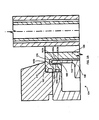
- the following explanation will also exemplify an arrangement where cooling fluid flows serially through gate insert 122 and cavity insert 124. Having regard to FIG. 2 , a flow of cooling fluid from a cooling channel 150 provided for in cavity plate 128 enters gate insert 122 through an inlet channel 176 which extends from the outside diameter of gate insert 122 to gate insert cooling chamber 178.
- Cooling chamber 178 circumscribes the gate insert molding surface and may generally correspond to the shape thereof, depending on the cooling circuit configuration chosen for gate insert 122. At a location generally diametrically opposite inlet channel 176 the flow of cooling fluid leaves cooling chamber 178 though outlet 182. On exit from gate insert 122, at outlet 182 cooling fluid then flows through a bridge channel 184 which fluidly connects gate insert 122 to cavity insert 124. From bridge channel 184, cooling fluid then flows through at least one radial cooling fluid channel 188 and enters into a first decompression chamber 186 between inner sleeve 146 and outer sleeve 148.
- First decompression chamber 186 is generally an annular channel on an inside surface of the outer sleeve, and is sized such that cooling fluid is able to substantially fill and encircle first decompression chamber 186 before flowing into a first end 187 of cooling chamber 144.
- Cooling chamber 144 extends substantially along the entire length of cavity insert l24 and has a cross-sectional area that is substantially smaller than that of first decompression chamber 186, such that in comparison with first decompression chamber 186, cooling chamber can be considered an annular compression cooling chamber. This relative difference in cross sectional area between first decompression chamber 186 and cooling chamber 144 promotes film flow of cooling fluid through cooling chamber 144, wherein substantially the entire annular chamber is in contact with a substantially uniform flow of cooling fluid.
- Second decompression chamber 190 is connected to fluidly communicate with return line 192 which allows cooling fluid to exit cavity insert 124 into a return line 151 provided in cavity plate 128.
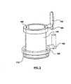
- FIG. 3 is a representation of the cooling fluid flow path defined by the above arrangement.
- the cooling fluid enters first decompression chamber 186 through radial cooling fluid channel 188, wherein by virtue of the compression differential with the downstream cooling chamber 144, the cooling fluid substantially fills first decompression chamber 186 and encircles the upstream portion of the cavity insert.
- the cooling fluid then proceeds to flow into cooling chamber 144, where the cooling flows along the length of cavity insert 124 in substantially film flow.
- film flow is defined as a generally uniform flow of cooling fluid in all regions of the cavity insert cooling chamber in the direction from the inlet, to the outlet.
- cooling fluid passes through hairpin chamber 172 and enters second decompression chamber 190. From second decompression chamber 190, the cooling fluid continues to flow through return line 192 back to cavity plate 128.
- An advantage of the largely continuous annular cavity insert cooling chamber arrangement described above is the overall wetting surface and uniformity of cooling fluid flow is increased when compared to prior art cavity inserts wherein the cooling chamber is comprised of a groove arranged on the outer surface of the insert through which a cooling fluid flows.
- cooling fluid is described as flowing in the downstream direction.
- second decompression chamber 190 provides the same functionality as first decompression chamber 186.
- second decompression chamber 190 serves to promote film flow through cavity chamber 144.
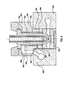
- FIG. 4 shown is another embodiment of cavity insert 424.
- the previous embodiment detailed in FIGS. 1 and 2 can be referenced for additional description of like parts, as only differences are discussed in detail below.
- Cavity assembly 406 includes a gate insert 422 and cavity insert 424 located in series within a bore 426 extending through a cavity plate 428.
- Cavity insert 424 is similar to cavity insert 124 described above, with one exception that cavity insert 424 excludes the hairpin channel feature.
- cavity insert cooling chamber 444 formed through the coaxial arrangement of inner portion 446 and outer sleeve 448, is connected to fluidly communicate directly with first decompression chamber 486 at first end 487, and second decompression chamber 490 at second end 489.
- the embodiment of FIG. 4 also provides a variation on the arrangement of first decompression chamber 486 and second decompression chamber 490 where these features are formed generally as an annular channel on the outer surface of the inner portion 446.
- the decompression chambers 486/490 are provided between inner portion 446 and outer sleeve 448.
- first decompression chamber 486 is connected in fluid communication with bridge channel 484 by way of radial cooling fluid channel 488.
- second decompression chamber 490 is connected so as to provide direct fluid communication with return line 492.
- the structural and functional characteristics of cavity insert 424 are the same as those described above for the embodiment shown in FIGS. 1 and 2 .
- FIG. 5 shown is another embodiment of cavity insert 524.
- the embodiment detailed in FIGS. 1 and 2 can be referenced for additional description of like parts, as only differences are discussed in detail below.
- Cavity assembly 506 includes a gate insert 522 and cavity insert 524 located in series within a bore 526 extending through a cavity plate 528.
- cavity insert 524 is a one-piece component comprised of a cavity insert body 529.
- cavity insert body 529 is configured to seat directly within mold plate 528, and by virtue of cavity insert body 529 having at least a portion of an outside surface 542 with an outer diameter that is less than the inner diameter of surface 554 of bore 526, cavity insert cooling chamber 544 is formed therebetween.
- Cavity insert cooling chamber 544 is connected to fluidly communicate directly with first decompression chamber 586 at a first end 587 and second decompression chamber 590 at a second end 589.
- First decompression chamber 586 and second decompression chamber 590 are generally provided as annular channels formed into bore 526 of cavity plate 528. As such, the decompression chambers 586/590 are provided between cavity insert 524 and mold plate 528. With this arrangement, that is with first decompression chamber 586 formed into bore 526 of cavity plate 528, first decompression chamber 586 is connected so as to fluidly communicate directly to bridge channel 584.
- second decompression chamber 590 is connected so as to fluidly communicate directly to return line 592.
- the structural and functional characteristics of cavity insert 524 are generally the same as those described above for the previous embodiments.
- FIG. 6 shown is another embodiment of cavity insert 624.
- the embodiment detailed in FIGS. 1 and 2 can be referenced for additional description of like parts, as only differences are discussed in detail below.
- Cavity assembly 606 includes a gate insert 622 and cavity insert 624 located in series within a bore 626 extending through a cavity plate 628.
- cavity insert 624 is a one-piece component comprised of a cavity insert body 629.
- cavity insert body 629 is configured to seat directly within mold plate 628, and by virtue of cavity insert body 629 having at least a portion of an outside surface 642 with an outer diameter that is less than the inner diameter of surface 654 of bore 626, cavity insert cooling chamber 644 is formed therebetween.
- Cavity insert cooling chamber 644 is connected to fluidly communicate directly with first decompression chamber 686 at first end 687 and second decompression chamber 690 at second end 689.
- first decompression chamber 686 and second decompression chamber 690 are generally provided as annular channels formed into an outside surface of cavity insert 624.
- the decompression chambers 686/690 are provided between cavity insert 624 and mold plate 628.
- first decompression chamber 686 is connected so as to fluidly communicate directly to bridge channel 684.
- second decompression chamber 690 is connected so as to fluidly communicate directly to return line 692.
- the structural and functional characteristics of cavity insert 624 are generally the same as those described above for the previous embodiments.
- FIG. 7 shown is a further embodiment of cavity insert 724 according to the present invention.
- the embodiment detailed in FIGS. 1 and 2 can be referenced for additional description of like parts, as only differences are discussed in detail below.
- Features and aspects described in other embodiments can be used accordingly with the present embodiment, and visa versa.
- Cavity assembly 706 includes a gate insert 722 and cavity insert 724 located in series within a bore 726 extending through a cavity plate 728.
- cavity insert 724 is a one-piece component comprised of a cavity insert body 729.
- cavity insert body 729 is configured to seat directly within mold plate 728, and by virtue of cavity insert body 729 having at least a portion of an outside surface 742 with an outer diameter that is less than the inner diameter of surface 754 of bore 726, cavity insert cooling chamber 744 is formed therebetween.
- Cavity insert cooling chamber 744 is connected to fluidly communicate with first decompression chamber 786 and second decompression chamber 790.
- first decompression chamber 786 is generally provided as an annular channel formed into bore 726 of cavity plate 728.
- Second decompression chamber 790 is provided as an annular channel on a downstream surface of cavity plate 728, at an interface between cavity plate 728 and cavity insert body 729.
- second decompression chamber 790 is connected so as to fluidly communicate to return line 792 which allows cooling fluid to exit cavity insert 724.
- the decompression chambers 786/790 are provided between cavity insert 724 and mold plate 728.
- the decompression chambers may alternatively be formed in the cavity insert, as shown in the embodiment detailed in FIG.
- FIG. 7 provides a hairpin chamber 772 similar to that provided in the embodiment of FIGS. 1 , 2 and 2A .
- cavity plate 728 is provided with a chamber member 768 that positions within a corresponding recess 770 in a downstream region of cavity insert body 729, for example flange 762.
- Chamber member 768 is configured to be dimensionally smaller than the corresponding recess 770 in flange 762, thereby defining a chamber extension connected in fluid communication to cooling chamber 744, through which cooling fluid is able to flow.
- the chamber extension is generally referred to as a hairpin chamber 772, having a generally annular hairpin or double-backed shaped configuration.
- cavity insert 724 cooling fluid that flows through cavity insert 724 is directed not only through the main cooling chamber 744 of the elongated body portion, but also the annular loop structure of hairpin chamber 772 adjacent to the split thread inserts.
- the structural and functional characteristics of cavity insert 724 are generally the same as those described above for the previous embodiments.
- Suitable material commonly used in injection molding devices.
- certain components may be made of conventional tool steel, stainless steel, or other suitable material that is able to withstand changes in temperature or thermal shock, which may occur as a result of the continuous cycling between extreme hot and cold temperatures.
- Thermally conductive materials may also be implemented where suitable.
- suitable materials for use in constructing the cavity insert include but are not limited to: copper and copper alloys, for example beryllium copper (MOLDMAX beryllium copper alloys, C 17000 alloys) and beryllium free copper (AMPCO 940, C18000), aluminum and aluminum alloys, molybdenum and molybdenum alloys (TZM).
- inner portion 146 and outer sleeve 148 may be permanently coupled, i.e., fixed or rigidly attached, such as by metallurgic bonding (e.g. brazing, soldering), or shrink fitting, or removably coupled, such as by press fitting.
Landscapes
- Engineering & Computer Science (AREA)
- Mechanical Engineering (AREA)
- Physics & Mathematics (AREA)
- Fluid Mechanics (AREA)
- Manufacturing & Machinery (AREA)
- Moulds For Moulding Plastics Or The Like (AREA)
Claims (15)
- Ensemble de moulage d'ébauche comprenant :une plaque de cavité (128, 728), etun insert de cavité (124, 724) que reçoit un alésage (126, 726) dans la plaque de cavité, l'insert de cavité (124, 724) étant destiné à former la partie du corps d'une ébauche,l'insert de cavité (124, 724) définissant au moins en partie un compartiment de refroidissement de l'insert de cavité (144, 744) etcaractérisé en ce que l'insert de cavité (124, 724) définit un compartiment de refroidissement annulaire à double face en U (172, 772) en communication par fluide avec le compartiment de refroidissement de l'insert de cavité (144, 744),le compartiment de refroidissement annulaire en U (172, 772) procurant un refroidissement à une extrémité en aval de l'insert de cavité (124, 724).
- Ensemble de moulage d'ébauche selon la revendication 1, dans lequel le compartiment de refroidissement de l'insert de cavité (744) et le compartiment de refroidissement annulaire en U (772) sont définis entre l'insert de cavité (724) et la plaque de cavité (728).
- Ensemble de moulage d'ébauche selon la revendication 2, dans lequel la plaque de cavité (728) comprend un élément formant compartiment (768) et l'insert de cavité comprend une partie formant flasque (762) qui définit un évidement permettant de recevoir l'élément formant compartiment (768), l'élément formant compartiment étant, en termes de dimensions, plus petit que l'évidement correspondant afin de définir ainsi le compartiment annulaire en U (772).
- Ensemble de moulage d'ébauche selon la revendication 1, dans lequel l'insert de cavité comprend une partie interne (146) et un manchon externe (148), et le compartiment de refroidissement de l'insert de cavité (144) ainsi que le compartiment de refroidissement annulaire en U (172) sont définis entre la partie interne (146) et le manchon externe (148).
- Ensemble de moulage d'ébauche selon la revendication 4, dans lequel le manchon externe (148) comprend un élément de compartiment (168), et l'insert de cavité (124) comprend une partie de flasque (162) qui définit un évidement permettant de recevoir l'élément de compartiment (168), l'élément de compartiment étant, en termes de dimensions, plus petit que l'évidement correspondant afin de définir ainsi le compartiment annulaire en U (172).
- Ensemble de moulage d'ébauche selon la revendication 3 et la revendication 5, dans lequel le compartiment annulaire en U (172) comprend une première partie d'extension de compartiment (165a) et une seconde partie d'extension de compartiment (165c) en communication par fluide avec la première partie d'extension de compartiment, l'élément de compartiment (168) étant placé entre la première partie d'extension de compartiment et la seconde partie d'extension de compartiment, grâce à quoi la circulation du fluide de refroidissement s'écoule depuis la première extension de compartiment jusqu'à la seconde extension de compartiment sur l'élément de compartiment.
- Ensemble de moulage d'ébauche selon l'une des revendications 1 à 6, dans lequel le compartiment de refroidissement de l'insert de cavité (144, 744) est un compartiment annulaire de refroidissement de l'insert de cavité.
- Ensemble de moulage d'ébauche selon la revendication 7, comprenant en outre un compartiment de décompression (186, 786) défini au moins en partie par l'insert de cavité (124, 724) en communication par fluide avec le compartiment annulaire de refroidissement de l'insert de cavité (144, 744).
- Ensemble de moulage d'ébauche selon la revendication 8, comprenant en outre un autre compartiment de décompression (190, 790) défini au moins en partie par l'insert de cavité (124, 724) en communication par fluide avec le compartiment annulaire de refroidissement en U (172, 772).
- Ensemble de moulage d'ébauche selon l'une des revendications 1 à 9, dans lequel l'extrémité en aval de l'insert de cavité est contiguë à une paire de filets de séparation (114a, 114b) qui procurent la surface de moulage à la zone de filets de l'ébauche.
- Procédé de mise en circulation d'un fluide de refroidissement afin de refroidir un insert de cavité (124, 724) destiné à former la partie du corps d'une ébauche, le procédé comprenant :l'écoulement du fluide de refroidissement le long d'une surface extérieure (152, 742) de l'insert de cavité (124, 724) afin de refroidir l'insert de cavité sur sa longueur,caractérisé par le rebroussement de l'écoulement du fluide de refroidissement au travers d'un compartiment de refroidissement annulaire en U (172, 772) à une extrémité en aval de l'insert de cavité afin de refroidir l'extrémité en aval de l'insert de cavité (124, 724)
- Procédé de mise en circulation d'un fluide de refroidissement afin de refroidir un insert de cavité (124, 724) destiné à former la partie du corps d'une ébauche selon la revendication 11, comprenant l'écoulement du fluide de refroidissement le long de la surface extérieure (152, 742) de l'insert de cavité afin de refroidir l'insert de cavité sur sa longueur avant de faire rebrousser l'écoulement du fluide de refroidissement au travers du compartiment de refroidissement annulaire en U (172, 772).
- Procédé de mise en circulation d'un fluide de refroidissement afin de refroidir un insert de cavité (124, 724) destiné à former la partie du corps d'une ébauche selon la revendication 11, comprenant l'écoulement du fluide de refroidissement le long de la surface extérieure (152, 742) de l'insert de cavité afin de refroidir l'insert de cavité sur sa longueur après avoir fait rebrousser l'écoulement du fluide de refroidissement au travers du compartiment de refroidissement annulaire en U (172, 772).
- Procédé de mise en circulation d'un fluide de refroidissement afin de refroidir un insert de cavité (124, 724) destiné à former la partie du corps d'une ébauche selon l'une des revendications 11 à 13, dans lequel l'écoulement du fluide de refroidissement le long de la surface extérieure (152, 742) de l'insert de cavité comprend la création d'un écoulement de pellicule annulaire du fluide de refroidissement.
- Procédé de mise en circulation d'un fluide de refroidissement afin de refroidir un insert de cavité (124, 724) destiné à former la partie du corps d'une ébauche selon l'une des revendications 13 et 14, comprenant en outre l'enveloppement de la partie de corps de l'ébauche avec l'écoulement du fluide de refroidissement avant écoulement au travers du compartiment de refroidissement annulaire en U (172, 772).
Applications Claiming Priority (1)
| Application Number | Priority Date | Filing Date | Title |
|---|---|---|---|
| US13/036,051 US9004906B2 (en) | 2011-02-28 | 2011-02-28 | Cavity insert film flow cooling |
Publications (2)
| Publication Number | Publication Date |
|---|---|
| EP2492079A1 EP2492079A1 (fr) | 2012-08-29 |
| EP2492079B1 true EP2492079B1 (fr) | 2014-05-14 |
Family
ID=45808150
Family Applications (2)
| Application Number | Title | Priority Date | Filing Date |
|---|---|---|---|
| EP20120001286 Not-in-force EP2492079B1 (fr) | 2011-02-28 | 2012-02-27 | Refroidissement d'insert de cavité de préforme |
| EP20120001287 Not-in-force EP2492080B1 (fr) | 2011-02-28 | 2012-02-27 | Refroidissement d'insert de cavité de préforme |
Family Applications After (1)
| Application Number | Title | Priority Date | Filing Date |
|---|---|---|---|
| EP20120001287 Not-in-force EP2492080B1 (fr) | 2011-02-28 | 2012-02-27 | Refroidissement d'insert de cavité de préforme |
Country Status (4)
| Country | Link |
|---|---|
| US (2) | US9004906B2 (fr) |
| EP (2) | EP2492079B1 (fr) |
| CN (2) | CN102729407B (fr) |
| CA (2) | CA2769954C (fr) |
Families Citing this family (14)
| Publication number | Priority date | Publication date | Assignee | Title |
|---|---|---|---|---|
| US9004906B2 (en) * | 2011-02-28 | 2015-04-14 | Mold-Masters (2007) Limited | Cavity insert film flow cooling |
| CN105050790B (zh) * | 2013-02-27 | 2017-04-05 | 赫斯基注塑系统有限公司 | 具有浮动腔插件的模具堆叠 |
| WO2015021536A1 (fr) * | 2013-08-16 | 2015-02-19 | Mold-Masters (2007) Limited | Ensemble cavité pour système de moulage d'une préforme |
| CA2923089C (fr) * | 2013-09-20 | 2017-12-05 | Husky Injection Molding Systems Ltd. | Composante de moule |
| US9616482B2 (en) * | 2013-11-05 | 2017-04-11 | Martinrea Industries, Inc. | Hot forming metal die with improved cooling system |
| CN104608327B (zh) * | 2014-12-30 | 2017-03-29 | 东泰精密模具(苏州)有限公司 | 一种用于生产带牙产品的模具 |
| EP3974403A1 (fr) * | 2016-05-30 | 2022-03-30 | FUJIFILM Corporation | Procédé de production d'un article moulé en phosphate de calcium, article moulé en phosphate de calcium et matériau pour transplantation |
| CN110382199B (zh) * | 2017-03-02 | 2021-09-24 | 日精Asb机械株式会社 | 成形用模具 |
| KR102586810B1 (ko) * | 2018-12-11 | 2023-10-10 | 허스키 인젝션 몰딩 시스템즈 리미티드 | 몰드, 몰드 조립체 및 스택 구성요소 |
| EP3894160A4 (fr) * | 2018-12-11 | 2022-09-07 | Husky Injection Molding Systems Luxembourg IP Development S.à.r.l | Moules, ensembles moules et éléments d'empilement |
| WO2020118413A1 (fr) | 2018-12-11 | 2020-06-18 | Husky Injection Molding Systems Ltd. | Moule d'injection dirigeant une charge de serrage à travers des empilements de moules |
| USD958209S1 (en) | 2019-06-04 | 2022-07-19 | Husky Injection Molding Systems Ltd. | Molding machine part |
| DE102019126939B4 (de) * | 2019-10-08 | 2022-02-10 | Lisa Dräxlmaier GmbH | Werkzeughälfte und verfahren zum herstellen eines spritzgussteils mit wenigstens einem bolzenartigen einlegeteil |
| US12544963B1 (en) * | 2025-09-05 | 2026-02-10 | Man Woo Heo | Multi-control system of mold cooling structure |
Family Cites Families (18)
| Publication number | Priority date | Publication date | Assignee | Title |
|---|---|---|---|---|
| US5423670A (en) | 1993-10-08 | 1995-06-13 | Hamel; Julio E. | Enhanced thermal transfer injection molding apparatus |
| CA2572585C (fr) | 1994-06-21 | 2009-11-24 | Jobst Ulrich Gellert | Entree et empreinte rapportee de moulage par injection |
| US5522448A (en) | 1994-09-27 | 1996-06-04 | Aluminum Company Of America | Cooling insert for casting mold and associated method |
| CA2160644C (fr) | 1995-10-16 | 2005-05-24 | Jobst Ulrich Gellert | Pieces rapportees fendues, filetees et refroidies pour preformes de moulage par injection |
| CA2262176C (fr) * | 1999-02-17 | 2008-04-22 | Jobst Ulrich Gellert | Element rapporte refroidi d'appareil de moulage par injection |
| JP2002052573A (ja) | 2000-08-07 | 2002-02-19 | Yazaki Corp | カセット式金型装置 |
| US7195223B2 (en) | 2002-12-02 | 2007-03-27 | Mark Manuel | System and a method for cooling a tool |
| ITRE20040127A1 (it) | 2004-10-12 | 2005-01-12 | Sacmi | Metodo e gruppo per la formatura a compressione di preforme per contenitori in materiale polimerico |
| US7361009B2 (en) * | 2005-10-20 | 2008-04-22 | Husky Injection Molding Systems Ltd. | Mold cavity insert for use in an injection mold |
| DE102006028174A1 (de) | 2006-06-16 | 2007-12-20 | Mht Mold & Hotrunner Technology Ag | Formnestkavität mit mäanderförmigem Kühlkanal |
| DE102006028149A1 (de) | 2006-06-16 | 2007-12-20 | Mht Mold & Hotrunner Technology Ag | Formnestkavität mit entkoppelter Kühlkanalführung |
| US7566216B2 (en) | 2007-04-29 | 2009-07-28 | Husky Injection Molding Systems Ltd. | Mold assembly using inserts |
| US7568906B2 (en) * | 2007-04-30 | 2009-08-04 | Husky Injection Molding Systems Ltd. | Mold assembly using inserts |
| US7575429B2 (en) | 2007-07-20 | 2009-08-18 | Husky Injection Molding Systems Ltd. | Compensating mold stack for use in a molding system |
| US7628605B2 (en) | 2007-07-20 | 2009-12-08 | Husky Injection Molding Systems Ltd. | Mold stack |
| US7645132B2 (en) | 2007-09-07 | 2010-01-12 | Husky Injection Molding Systems Ltd. | Mold insert and mold stack for use with molding machine |
| CA2755908C (fr) | 2009-04-24 | 2013-05-28 | Husky Injection Molding Systems Ltd. | Insert a cavite pour un systeme de moulage, l'insert a cavite ayant une partie deformable |
| US9004906B2 (en) * | 2011-02-28 | 2015-04-14 | Mold-Masters (2007) Limited | Cavity insert film flow cooling |
-
2011
- 2011-02-28 US US13/036,051 patent/US9004906B2/en not_active Expired - Fee Related
-
2012
- 2012-02-27 EP EP20120001286 patent/EP2492079B1/fr not_active Not-in-force
- 2012-02-27 EP EP20120001287 patent/EP2492080B1/fr not_active Not-in-force
- 2012-02-28 CN CN201210116099.2A patent/CN102729407B/zh not_active Expired - Fee Related
- 2012-02-28 CN CN201210116097.3A patent/CN102962949B/zh not_active Expired - Fee Related
- 2012-02-28 CA CA2769954A patent/CA2769954C/fr active Active
- 2012-02-28 CA CA2769958A patent/CA2769958C/fr active Active
-
2015
- 2015-03-05 US US14/639,584 patent/US9555559B2/en not_active Expired - Fee Related
Also Published As
| Publication number | Publication date |
|---|---|
| CA2769958C (fr) | 2019-02-19 |
| US9555559B2 (en) | 2017-01-31 |
| CA2769954A1 (fr) | 2012-08-28 |
| US20120219662A1 (en) | 2012-08-30 |
| US9004906B2 (en) | 2015-04-14 |
| EP2492080B1 (fr) | 2015-01-21 |
| EP2492079A1 (fr) | 2012-08-29 |
| CN102962949B (zh) | 2015-07-08 |
| EP2492080A1 (fr) | 2012-08-29 |
| US20150174792A1 (en) | 2015-06-25 |
| CA2769958A1 (fr) | 2012-08-28 |
| CN102962949A (zh) | 2013-03-13 |
| CA2769954C (fr) | 2019-02-26 |
| CN102729407B (zh) | 2015-06-17 |
| CN102729407A (zh) | 2012-10-17 |
Similar Documents
| Publication | Publication Date | Title |
|---|---|---|
| EP2492079B1 (fr) | Refroidissement d'insert de cavité de préforme | |
| CN105517772B (zh) | 模具组件 | |
| JP2002531297A (ja) | 螺旋溝を有する射出成形冷却コア | |
| EP3139024B1 (fr) | Procédé de production d'élément d'espacement de chemise d'eau | |
| US20160193769A1 (en) | Cavity Assembly for a Preform Molding System | |
| US10843424B2 (en) | Lens injection molded product to which hot runner is applied | |
| US20180345554A1 (en) | Cooling plate assembly for an injection molding machine | |
| CN111300752B (zh) | 模具、模具组件和堆叠部件 | |
| EP3590681B1 (fr) | Moule de moulage | |
| JPH10264208A (ja) | 冷却コアを有する射出成形装置 | |
| CN103442874A (zh) | 包括使每个进口与多个出口处于流体连通的一件式歧管组件的模具工具系统 | |
| CN105377525A (zh) | 注射成型方法和注射成型模具 | |
| CN108883560B (zh) | 注塑模具 | |
| JP2013540619A (ja) | マニホールドアセンブリ用の定温ヒーターアセンブリを備える金型工具アセンブリ | |
| EP3680084A1 (fr) | Moule | |
| JP2002307486A (ja) | 射出装置 | |
| JP2018008305A (ja) | 分流子 |
Legal Events
| Date | Code | Title | Description |
|---|---|---|---|
| PUAI | Public reference made under article 153(3) epc to a published international application that has entered the european phase |
Free format text: ORIGINAL CODE: 0009012 |
|
| AK | Designated contracting states |
Kind code of ref document: A1 Designated state(s): AL AT BE BG CH CY CZ DE DK EE ES FI FR GB GR HR HU IE IS IT LI LT LU LV MC MK MT NL NO PL PT RO RS SE SI SK SM TR |
|
| AX | Request for extension of the european patent |
Extension state: BA ME |
|
| 17P | Request for examination filed |
Effective date: 20130206 |
|
| GRAP | Despatch of communication of intention to grant a patent |
Free format text: ORIGINAL CODE: EPIDOSNIGR1 |
|
| RIC1 | Information provided on ipc code assigned before grant |
Ipc: B29C 45/73 20060101AFI20130517BHEP |
|
| INTG | Intention to grant announced |
Effective date: 20130604 |
|
| GRAP | Despatch of communication of intention to grant a patent |
Free format text: ORIGINAL CODE: EPIDOSNIGR1 |
|
| INTG | Intention to grant announced |
Effective date: 20131122 |
|
| GRAS | Grant fee paid |
Free format text: ORIGINAL CODE: EPIDOSNIGR3 |
|
| GRAA | (expected) grant |
Free format text: ORIGINAL CODE: 0009210 |
|
| AK | Designated contracting states |
Kind code of ref document: B1 Designated state(s): AL AT BE BG CH CY CZ DE DK EE ES FI FR GB GR HR HU IE IS IT LI LT LU LV MC MK MT NL NO PL PT RO RS SE SI SK SM TR |
|
| REG | Reference to a national code |
Ref country code: GB Ref legal event code: FG4D |
|
| REG | Reference to a national code |
Ref country code: CH Ref legal event code: NV Representative=s name: BOVARD AG, CH |
|
| REG | Reference to a national code |
Ref country code: AT Ref legal event code: REF Ref document number: 667909 Country of ref document: AT Kind code of ref document: T Effective date: 20140615 |
|
| REG | Reference to a national code |
Ref country code: IE Ref legal event code: FG4D |
|
| REG | Reference to a national code |
Ref country code: DE Ref legal event code: R096 Ref document number: 602012001588 Country of ref document: DE Effective date: 20140703 |
|
| REG | Reference to a national code |
Ref country code: NL Ref legal event code: VDEP Effective date: 20140514 Ref country code: AT Ref legal event code: MK05 Ref document number: 667909 Country of ref document: AT Kind code of ref document: T Effective date: 20140514 |
|
| REG | Reference to a national code |
Ref country code: LT Ref legal event code: MG4D |
|
| PG25 | Lapsed in a contracting state [announced via postgrant information from national office to epo] |
Ref country code: CY Free format text: LAPSE BECAUSE OF FAILURE TO SUBMIT A TRANSLATION OF THE DESCRIPTION OR TO PAY THE FEE WITHIN THE PRESCRIBED TIME-LIMIT Effective date: 20140514 Ref country code: IS Free format text: LAPSE BECAUSE OF FAILURE TO SUBMIT A TRANSLATION OF THE DESCRIPTION OR TO PAY THE FEE WITHIN THE PRESCRIBED TIME-LIMIT Effective date: 20140914 Ref country code: GR Free format text: LAPSE BECAUSE OF FAILURE TO SUBMIT A TRANSLATION OF THE DESCRIPTION OR TO PAY THE FEE WITHIN THE PRESCRIBED TIME-LIMIT Effective date: 20140815 Ref country code: NO Free format text: LAPSE BECAUSE OF FAILURE TO SUBMIT A TRANSLATION OF THE DESCRIPTION OR TO PAY THE FEE WITHIN THE PRESCRIBED TIME-LIMIT Effective date: 20140814 Ref country code: LT Free format text: LAPSE BECAUSE OF FAILURE TO SUBMIT A TRANSLATION OF THE DESCRIPTION OR TO PAY THE FEE WITHIN THE PRESCRIBED TIME-LIMIT Effective date: 20140514 Ref country code: FI Free format text: LAPSE BECAUSE OF FAILURE TO SUBMIT A TRANSLATION OF THE DESCRIPTION OR TO PAY THE FEE WITHIN THE PRESCRIBED TIME-LIMIT Effective date: 20140514 |
|
| PG25 | Lapsed in a contracting state [announced via postgrant information from national office to epo] |
Ref country code: HR Free format text: LAPSE BECAUSE OF FAILURE TO SUBMIT A TRANSLATION OF THE DESCRIPTION OR TO PAY THE FEE WITHIN THE PRESCRIBED TIME-LIMIT Effective date: 20140514 Ref country code: LV Free format text: LAPSE BECAUSE OF FAILURE TO SUBMIT A TRANSLATION OF THE DESCRIPTION OR TO PAY THE FEE WITHIN THE PRESCRIBED TIME-LIMIT Effective date: 20140514 Ref country code: SE Free format text: LAPSE BECAUSE OF FAILURE TO SUBMIT A TRANSLATION OF THE DESCRIPTION OR TO PAY THE FEE WITHIN THE PRESCRIBED TIME-LIMIT Effective date: 20140514 Ref country code: RS Free format text: LAPSE BECAUSE OF FAILURE TO SUBMIT A TRANSLATION OF THE DESCRIPTION OR TO PAY THE FEE WITHIN THE PRESCRIBED TIME-LIMIT Effective date: 20140514 Ref country code: ES Free format text: LAPSE BECAUSE OF FAILURE TO SUBMIT A TRANSLATION OF THE DESCRIPTION OR TO PAY THE FEE WITHIN THE PRESCRIBED TIME-LIMIT Effective date: 20140514 Ref country code: PL Free format text: LAPSE BECAUSE OF FAILURE TO SUBMIT A TRANSLATION OF THE DESCRIPTION OR TO PAY THE FEE WITHIN THE PRESCRIBED TIME-LIMIT Effective date: 20140514 Ref country code: AT Free format text: LAPSE BECAUSE OF FAILURE TO SUBMIT A TRANSLATION OF THE DESCRIPTION OR TO PAY THE FEE WITHIN THE PRESCRIBED TIME-LIMIT Effective date: 20140514 |
|
| PG25 | Lapsed in a contracting state [announced via postgrant information from national office to epo] |
Ref country code: PT Free format text: LAPSE BECAUSE OF FAILURE TO SUBMIT A TRANSLATION OF THE DESCRIPTION OR TO PAY THE FEE WITHIN THE PRESCRIBED TIME-LIMIT Effective date: 20140915 |
|
| PG25 | Lapsed in a contracting state [announced via postgrant information from national office to epo] |
Ref country code: RO Free format text: LAPSE BECAUSE OF FAILURE TO SUBMIT A TRANSLATION OF THE DESCRIPTION OR TO PAY THE FEE WITHIN THE PRESCRIBED TIME-LIMIT Effective date: 20140514 Ref country code: DK Free format text: LAPSE BECAUSE OF FAILURE TO SUBMIT A TRANSLATION OF THE DESCRIPTION OR TO PAY THE FEE WITHIN THE PRESCRIBED TIME-LIMIT Effective date: 20140514 Ref country code: EE Free format text: LAPSE BECAUSE OF FAILURE TO SUBMIT A TRANSLATION OF THE DESCRIPTION OR TO PAY THE FEE WITHIN THE PRESCRIBED TIME-LIMIT Effective date: 20140514 Ref country code: CZ Free format text: LAPSE BECAUSE OF FAILURE TO SUBMIT A TRANSLATION OF THE DESCRIPTION OR TO PAY THE FEE WITHIN THE PRESCRIBED TIME-LIMIT Effective date: 20140514 Ref country code: BE Free format text: LAPSE BECAUSE OF FAILURE TO SUBMIT A TRANSLATION OF THE DESCRIPTION OR TO PAY THE FEE WITHIN THE PRESCRIBED TIME-LIMIT Effective date: 20140514 Ref country code: SK Free format text: LAPSE BECAUSE OF FAILURE TO SUBMIT A TRANSLATION OF THE DESCRIPTION OR TO PAY THE FEE WITHIN THE PRESCRIBED TIME-LIMIT Effective date: 20140514 |
|
| REG | Reference to a national code |
Ref country code: DE Ref legal event code: R097 Ref document number: 602012001588 Country of ref document: DE |
|
| PG25 | Lapsed in a contracting state [announced via postgrant information from national office to epo] |
Ref country code: NL Free format text: LAPSE BECAUSE OF FAILURE TO SUBMIT A TRANSLATION OF THE DESCRIPTION OR TO PAY THE FEE WITHIN THE PRESCRIBED TIME-LIMIT Effective date: 20140514 |
|
| PLBE | No opposition filed within time limit |
Free format text: ORIGINAL CODE: 0009261 |
|
| STAA | Information on the status of an ep patent application or granted ep patent |
Free format text: STATUS: NO OPPOSITION FILED WITHIN TIME LIMIT |
|
| 26N | No opposition filed |
Effective date: 20150217 |
|
| REG | Reference to a national code |
Ref country code: DE Ref legal event code: R097 Ref document number: 602012001588 Country of ref document: DE Effective date: 20150217 |
|
| PG25 | Lapsed in a contracting state [announced via postgrant information from national office to epo] |
Ref country code: SI Free format text: LAPSE BECAUSE OF FAILURE TO SUBMIT A TRANSLATION OF THE DESCRIPTION OR TO PAY THE FEE WITHIN THE PRESCRIBED TIME-LIMIT Effective date: 20140514 |
|
| PG25 | Lapsed in a contracting state [announced via postgrant information from national office to epo] |
Ref country code: MC Free format text: LAPSE BECAUSE OF FAILURE TO SUBMIT A TRANSLATION OF THE DESCRIPTION OR TO PAY THE FEE WITHIN THE PRESCRIBED TIME-LIMIT Effective date: 20140514 |
|
| REG | Reference to a national code |
Ref country code: IE Ref legal event code: MM4A |
|
| REG | Reference to a national code |
Ref country code: FR Ref legal event code: ST Effective date: 20151030 |
|
| PG25 | Lapsed in a contracting state [announced via postgrant information from national office to epo] |
Ref country code: IE Free format text: LAPSE BECAUSE OF NON-PAYMENT OF DUE FEES Effective date: 20150227 |
|
| PG25 | Lapsed in a contracting state [announced via postgrant information from national office to epo] |
Ref country code: FR Free format text: LAPSE BECAUSE OF NON-PAYMENT OF DUE FEES Effective date: 20150302 |
|
| GBPC | Gb: european patent ceased through non-payment of renewal fee |
Effective date: 20160227 |
|
| PG25 | Lapsed in a contracting state [announced via postgrant information from national office to epo] |
Ref country code: MT Free format text: LAPSE BECAUSE OF FAILURE TO SUBMIT A TRANSLATION OF THE DESCRIPTION OR TO PAY THE FEE WITHIN THE PRESCRIBED TIME-LIMIT Effective date: 20140514 |
|
| PG25 | Lapsed in a contracting state [announced via postgrant information from national office to epo] |
Ref country code: GB Free format text: LAPSE BECAUSE OF NON-PAYMENT OF DUE FEES Effective date: 20160227 |
|
| PG25 | Lapsed in a contracting state [announced via postgrant information from national office to epo] |
Ref country code: BG Free format text: LAPSE BECAUSE OF FAILURE TO SUBMIT A TRANSLATION OF THE DESCRIPTION OR TO PAY THE FEE WITHIN THE PRESCRIBED TIME-LIMIT Effective date: 20140514 Ref country code: SM Free format text: LAPSE BECAUSE OF FAILURE TO SUBMIT A TRANSLATION OF THE DESCRIPTION OR TO PAY THE FEE WITHIN THE PRESCRIBED TIME-LIMIT Effective date: 20140514 Ref country code: HU Free format text: LAPSE BECAUSE OF FAILURE TO SUBMIT A TRANSLATION OF THE DESCRIPTION OR TO PAY THE FEE WITHIN THE PRESCRIBED TIME-LIMIT; INVALID AB INITIO Effective date: 20120227 |
|
| PG25 | Lapsed in a contracting state [announced via postgrant information from national office to epo] |
Ref country code: TR Free format text: LAPSE BECAUSE OF FAILURE TO SUBMIT A TRANSLATION OF THE DESCRIPTION OR TO PAY THE FEE WITHIN THE PRESCRIBED TIME-LIMIT Effective date: 20140514 |
|
| PG25 | Lapsed in a contracting state [announced via postgrant information from national office to epo] |
Ref country code: MK Free format text: LAPSE BECAUSE OF FAILURE TO SUBMIT A TRANSLATION OF THE DESCRIPTION OR TO PAY THE FEE WITHIN THE PRESCRIBED TIME-LIMIT Effective date: 20140514 |
|
| PG25 | Lapsed in a contracting state [announced via postgrant information from national office to epo] |
Ref country code: AL Free format text: LAPSE BECAUSE OF FAILURE TO SUBMIT A TRANSLATION OF THE DESCRIPTION OR TO PAY THE FEE WITHIN THE PRESCRIBED TIME-LIMIT Effective date: 20140514 |
|
| PGFP | Annual fee paid to national office [announced via postgrant information from national office to epo] |
Ref country code: LU Payment date: 20220119 Year of fee payment: 11 |
|
| PGFP | Annual fee paid to national office [announced via postgrant information from national office to epo] |
Ref country code: DE Payment date: 20220119 Year of fee payment: 11 Ref country code: CH Payment date: 20220120 Year of fee payment: 11 |
|
| PGFP | Annual fee paid to national office [announced via postgrant information from national office to epo] |
Ref country code: IT Payment date: 20220119 Year of fee payment: 11 |
|
| REG | Reference to a national code |
Ref country code: DE Ref legal event code: R119 Ref document number: 602012001588 Country of ref document: DE |
|
| REG | Reference to a national code |
Ref country code: CH Ref legal event code: PL |
|
| PG25 | Lapsed in a contracting state [announced via postgrant information from national office to epo] |
Ref country code: LU Free format text: LAPSE BECAUSE OF NON-PAYMENT OF DUE FEES Effective date: 20230227 Ref country code: LI Free format text: LAPSE BECAUSE OF NON-PAYMENT OF DUE FEES Effective date: 20230228 Ref country code: CH Free format text: LAPSE BECAUSE OF NON-PAYMENT OF DUE FEES Effective date: 20230228 |
|
| PG25 | Lapsed in a contracting state [announced via postgrant information from national office to epo] |
Ref country code: IT Free format text: LAPSE BECAUSE OF NON-PAYMENT OF DUE FEES Effective date: 20230227 Ref country code: DE Free format text: LAPSE BECAUSE OF NON-PAYMENT OF DUE FEES Effective date: 20230901 |