EP2492130A2 - Appareil à pédale d'accélérateur - Google Patents
Appareil à pédale d'accélérateur Download PDFInfo
- Publication number
- EP2492130A2 EP2492130A2 EP12156472A EP12156472A EP2492130A2 EP 2492130 A2 EP2492130 A2 EP 2492130A2 EP 12156472 A EP12156472 A EP 12156472A EP 12156472 A EP12156472 A EP 12156472A EP 2492130 A2 EP2492130 A2 EP 2492130A2
- Authority
- EP
- European Patent Office
- Prior art keywords
- accelerator pedal
- reaction force
- force
- adding mechanism
- pedaling
- Prior art date
- Legal status (The legal status is an assumption and is not a legal conclusion. Google has not performed a legal analysis and makes no representation as to the accuracy of the status listed.)
- Granted
Links
Images




Classifications
-
- B—PERFORMING OPERATIONS; TRANSPORTING
- B60—VEHICLES IN GENERAL
- B60T—VEHICLE BRAKE CONTROL SYSTEMS OR PARTS THEREOF; BRAKE CONTROL SYSTEMS OR PARTS THEREOF, IN GENERAL; ARRANGEMENT OF BRAKING ELEMENTS ON VEHICLES IN GENERAL; PORTABLE DEVICES FOR PREVENTING UNWANTED MOVEMENT OF VEHICLES; VEHICLE MODIFICATIONS TO FACILITATE COOLING OF BRAKES
- B60T7/00—Brake-action initiating means
- B60T7/12—Brake-action initiating means for automatic initiation; for initiation not subject to will of driver or passenger
- B60T7/22—Brake-action initiating means for automatic initiation; for initiation not subject to will of driver or passenger initiated by contact of vehicle, e.g. bumper, with an external object, e.g. another vehicle, or by means of contactless obstacle detectors mounted on the vehicle
-
- B—PERFORMING OPERATIONS; TRANSPORTING
- B60—VEHICLES IN GENERAL
- B60K—ARRANGEMENT OR MOUNTING OF PROPULSION UNITS OR OF TRANSMISSIONS IN VEHICLES; ARRANGEMENT OR MOUNTING OF PLURAL DIVERSE PRIME-MOVERS IN VEHICLES; AUXILIARY DRIVES FOR VEHICLES; INSTRUMENTATION OR DASHBOARDS FOR VEHICLES; ARRANGEMENTS IN CONNECTION WITH COOLING, AIR INTAKE, GAS EXHAUST OR FUEL SUPPLY OF PROPULSION UNITS IN VEHICLES
- B60K26/00—Arrangement or mounting of propulsion-unit control devices in vehicles
- B60K26/02—Arrangement or mounting of propulsion-unit control devices in vehicles of initiating means or elements
- B60K26/021—Arrangement or mounting of propulsion-unit control devices in vehicles of initiating means or elements with means for providing feel, e.g. by changing pedal force characteristics
-
- B—PERFORMING OPERATIONS; TRANSPORTING
- B60—VEHICLES IN GENERAL
- B60T—VEHICLE BRAKE CONTROL SYSTEMS OR PARTS THEREOF; BRAKE CONTROL SYSTEMS OR PARTS THEREOF, IN GENERAL; ARRANGEMENT OF BRAKING ELEMENTS ON VEHICLES IN GENERAL; PORTABLE DEVICES FOR PREVENTING UNWANTED MOVEMENT OF VEHICLES; VEHICLE MODIFICATIONS TO FACILITATE COOLING OF BRAKES
- B60T8/00—Arrangements for adjusting wheel-braking force to meet varying vehicular or ground-surface conditions, e.g. limiting or varying distribution of braking force
- B60T8/17—Using electrical or electronic regulation means to control braking
- B60T8/172—Determining control parameters used in the regulation, e.g. by calculations involving measured or detected parameters
-
- B—PERFORMING OPERATIONS; TRANSPORTING
- B60—VEHICLES IN GENERAL
- B60W—CONJOINT CONTROL OF VEHICLE SUB-UNITS OF DIFFERENT TYPE OR DIFFERENT FUNCTION; CONTROL SYSTEMS SPECIALLY ADAPTED FOR HYBRID VEHICLES; ROAD VEHICLE DRIVE CONTROL SYSTEMS FOR PURPOSES NOT RELATED TO THE CONTROL OF A PARTICULAR SUB-UNIT
- B60W10/00—Conjoint control of vehicle sub-units of different type or different function
- B60W10/18—Conjoint control of vehicle sub-units of different type or different function including control of braking systems
-
- G—PHYSICS
- G05—CONTROLLING; REGULATING
- G05G—CONTROL DEVICES OR SYSTEMS INSOFAR AS CHARACTERISED BY MECHANICAL FEATURES ONLY
- G05G5/00—Means for preventing, limiting or returning the movements of parts of a control mechanism, e.g. locking controlling member
- G05G5/03—Means for enhancing the operator's awareness of arrival of the controlling member at a command or datum position; Providing feel, e.g. means for creating a counterforce
-
- B—PERFORMING OPERATIONS; TRANSPORTING
- B60—VEHICLES IN GENERAL
- B60K—ARRANGEMENT OR MOUNTING OF PROPULSION UNITS OR OF TRANSMISSIONS IN VEHICLES; ARRANGEMENT OR MOUNTING OF PLURAL DIVERSE PRIME-MOVERS IN VEHICLES; AUXILIARY DRIVES FOR VEHICLES; INSTRUMENTATION OR DASHBOARDS FOR VEHICLES; ARRANGEMENTS IN CONNECTION WITH COOLING, AIR INTAKE, GAS EXHAUST OR FUEL SUPPLY OF PROPULSION UNITS IN VEHICLES
- B60K26/00—Arrangement or mounting of propulsion-unit control devices in vehicles
- B60K26/02—Arrangement or mounting of propulsion-unit control devices in vehicles of initiating means or elements
- B60K26/021—Arrangement or mounting of propulsion-unit control devices in vehicles of initiating means or elements with means for providing feel, e.g. by changing pedal force characteristics
- B60K2026/023—Arrangement or mounting of propulsion-unit control devices in vehicles of initiating means or elements with means for providing feel, e.g. by changing pedal force characteristics with electrical means to generate counter force or torque
-
- G—PHYSICS
- G05—CONTROLLING; REGULATING
- G05G—CONTROL DEVICES OR SYSTEMS INSOFAR AS CHARACTERISED BY MECHANICAL FEATURES ONLY
- G05G1/00—Controlling members, e.g. knobs or handles; Assemblies or arrangements thereof; Indicating position of controlling members
- G05G1/30—Controlling members actuated by foot
- G05G1/44—Controlling members actuated by foot pivoting
Definitions
- the present invention relates to an accelerator pedal apparatus applied to vehicles and the like having a drive-by-wire system, and in particular, relates to an accelerator pedal apparatus including a reaction force generating mechanism which generates reaction force (i.e. push-back force) against pedaling force of a pedal arm for danger avoidance, danger notification or the like.
- a reaction force generating mechanism which generates reaction force (i.e. push-back force) against pedaling force of a pedal arm for danger avoidance, danger notification or the like.
- an accelerator pedal apparatus including a hysteresis generating mechanism to provide a hysteresis characteristic to relation between a stroke (i.e. , a depression amount) and pedaling force of an accelerator pedal as pedaling force during return operation is to be smaller than pedaling force during depression operation is applied to an electronically controlled throttle system (i.e., a drive-by-wire system).
- a stroke i.e. , a depression amount
- pedaling force of an accelerator pedal as pedaling force during return operation is to be smaller than pedaling force during depression operation
- an electronically controlled throttle system i.e., a drive-by-wire system
- an accelerator pedal apparatus including pedaling force change means (i.e., a reaction force adding mechanism) which appropriately adds reaction force to pedaling force at the depression side of the accelerator pedal to obtain appropriate pedaling force in accordance with vehicle drive states while maintaining an initially-set characteristic pedaling force at the return side of the accelerator pedal regardless of the vehicle drive states (for example, see Japanese Patent Laid-open 2004-314871 ).
- pedaling force change means i.e., a reaction force adding mechanism
- examples of a case to suppress depression by adding reaction force during depression operation of an accelerator pedal includes a case to improve fuel consumption by suppressing excessive depression, a case to notify of getting closer to a vehicle in front during driving, and a case to require avoidance or notification of other danger.
- the above cases are not limited only to during depression operation of the accelerator pedal. Even during return operation of the accelerator pedal, there is a fear such that danger cannot be avoided as getting excessively closer to a vehicle in front or that smooth driving cannot be performed when the return amount is insufficient or the return operation is slow.
- the present invention provides an accelerator pedal apparatus of which pedaling force has a hysteresis characteristic, the apparatus being capable of quickly performing danger avoidance or danger notification during operation (i.e., depression operation and return operation) of an accelerator pedal and being capable of preventing to provide a feeling of strangeness to a driver when reaction force is added.
- An accelerator pedal apparatus of the present invention includes an accelerator pedal, a hysteresis generating mechanism which generates hysteresis on pedaling force of the accelerator pedal, a reaction force adding mechanism which adds reaction force to push back the accelerator pedal toward a rest position, and control means which performs drive control of the reaction force adding mechanism, while the control means performs drive control of the reaction force adding mechanism so that reaction force is added during depressing of the accelerator pedal under predetermined conditions and reaction force is added during returning of the accelerator pedal under predetermined conditions as the reaction force being larger than pedaling force difference between pedaling force at the depression side and pedaling force at the return side of the pedaling force hysteresis.
- the pedaling force follows a characteristic line at the return side of the hysteresis characteristic to which reaction force is added regardless of being during depression operation as the accelerator pedal being slightly returned by the reaction force.
- the pedaling force becomes smaller than pedaling force at the depression side to which reaction force is not added at an accelerator opening (i.e., an accelerator stroke), that is, the pedaling force characteristic line having reaction force added and the pedaling force characteristic line having reaction force not added are partially overlapped.
- the control means may perform drive control of the reaction force adding mechanism so that reaction force to be added during depressing of the accelerator pedal is larger than reaction force to be added during returning of the accelerator pedal.
- the pedaling force follows the characteristic line at the return side of the hysteresis characteristic to which reaction force is added regardless of being during depression operation as the accelerator pedal being slightly returned by the reaction force.
- the reaction force to be added during depression operation is equal to the reaction force to be added during return operation, it is difficult for a driver to recognize the added reaction force.
- reaction force being larger than the reaction force to be added during return operation of the accelerator pedal is added during depression operation, the reaction force can be reliably felt during depression operation by the driver. Further, appropriate accelerator feeling can be actualized without providing a feeling of strangeness to the driver.
- control means may determine after the reaction force is added whether or not reaction force is to be further added based on operational information of the accelerator pedal. According to the above structure, when the accelerator pedal is operated to be returned after the reaction force is added, reaction force is not to be further added. In contrast, when the accelerator pedal is further depressed even after the reaction force is added, reaction force is to be further added. Accordingly, it is possible to sufficiently perform danger avoidance or to continuously perform danger notification.
- the reaction force adding mechanism may include a torque motor which exerts rotational torque to push back the accelerator pedal as being engaged therewith, and the control means may appropriately set reaction force magnitude by adjusting drive current of the torque motor.
- the torque motor since the torque motor is adopted for the reaction force adding mechanism, reaction force can be added with a simple control method while achieving structural simplification and the like.
- the above structure may further include detection means which detects operation of the accelerator pedal, and then, the control means may determine based on output information of the detection means whether the accelerator pedal is in depression operation or return operation and may perform drive control of the reaction force adding mechanism.
- operation of the accelerator pedal is determined whether being depression operation or being return operation based on the detection information of the detection means, and then, reaction force adding is performed by the reaction force adding mechanism based on the determination result. Therefore, operation of the accelerator pedal can be directly reflected to reaction force adding control, so that reaction force can be accurately added at desired timing respectively during depression operation and return operation of the accelerator pedal.
- the above structure may further include drive state detection means which detects a vehicle drive state or an engine drive state, and the control means may perform drive control of the reaction force adding mechanism based on detection information of the drive state detection means.
- drive control of the reaction force adding mechanism is appropriately performed based on the various drive information (such as vehicle speed, engine speed, distance against a vehicle in front, road surface information and a drive mode) detected by the drive state detection means, it is possible that danger avoidance and danger notification are quickly performed in an appropriate state and that fuel consumption is reduced without providing a feeling of strangeness to a driver.
- the accelerator pedal apparatus with the above structure having a hysteresis characteristic on pedaling force, it is possible to quickly perform danger avoidance or danger notification during operation (i.e., depression operation and return operation) of an accelerator pedal and to prevent to provide a feeling of strangeness to a driver when reaction force is added.
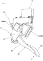
- an accelerator pedal apparatus of an embodiment includes a housing 10 fixed to a vehicle of an automobile and the like, an accelerator pedal 20 supported swingably about a predetermined axis line L1, a return spring 30 which exerts urging force to return the accelerator pedal 20 toward a rest position, a hysteresis generating mechanism 40 which generates hysteresis on pedaling force (i.e., a pedal load) while exerting urging force to return the accelerator pedal 20 toward the rest position, an accelerator position sensor (APS) 50 as detection means to detect a rotational angle position and a rotational direction of the accelerator pedal 20, a reaction force adding mechanism 60 which generates reaction force to return the accelerator pedal 20 toward the rest position under predetermined conditions, a control system 70 as control means to perform drive control of the reaction force adding mechanism 60, and the like.
- APS accelerator position sensor
- the hysteresis generating mechanism 40 includes a first slider 41, a second slider 42, a return spring 43, and the like.
- the reaction force adding mechanism 60 includes a torque motor 61, a return lever 62, a motor position sensor (MPS) 63, and the like.
- the housing 10 being formed of resin as a whole supports the accelerator pedal 20 swingably about an axis line L1, as illustrated in FIGS. 1 to 3 .
- the return spring 30 and the hysteresis generating mechanism 40 are accommodated, the accelerator position sensor 50 is embedded around the axis line L1, and a later-mentioned control unit 71 which performs electric connection with the outside is embedded at an upper area thereof.
- the accelerator pedal 20 being formed of resin as a whole includes a cylindrical portion 21 rotatably supported by a support shaft 10a of the housing 10, a lower arm portion 22 integrally formed as being extended downward from the cylindrical portion 21, an upper arm portion 23 integrally formed as being extended upward from the cylindrical portion 21, a pedal portion 24 integrally formed with the lower arm portion 22, and the like, as illustrated in FIGS. 1 to 3 .
- the upper arm portion 23 is formed to be engaged with a part (i.e., the first slider 41) of the hysteresis generating mechanism 40 and a part (i.e., the return lever 62) of the reaction force adding mechanism 60.
- the return spring 30 is a compression type coil spring formed of spring steel and the like. As illustrated in FIG. 3 , the return spring 30 is arranged in a state of being compressed to have a predetermined compression amount as one end part thereof being engaged with an inner wall of the housing 10 and the other end part thereof being engaged with a part of the accelerator pedal 20 (i.e., the upper arm portion 23). In this manner, the return spring 30 exerts urging force to the accelerator pedal 20 to return toward the rest position.
- the hysteresis generating mechanism 40 including the first slider 41, the second slider 42 and the return spring 43 which are accommodated in the housing 10 is structured to generate hysteresis on the pedaling force (i.e., the pedal load) as being engaged with an upper end part of the upper arm portion 23 of the accelerator pedal 20 in a disengageable manner.
- the first slider 41 is formed of resin material (e.g., high slidability material such as oil-bearing polyacetal). As illustrated in FIG.
- the first slider 41 slidably contacts to a lower inner wall face 10b of the housing 10 and includes an inclined face contacting to an inclined face of the second slider 42, an engaging face with which the upper end part of the upper arm portion 23 can be engaged in a disengageable manner, and the like.
- the second slider 42 is formed of resin material (e.g., high slidability material such as oil-bearing polyacetal). As illustrated in FIG. 3 , the second slider 42 slidably contacts to an upper inner wall face 10c of the housing 10 and includes the inclined face contacting to the inclined face of the first slider 41, a receiving face which receives one end part of the return spring 43, and the like.
- the return spring 43 is a compression type coil spring formed of spring steel and the like.
- the return spring 43 is arranged in a state of being compressed to have a predetermined compression amount as one end part thereof being engaged with the receiving face of the second slider 42 and the other end part thereof being engaged with an inner wall of the housing 10. In this manner, the return spring 43 pushes the inclined face of the second slider 42 to the inclined face of the first slider 41 so as to exert urging force to return the accelerator pedal 20 toward the rest position via the first slider 41 and the second slider 42 while exerting a wedge effect to push the first slider 41 and the second slider 42 respectively toward the lower inner wall face 10b and the upper inner wall face 10c.
- the accelerator position sensor (APS) 50 is arranged at the cylindrical portion 21 of the accelerator pedal 20 and a sensor accommodating portion of the housing 10.
- the accelerator position sensor 50 is a non-contact type magnetic sensor, for example, and is provided with a circular armature made of magnetic material arranged at the area of the cylindrical portion 21 of the accelerator pedal 20, a pair of arc-shaped permanent magnets connected to an inner circumferential face of the armature, two stators made of magnetic material embedded in the housing 10, two Hall elements arranged between the two stators, and the like.
- a circuit board having terminals and various electric components mounted is provided as a component relating thereto.
- the accelerator position sensor 50 detects variation of magnetic flux density with the Hall elements and outputs as a voltage signal. Then, the accelerator pedal 20 is detected whether being in the depression operation or in the return operation based on a variation amount of the voltage signal while detecting the angle position of the accelerator pedal 20.
- the reaction force adding mechanism 60 is provided with the torque motor 61 which is accommodated in the housing 10, the return lever 62 which is engaged with the upper arm portion 23 of the accelerator pedal 20 in a disengageable manner as being directly connected to the torque motor 61, the motor position sensor (MPS) 63 which detects a rotational angle of the return lever 62 as being accommodated in a sensor accommodating portion of the housing 10, and the like.
- the torque motor 61 integrally rotates the directly-connected return lever 62 about the axis line L2 within a predetermined angle range in a reciprocated manner.
- the torque motor 61 is adopted as a drive source.
- any drive source having another structure may be adopted as long as being capable of rotating the return lever 62 against pedaling force of the accelerator pedal 20.
- the return lever 62 is formed so that the top end part thereof is engaged with the upper arm portion 23 of the accelerator pedal 20 in a disengageable manner as being directly connected to a rotation shaft of the torque motor 61 rotating about the axis line L2.
- drive force i.e., rotational torque
- the return lever 62 is freely rotated to follow swinging of the accelerator pedal 20, that is, to follow without exerting resistant force to movement of the upper arm portion 23.
- the return lever 62 exerts reaction force to the upper arm portion 23 to push back the accelerator pedal 20 toward the rest position against the pedaling force.
- the motor position sensor (MPS) 63 is arranged at the sensor accommodating portion of the housing 10 to detect an angle position of the torque motor 61, that is, an angle position of the return lever 62.
- the motor position sensor (MPS) 63 may adopt a contact-type or non-contact type sensor.
- the reaction force adding mechanism 60 is structured with the torque motor 61, the return lever 62 and the motor position sensor 63, simplification of the reaction force adding mechanism 60 and miniaturization of the apparatus can be achieved and response can be improved in a case that control to add reaction force is required in predetermined conditions.
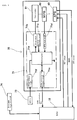
- the control system 70 includes a control unit 71 embedded in the housing 10, an ECU 72 which performs overall control as being mounted on a vehicle, a battery 73 mounted on the vehicle, a drive state detection circuit 74 as drive state detection means which detects various drive states of the vehicle or an engine, and the like.
- the control unit 70 is embedded at an upper area of the housing 10 and is provided with a microcomputer (i.e., a chip) 71a which performs control, a drive circuit 71b which drives the torque motor 61 based on a control signal of the microcomputer 71a, a current detection circuit 71c which detects drive current to drive the torque motor 61, an MPS input circuit 71d which transmits a detection signal of the motor position sensor (MPS) 63, an interface circuit 71e which performs transmitting and receiving of signals (i.e., data) between the microcomputer 71a and the ECU 72 owing to controller area network (CAN) communication, and a power source circuit 71f which supplies power to the microcomputer 71a.
- a microcomputer i.e., a chip
- the accelerator position sensor (APS) 50 is connected to the ECU 72 to transmit the detection signal thereto.
- the drive state detection circuit 74 detects various drive information such as vehicle speed, engine speed, distance against a vehicle in front, road surface information and a drive mode.
- the reaction force adding mechanism 60 is controlled to be appropriately driven via the ECU 72 and the control unit 71 so that danger avoidance and danger notification are quickly performed in an appropriate state without providing a feeling of strangeness to a driver, and further, that fuel consumption is reduced.
- the control system 70 performs drive control of the reaction force adding mechanism 60 based on the detection information of the drive state detection circuit 74 to add reaction force during depressing of the accelerator pedal 20 under predetermined conditions and to add reaction force as well during returning of the accelerator pedal 20 under predetermined conditions.
- the pedaling force is provided with the hysteresis characteristic as indicated by a dashed-dotted line AL (including a depression side characteristic line DAL and a return side characteristic line RAL) in FIG. 5 . That is, in this characteristic, reaction force Fa is added in whole to a normal hysteresis characteristic indicated by a solid line NL (including a depression side characteristic line DNL and a return side characteristic line RNL) to which reaction force is not added.
- control system 70 performs drive control of the reaction force adding mechanism 60 to add reaction force (e.g., the reaction force Fa added at the maximum depression position) which is to be larger than the difference (e.g., the difference ⁇ Fmax at the maximum depression position) between pedaling force at the depression side (indicated by the characteristic line DNL) and pedaling force at the return side (indicated by the characteristic line RNL) of the pedaling force hysteresis characteristic.
- reaction force e.g., the reaction force Fa added at the maximum depression position
- the difference e.g., the difference ⁇ Fmax at the maximum depression position
- the pedaling force follows the characteristic line RAL at the return side of the hysteresis characteristic to which reaction force is added regardless of being during depression operation as the accelerator pedal 20 being slightly returned by the reaction force.
- the added reaction force is smaller than the difference between the pedaling force at the depression side and the pedaling force at the return side, pedaling force on the pedaling force characteristic line RAL at the return side to which reaction force is added becomes smaller than pedaling force on the pedaling force characteristic line DNL at the depression side to which reaction force is not added.
- reaction force Fa being larger than the difference ( ⁇ Fmax) between the pedaling force at the depression side and the pedaling force at the return side is added as illustrated in FIG. 5 , the pedaling force becomes larger than the pedaling force at the depression side to which reaction force is not added at the position of the accelerator opening (i.e., the accelerator stroke). Accordingly, the reaction force feeling can be clearly recognized by a driver.
- the pedaling force in a case that reaction force is added during depression operation of the accelerator pedal 20 (at point P1 in FIG. 6A ), the pedaling force follows the characteristic line RAL at the return side of the hysteresis characteristic (indicated by the dashed-dotted line AL) to which reaction force is added (i.e., the pedaling force is moved to point P2 in FIG. 6A ) regardless of being during depression operation as the accelerator pedal 20 being slightly returned by the reaction force.
- the characteristic line RAL at the return side of the hysteresis characteristic (indicated by the dashed-dotted line AL) to which reaction force is added (i.e., the pedaling force is moved to point P2 in FIG. 6A ) regardless of being during depression operation as the accelerator pedal 20 being slightly returned by the reaction force.
- reaction force to be added during depression operation is equal to the reaction force to be added during return operation, it is difficult for a driver to recognize the added reaction force with slight push-back of the accelerator pedal 20.
- reaction force ⁇ DF to be felt as being added during depression operation is smaller than the reaction force ⁇ RF to be felt as being added during return operation as illustrated in FIGS. 6A and 6B , there is a fear that a feeling of strangeness is provided to the driver.
- operation of the accelerator pedal 20 is determined whether being depression operation or being return operation based on the detection information of the accelerator position sensor 50, and then, reaction force adding is performed by the reaction force adding mechanism 60 based on the determination result. Therefore, operation of the accelerator pedal 20 can be directly reflected to reaction force adding control, so that reaction force can be accurately added at desired timing respectively during depression operation and return operation of the accelerator pedal 20.
Landscapes
- Engineering & Computer Science (AREA)
- Transportation (AREA)
- Mechanical Engineering (AREA)
- Chemical & Material Sciences (AREA)
- Combustion & Propulsion (AREA)
- Physics & Mathematics (AREA)
- General Physics & Mathematics (AREA)
- Automation & Control Theory (AREA)
- Auxiliary Drives, Propulsion Controls, And Safety Devices (AREA)
Applications Claiming Priority (1)
| Application Number | Priority Date | Filing Date | Title |
|---|---|---|---|
| JP2011036863A JP5806480B2 (ja) | 2011-02-23 | 2011-02-23 | アクセルペダル装置 |
Publications (3)
| Publication Number | Publication Date |
|---|---|
| EP2492130A2 true EP2492130A2 (fr) | 2012-08-29 |
| EP2492130A3 EP2492130A3 (fr) | 2016-12-07 |
| EP2492130B1 EP2492130B1 (fr) | 2018-12-05 |
Family
ID=45656385
Family Applications (1)
| Application Number | Title | Priority Date | Filing Date |
|---|---|---|---|
| EP12156472.8A Active EP2492130B1 (fr) | 2011-02-23 | 2012-02-22 | Appareil à pédale d'accélérateur |
Country Status (3)
| Country | Link |
|---|---|
| US (1) | US8738261B2 (fr) |
| EP (1) | EP2492130B1 (fr) |
| JP (1) | JP5806480B2 (fr) |
Cited By (6)
| Publication number | Priority date | Publication date | Assignee | Title |
|---|---|---|---|---|
| WO2014056684A1 (fr) * | 2012-10-08 | 2014-04-17 | Robert Bosch Gmbh | Pédale d'accélérateur active |
| WO2014151233A1 (fr) * | 2013-03-15 | 2014-09-25 | Cts Corporation | Ensemble pédale à force active |
| WO2014072111A3 (fr) * | 2012-11-08 | 2014-10-23 | Robert Bosch Gmbh | Pédale d'accélérateur active |
| CN104228573A (zh) * | 2013-06-17 | 2014-12-24 | 上海海拉电子有限公司 | 一种迟滞产生机构及带有该迟滞产生机构的车辆踏板 |
| WO2016007075A1 (fr) * | 2014-07-07 | 2016-01-14 | Cj Automotive Ab | Système de liaison mécanique pour dispositif de pédale |
| CN103660936B (zh) * | 2012-09-26 | 2016-12-28 | 株式会社电装 | 加速装置 |
Families Citing this family (17)
| Publication number | Priority date | Publication date | Assignee | Title |
|---|---|---|---|---|
| JP5524552B2 (ja) * | 2009-09-24 | 2014-06-18 | 株式会社ミクニ | アクセルペダル装置 |
| JP5742585B2 (ja) * | 2011-08-24 | 2015-07-01 | マツダ株式会社 | アクセルペダル装置 |
| JP5720960B2 (ja) | 2012-10-04 | 2015-05-20 | 株式会社デンソー | アクセル装置 |
| KR101417421B1 (ko) * | 2012-11-21 | 2014-07-08 | 현대자동차주식회사 | 가속페달 장치의 답력 능동 조절방법 |
| KR101406592B1 (ko) * | 2013-05-07 | 2014-06-11 | 기아자동차주식회사 | 가속페달 장치의 답력 능동 조절방법 |
| JP5473102B1 (ja) * | 2013-06-04 | 2014-04-16 | 修 井上 | 自動車のアクセル装置 |
| CA2890639C (fr) * | 2013-10-04 | 2015-11-17 | Honda Motor Co., Ltd. | Appareil a pedale d'accelerateur pour vehicule |
| JP6260794B2 (ja) * | 2015-03-19 | 2018-01-17 | マツダ株式会社 | エンジンの制御装置 |
| JP6198768B2 (ja) * | 2015-04-27 | 2017-09-20 | 本田技研工業株式会社 | ペダル反力付与装置 |
| JP6693396B2 (ja) * | 2016-11-30 | 2020-05-13 | トヨタ自動車株式会社 | アクセルペダルの反力付与装置 |
| JP6823292B2 (ja) * | 2017-06-22 | 2021-02-03 | マツダ株式会社 | 車両用制御装置 |
| JP6870595B2 (ja) * | 2017-11-29 | 2021-05-12 | トヨタ自動車株式会社 | 車両用ペダル装置 |
| KR102035050B1 (ko) * | 2018-05-25 | 2019-10-22 | 경창산업주식회사 | 차량용 가속 페달 |
| WO2020157949A1 (fr) * | 2019-02-01 | 2020-08-06 | 株式会社ミクニ | Dispositif de pédale d'accélérateur |
| JP7447736B2 (ja) * | 2020-08-26 | 2024-03-12 | 株式会社デンソー | ブレーキ装置 |
| US11932220B2 (en) * | 2021-11-19 | 2024-03-19 | KSR IP Holdings, LLC | Passive force emulator pedal assembly |
| SE2251572A1 (en) * | 2022-12-23 | 2024-06-24 | Cj Automotive Ab | Pedal arrangement for a vehicle and vehicle having such a pedal arrangement |
Citations (1)
| Publication number | Priority date | Publication date | Assignee | Title |
|---|---|---|---|---|
| JP2004314871A (ja) | 2003-04-18 | 2004-11-11 | Nissan Motor Co Ltd | アクセルペダル踏力制御装置 |
Family Cites Families (21)
| Publication number | Priority date | Publication date | Assignee | Title |
|---|---|---|---|---|
| JP3983495B2 (ja) * | 2001-04-25 | 2007-09-26 | 株式会社日立製作所 | 車両のペダル装置及びそれを備えた車両 |
| JP3531640B2 (ja) * | 2002-01-10 | 2004-05-31 | 日産自動車株式会社 | 車両用運転操作補助装置 |
| JP3573134B2 (ja) * | 2002-02-25 | 2004-10-06 | 日産自動車株式会社 | 車両用運転操作補助装置 |
| JP3651793B2 (ja) * | 2002-04-03 | 2005-05-25 | 本田技研工業株式会社 | 車両用アクセルペダル装置 |
| JP3700682B2 (ja) * | 2002-06-20 | 2005-09-28 | 日産自動車株式会社 | アクセルペダル装置 |
| JP2005090347A (ja) * | 2003-09-17 | 2005-04-07 | Honda Motor Co Ltd | 車両用アクセルペダル装置 |
| JP4367089B2 (ja) * | 2003-10-30 | 2009-11-18 | 日産自動車株式会社 | アクセルペダル踏力制御装置 |
| JP4254501B2 (ja) * | 2003-11-20 | 2009-04-15 | 日産自動車株式会社 | 車両用運転操作補助装置および車両用運転操作補助装置を備えた車両 |
| JP4367254B2 (ja) * | 2004-06-16 | 2009-11-18 | 日産自動車株式会社 | 車両用運転操作補助装置および車両用運転操作補助装置を備えた車両 |
| JP2007145119A (ja) * | 2005-11-25 | 2007-06-14 | Toyota Motor Corp | 車両の制御装置 |
| JP4915112B2 (ja) * | 2006-03-10 | 2012-04-11 | 日産自動車株式会社 | 車間維持支援装置および車間維持支援方法 |
| DE102006012515B4 (de) * | 2006-03-18 | 2019-05-29 | Bayerische Motoren Werke Aktiengesellschaft | Kraftfahrzeug mit Hybridantrieb |
| GB0615670D0 (en) * | 2006-08-07 | 2006-09-13 | Syngenta Participations Ag | Chemical compounds |
| JP4835539B2 (ja) * | 2007-08-10 | 2011-12-14 | トヨタ自動車株式会社 | 駆動力制御装置 |
| JP5278161B2 (ja) * | 2008-07-29 | 2013-09-04 | 日産自動車株式会社 | アクセルペダル反力制御装置 |
| JP4553057B2 (ja) * | 2008-07-31 | 2010-09-29 | 日産自動車株式会社 | アクセルペダル踏力制御装置および方法 |
| JP5375557B2 (ja) * | 2009-03-27 | 2013-12-25 | 日産自動車株式会社 | 車両用アクセルペダル反力付与装置及びその方法 |
| JP5407483B2 (ja) * | 2009-03-27 | 2014-02-05 | 日産自動車株式会社 | 車両用アクセルペダル反力付与装置 |
| JP5269685B2 (ja) * | 2009-04-20 | 2013-08-21 | 本田技研工業株式会社 | 車両の衝突回避装置 |
| JP5675016B2 (ja) * | 2010-12-01 | 2015-02-25 | 株式会社ミクニ | アクセルペダル装置 |
| JP5740175B2 (ja) * | 2011-02-21 | 2015-06-24 | 株式会社ミクニ | アクセルペダル装置 |
-
2011
- 2011-02-23 JP JP2011036863A patent/JP5806480B2/ja active Active
-
2012
- 2012-02-22 EP EP12156472.8A patent/EP2492130B1/fr active Active
- 2012-02-23 US US13/403,035 patent/US8738261B2/en active Active
Patent Citations (1)
| Publication number | Priority date | Publication date | Assignee | Title |
|---|---|---|---|---|
| JP2004314871A (ja) | 2003-04-18 | 2004-11-11 | Nissan Motor Co Ltd | アクセルペダル踏力制御装置 |
Cited By (10)
| Publication number | Priority date | Publication date | Assignee | Title |
|---|---|---|---|---|
| CN103660936B (zh) * | 2012-09-26 | 2016-12-28 | 株式会社电装 | 加速装置 |
| WO2014056684A1 (fr) * | 2012-10-08 | 2014-04-17 | Robert Bosch Gmbh | Pédale d'accélérateur active |
| CN104736371A (zh) * | 2012-10-08 | 2015-06-24 | 罗伯特·博世有限公司 | 主动型加速踏板 |
| US10434876B2 (en) | 2012-10-08 | 2019-10-08 | Robert Bosch Gmbh | Active accelerator pedal |
| WO2014072111A3 (fr) * | 2012-11-08 | 2014-10-23 | Robert Bosch Gmbh | Pédale d'accélérateur active |
| WO2014151233A1 (fr) * | 2013-03-15 | 2014-09-25 | Cts Corporation | Ensemble pédale à force active |
| US9459649B2 (en) | 2013-03-15 | 2016-10-04 | Cts Corporation | Active force pedal assembly |
| CN104228573A (zh) * | 2013-06-17 | 2014-12-24 | 上海海拉电子有限公司 | 一种迟滞产生机构及带有该迟滞产生机构的车辆踏板 |
| CN104228573B (zh) * | 2013-06-17 | 2017-03-22 | 上海海拉电子有限公司 | 一种迟滞产生机构及带有该迟滞产生机构的车辆踏板 |
| WO2016007075A1 (fr) * | 2014-07-07 | 2016-01-14 | Cj Automotive Ab | Système de liaison mécanique pour dispositif de pédale |
Also Published As
| Publication number | Publication date |
|---|---|
| JP2012171526A (ja) | 2012-09-10 |
| US8738261B2 (en) | 2014-05-27 |
| JP5806480B2 (ja) | 2015-11-10 |
| EP2492130A3 (fr) | 2016-12-07 |
| EP2492130B1 (fr) | 2018-12-05 |
| US20120221220A1 (en) | 2012-08-30 |
Similar Documents
| Publication | Publication Date | Title |
|---|---|---|
| EP2492130B1 (fr) | Appareil à pédale d'accélérateur | |
| US9457660B2 (en) | Accelerator pedal apparatus | |
| US9079492B2 (en) | Accelerator pedal device | |
| EP2256581B1 (fr) | Appareil à pédale d'accélération | |
| CN113165507B (zh) | 油门踏板装置 | |
| EP2490093B1 (fr) | Appareil de pédale d'accélération | |
| CN102029908B (zh) | 油门踏板装置 | |
| US20130047776A1 (en) | Drive pedal unit for motor vehicles | |
| EP2724884B1 (fr) | Dispositif de pédale d'accélération | |
| EP1332908B1 (fr) | Dispositif a pedale d'accelerateur | |
| US20180001763A1 (en) | Reaction Force Output Device | |
| JP7311316B2 (ja) | アクセルペダル装置 | |
| JP2012245853A (ja) | アクセル装置 |
Legal Events
| Date | Code | Title | Description |
|---|---|---|---|
| PUAI | Public reference made under article 153(3) epc to a published international application that has entered the european phase |
Free format text: ORIGINAL CODE: 0009012 |
|
| AK | Designated contracting states |
Kind code of ref document: A2 Designated state(s): AL AT BE BG CH CY CZ DE DK EE ES FI FR GB GR HR HU IE IS IT LI LT LU LV MC MK MT NL NO PL PT RO RS SE SI SK SM TR |
|
| AX | Request for extension of the european patent |
Extension state: BA ME |
|
| RIN1 | Information on inventor provided before grant (corrected) |
Inventor name: TOUHACHI, HIROMUTSU Inventor name: OOSAWA, TSUYOSHI Inventor name: KASHIYAMA, MEGURU Inventor name: KUMAMOTO, MASATO Inventor name: YAMAZAKI, SHIGERU |
|
| PUAL | Search report despatched |
Free format text: ORIGINAL CODE: 0009013 |
|
| AK | Designated contracting states |
Kind code of ref document: A3 Designated state(s): AL AT BE BG CH CY CZ DE DK EE ES FI FR GB GR HR HU IE IS IT LI LT LU LV MC MK MT NL NO PL PT RO RS SE SI SK SM TR |
|
| AX | Request for extension of the european patent |
Extension state: BA ME |
|
| RIC1 | Information provided on ipc code assigned before grant |
Ipc: B60K 28/10 20060101ALI20161103BHEP Ipc: B60K 26/02 20060101AFI20161103BHEP |
|
| STAA | Information on the status of an ep patent application or granted ep patent |
Free format text: STATUS: REQUEST FOR EXAMINATION WAS MADE |
|
| 17P | Request for examination filed |
Effective date: 20170601 |
|
| RBV | Designated contracting states (corrected) |
Designated state(s): AL AT BE BG CH CY CZ DE DK EE ES FI FR GB GR HR HU IE IS IT LI LT LU LV MC MK MT NL NO PL PT RO RS SE SI SK SM TR |
|
| GRAP | Despatch of communication of intention to grant a patent |
Free format text: ORIGINAL CODE: EPIDOSNIGR1 |
|
| STAA | Information on the status of an ep patent application or granted ep patent |
Free format text: STATUS: GRANT OF PATENT IS INTENDED |
|
| INTG | Intention to grant announced |
Effective date: 20180629 |
|
| GRAS | Grant fee paid |
Free format text: ORIGINAL CODE: EPIDOSNIGR3 |
|
| GRAA | (expected) grant |
Free format text: ORIGINAL CODE: 0009210 |
|
| GRAA | (expected) grant |
Free format text: ORIGINAL CODE: 0009210 |
|
| STAA | Information on the status of an ep patent application or granted ep patent |
Free format text: STATUS: THE PATENT HAS BEEN GRANTED |
|
| AK | Designated contracting states |
Kind code of ref document: B1 Designated state(s): AL AT BE BG CH CY CZ DE DK EE ES FI FR GB GR HR HU IE IS IT LI LT LU LV MC MK MT NL NO PL PT RO RS SE SI SK SM TR |
|
| REG | Reference to a national code |
Ref country code: GB Ref legal event code: FG4D |
|
| REG | Reference to a national code |
Ref country code: CH Ref legal event code: EP |
|
| REG | Reference to a national code |
Ref country code: AT Ref legal event code: REF Ref document number: 1072580 Country of ref document: AT Kind code of ref document: T Effective date: 20181215 |
|
| REG | Reference to a national code |
Ref country code: IE Ref legal event code: FG4D |
|
| REG | Reference to a national code |
Ref country code: DE Ref legal event code: R096 Ref document number: 602012054240 Country of ref document: DE |
|
| REG | Reference to a national code |
Ref country code: NL Ref legal event code: MP Effective date: 20181205 |
|
| REG | Reference to a national code |
Ref country code: AT Ref legal event code: MK05 Ref document number: 1072580 Country of ref document: AT Kind code of ref document: T Effective date: 20181205 |
|
| REG | Reference to a national code |
Ref country code: LT Ref legal event code: MG4D |
|
| PG25 | Lapsed in a contracting state [announced via postgrant information from national office to epo] |
Ref country code: LV Free format text: LAPSE BECAUSE OF FAILURE TO SUBMIT A TRANSLATION OF THE DESCRIPTION OR TO PAY THE FEE WITHIN THE PRESCRIBED TIME-LIMIT Effective date: 20181205 Ref country code: ES Free format text: LAPSE BECAUSE OF FAILURE TO SUBMIT A TRANSLATION OF THE DESCRIPTION OR TO PAY THE FEE WITHIN THE PRESCRIBED TIME-LIMIT Effective date: 20181205 Ref country code: HR Free format text: LAPSE BECAUSE OF FAILURE TO SUBMIT A TRANSLATION OF THE DESCRIPTION OR TO PAY THE FEE WITHIN THE PRESCRIBED TIME-LIMIT Effective date: 20181205 Ref country code: BG Free format text: LAPSE BECAUSE OF FAILURE TO SUBMIT A TRANSLATION OF THE DESCRIPTION OR TO PAY THE FEE WITHIN THE PRESCRIBED TIME-LIMIT Effective date: 20190305 Ref country code: FI Free format text: LAPSE BECAUSE OF FAILURE TO SUBMIT A TRANSLATION OF THE DESCRIPTION OR TO PAY THE FEE WITHIN THE PRESCRIBED TIME-LIMIT Effective date: 20181205 Ref country code: LT Free format text: LAPSE BECAUSE OF FAILURE TO SUBMIT A TRANSLATION OF THE DESCRIPTION OR TO PAY THE FEE WITHIN THE PRESCRIBED TIME-LIMIT Effective date: 20181205 Ref country code: NO Free format text: LAPSE BECAUSE OF FAILURE TO SUBMIT A TRANSLATION OF THE DESCRIPTION OR TO PAY THE FEE WITHIN THE PRESCRIBED TIME-LIMIT Effective date: 20190305 Ref country code: AT Free format text: LAPSE BECAUSE OF FAILURE TO SUBMIT A TRANSLATION OF THE DESCRIPTION OR TO PAY THE FEE WITHIN THE PRESCRIBED TIME-LIMIT Effective date: 20181205 |
|
| PG25 | Lapsed in a contracting state [announced via postgrant information from national office to epo] |
Ref country code: RS Free format text: LAPSE BECAUSE OF FAILURE TO SUBMIT A TRANSLATION OF THE DESCRIPTION OR TO PAY THE FEE WITHIN THE PRESCRIBED TIME-LIMIT Effective date: 20181205 Ref country code: GR Free format text: LAPSE BECAUSE OF FAILURE TO SUBMIT A TRANSLATION OF THE DESCRIPTION OR TO PAY THE FEE WITHIN THE PRESCRIBED TIME-LIMIT Effective date: 20190306 Ref country code: AL Free format text: LAPSE BECAUSE OF FAILURE TO SUBMIT A TRANSLATION OF THE DESCRIPTION OR TO PAY THE FEE WITHIN THE PRESCRIBED TIME-LIMIT Effective date: 20181205 Ref country code: SE Free format text: LAPSE BECAUSE OF FAILURE TO SUBMIT A TRANSLATION OF THE DESCRIPTION OR TO PAY THE FEE WITHIN THE PRESCRIBED TIME-LIMIT Effective date: 20181205 |
|
| PG25 | Lapsed in a contracting state [announced via postgrant information from national office to epo] |
Ref country code: NL Free format text: LAPSE BECAUSE OF FAILURE TO SUBMIT A TRANSLATION OF THE DESCRIPTION OR TO PAY THE FEE WITHIN THE PRESCRIBED TIME-LIMIT Effective date: 20181205 |
|
| PG25 | Lapsed in a contracting state [announced via postgrant information from national office to epo] |
Ref country code: PT Free format text: LAPSE BECAUSE OF FAILURE TO SUBMIT A TRANSLATION OF THE DESCRIPTION OR TO PAY THE FEE WITHIN THE PRESCRIBED TIME-LIMIT Effective date: 20190405 Ref country code: IT Free format text: LAPSE BECAUSE OF FAILURE TO SUBMIT A TRANSLATION OF THE DESCRIPTION OR TO PAY THE FEE WITHIN THE PRESCRIBED TIME-LIMIT Effective date: 20181205 Ref country code: CZ Free format text: LAPSE BECAUSE OF FAILURE TO SUBMIT A TRANSLATION OF THE DESCRIPTION OR TO PAY THE FEE WITHIN THE PRESCRIBED TIME-LIMIT Effective date: 20181205 Ref country code: PL Free format text: LAPSE BECAUSE OF FAILURE TO SUBMIT A TRANSLATION OF THE DESCRIPTION OR TO PAY THE FEE WITHIN THE PRESCRIBED TIME-LIMIT Effective date: 20181205 |
|
| PG25 | Lapsed in a contracting state [announced via postgrant information from national office to epo] |
Ref country code: RO Free format text: LAPSE BECAUSE OF FAILURE TO SUBMIT A TRANSLATION OF THE DESCRIPTION OR TO PAY THE FEE WITHIN THE PRESCRIBED TIME-LIMIT Effective date: 20181205 Ref country code: SK Free format text: LAPSE BECAUSE OF FAILURE TO SUBMIT A TRANSLATION OF THE DESCRIPTION OR TO PAY THE FEE WITHIN THE PRESCRIBED TIME-LIMIT Effective date: 20181205 Ref country code: SM Free format text: LAPSE BECAUSE OF FAILURE TO SUBMIT A TRANSLATION OF THE DESCRIPTION OR TO PAY THE FEE WITHIN THE PRESCRIBED TIME-LIMIT Effective date: 20181205 Ref country code: EE Free format text: LAPSE BECAUSE OF FAILURE TO SUBMIT A TRANSLATION OF THE DESCRIPTION OR TO PAY THE FEE WITHIN THE PRESCRIBED TIME-LIMIT Effective date: 20181205 Ref country code: IS Free format text: LAPSE BECAUSE OF FAILURE TO SUBMIT A TRANSLATION OF THE DESCRIPTION OR TO PAY THE FEE WITHIN THE PRESCRIBED TIME-LIMIT Effective date: 20190405 |
|
| REG | Reference to a national code |
Ref country code: DE Ref legal event code: R097 Ref document number: 602012054240 Country of ref document: DE |
|
| REG | Reference to a national code |
Ref country code: CH Ref legal event code: PL |
|
| PLBE | No opposition filed within time limit |
Free format text: ORIGINAL CODE: 0009261 |
|
| STAA | Information on the status of an ep patent application or granted ep patent |
Free format text: STATUS: NO OPPOSITION FILED WITHIN TIME LIMIT |
|
| PG25 | Lapsed in a contracting state [announced via postgrant information from national office to epo] |
Ref country code: SI Free format text: LAPSE BECAUSE OF FAILURE TO SUBMIT A TRANSLATION OF THE DESCRIPTION OR TO PAY THE FEE WITHIN THE PRESCRIBED TIME-LIMIT Effective date: 20181205 Ref country code: MC Free format text: LAPSE BECAUSE OF FAILURE TO SUBMIT A TRANSLATION OF THE DESCRIPTION OR TO PAY THE FEE WITHIN THE PRESCRIBED TIME-LIMIT Effective date: 20181205 Ref country code: LU Free format text: LAPSE BECAUSE OF NON-PAYMENT OF DUE FEES Effective date: 20190222 Ref country code: DK Free format text: LAPSE BECAUSE OF FAILURE TO SUBMIT A TRANSLATION OF THE DESCRIPTION OR TO PAY THE FEE WITHIN THE PRESCRIBED TIME-LIMIT Effective date: 20181205 |
|
| 26N | No opposition filed |
Effective date: 20190906 |
|
| REG | Reference to a national code |
Ref country code: BE Ref legal event code: MM Effective date: 20190228 |
|
| GBPC | Gb: european patent ceased through non-payment of renewal fee |
Effective date: 20190305 |
|
| REG | Reference to a national code |
Ref country code: IE Ref legal event code: MM4A |
|
| PG25 | Lapsed in a contracting state [announced via postgrant information from national office to epo] |
Ref country code: CH Free format text: LAPSE BECAUSE OF NON-PAYMENT OF DUE FEES Effective date: 20190228 Ref country code: LI Free format text: LAPSE BECAUSE OF NON-PAYMENT OF DUE FEES Effective date: 20190228 |
|
| PG25 | Lapsed in a contracting state [announced via postgrant information from national office to epo] |
Ref country code: GB Free format text: LAPSE BECAUSE OF NON-PAYMENT OF DUE FEES Effective date: 20190305 Ref country code: IE Free format text: LAPSE BECAUSE OF NON-PAYMENT OF DUE FEES Effective date: 20190222 |
|
| PG25 | Lapsed in a contracting state [announced via postgrant information from national office to epo] |
Ref country code: BE Free format text: LAPSE BECAUSE OF NON-PAYMENT OF DUE FEES Effective date: 20190228 |
|
| PG25 | Lapsed in a contracting state [announced via postgrant information from national office to epo] |
Ref country code: TR Free format text: LAPSE BECAUSE OF FAILURE TO SUBMIT A TRANSLATION OF THE DESCRIPTION OR TO PAY THE FEE WITHIN THE PRESCRIBED TIME-LIMIT Effective date: 20181205 |
|
| PG25 | Lapsed in a contracting state [announced via postgrant information from national office to epo] |
Ref country code: MT Free format text: LAPSE BECAUSE OF NON-PAYMENT OF DUE FEES Effective date: 20190222 |
|
| PG25 | Lapsed in a contracting state [announced via postgrant information from national office to epo] |
Ref country code: CY Free format text: LAPSE BECAUSE OF FAILURE TO SUBMIT A TRANSLATION OF THE DESCRIPTION OR TO PAY THE FEE WITHIN THE PRESCRIBED TIME-LIMIT Effective date: 20181205 |
|
| PG25 | Lapsed in a contracting state [announced via postgrant information from national office to epo] |
Ref country code: HU Free format text: LAPSE BECAUSE OF FAILURE TO SUBMIT A TRANSLATION OF THE DESCRIPTION OR TO PAY THE FEE WITHIN THE PRESCRIBED TIME-LIMIT; INVALID AB INITIO Effective date: 20120222 |
|
| PG25 | Lapsed in a contracting state [announced via postgrant information from national office to epo] |
Ref country code: MK Free format text: LAPSE BECAUSE OF FAILURE TO SUBMIT A TRANSLATION OF THE DESCRIPTION OR TO PAY THE FEE WITHIN THE PRESCRIBED TIME-LIMIT Effective date: 20181205 |
|
| PGFP | Annual fee paid to national office [announced via postgrant information from national office to epo] |
Ref country code: FR Payment date: 20240103 Year of fee payment: 13 |
|
| PGFP | Annual fee paid to national office [announced via postgrant information from national office to epo] |
Ref country code: DE Payment date: 20241231 Year of fee payment: 14 |
|
| PG25 | Lapsed in a contracting state [announced via postgrant information from national office to epo] |
Ref country code: FR Free format text: LAPSE BECAUSE OF NON-PAYMENT OF DUE FEES Effective date: 20250228 |