EP2492192B1 - Système de rétraction de rotor de disque - Google Patents
Système de rétraction de rotor de disque Download PDFInfo
- Publication number
- EP2492192B1 EP2492192B1 EP12157385.1A EP12157385A EP2492192B1 EP 2492192 B1 EP2492192 B1 EP 2492192B1 EP 12157385 A EP12157385 A EP 12157385A EP 2492192 B1 EP2492192 B1 EP 2492192B1
- Authority
- EP
- European Patent Office
- Prior art keywords
- blade
- spar
- ball
- aero
- aero panel
- Prior art date
- Legal status (The legal status is an assumption and is not a legal conclusion. Google has not performed a legal analysis and makes no representation as to the accuracy of the status listed.)
- Active
Links
Images






Classifications
-
- B—PERFORMING OPERATIONS; TRANSPORTING
- B64—AIRCRAFT; AVIATION; COSMONAUTICS
- B64C—AEROPLANES; HELICOPTERS
- B64C27/00—Rotorcraft; Rotors peculiar thereto
- B64C27/32—Rotors
-
- B—PERFORMING OPERATIONS; TRANSPORTING
- B64—AIRCRAFT; AVIATION; COSMONAUTICS
- B64C—AEROPLANES; HELICOPTERS
- B64C11/00—Propellers, e.g. of ducted type; Features common to propellers and rotors for rotorcraft
- B64C11/003—Variable-diameter propellers; Mechanisms therefor
-
- B—PERFORMING OPERATIONS; TRANSPORTING
- B64—AIRCRAFT; AVIATION; COSMONAUTICS
- B64C—AEROPLANES; HELICOPTERS
- B64C27/00—Rotorcraft; Rotors peculiar thereto
-
- B—PERFORMING OPERATIONS; TRANSPORTING
- B64—AIRCRAFT; AVIATION; COSMONAUTICS
- B64C—AEROPLANES; HELICOPTERS
- B64C27/00—Rotorcraft; Rotors peculiar thereto
- B64C27/22—Compound rotorcraft, i.e. aircraft using in flight the features of both aeroplane and rotorcraft
- B64C27/30—Compound rotorcraft, i.e. aircraft using in flight the features of both aeroplane and rotorcraft with provision for reducing drag of inoperative rotor
-
- B—PERFORMING OPERATIONS; TRANSPORTING
- B64—AIRCRAFT; AVIATION; COSMONAUTICS
- B64C—AEROPLANES; HELICOPTERS
- B64C27/00—Rotorcraft; Rotors peculiar thereto
- B64C27/32—Rotors
- B64C27/46—Blades
-
- B—PERFORMING OPERATIONS; TRANSPORTING
- B64—AIRCRAFT; AVIATION; COSMONAUTICS
- B64C—AEROPLANES; HELICOPTERS
- B64C27/00—Rotorcraft; Rotors peculiar thereto
- B64C27/32—Rotors
- B64C27/46—Blades
- B64C27/467—Aerodynamic features
-
- B—PERFORMING OPERATIONS; TRANSPORTING
- B64—AIRCRAFT; AVIATION; COSMONAUTICS
- B64C—AEROPLANES; HELICOPTERS
- B64C27/00—Rotorcraft; Rotors peculiar thereto
- B64C27/32—Rotors
- B64C27/46—Blades
- B64C27/473—Constructional features
Definitions
- Embodiments of the disclosure relate generally to the field of rotorcraft and more particularly to embodiments for a retractable disc rotor system employing a two stage retraction system with integrated screw and hydraulic actuation.
- a cable mechanism requires a relatively heavy cable to support the high centrifugal loads imposed on the rotor blades. It also requires a large capstan, gear reductions and idler pulleys to achieve the high force required to retract a blade. Cables are subject to relatively high stretch under load which may make synchronizing retraction positions from one blade to another difficult.
- a device using only a ball screw may be unreliable and short lived due to the need to make it small enough to fit inside a rotor blade. If the device powering the ball-screw should fail, the screw can be backdriven unless it has a brake large enough to counter loads from centrifugal force.
- a device similar to the ball-screw, a dedicated hydraulic cylinder, must also be small enough to fit inside the rotor blade. This small size requires hydraulic pressures in the range of 5,000 psi to be useful. These high pressures may be difficult to seal in a flexible assembly.
- US5735670 describes a rotor system having alternating length rotor blades and positioning means therefore.
- the system includes actuation means which includes a ballscrew assembly disposed within an internal chamber, and a drive means disposed internally of a rotor hub assembly.
- the ballscrew assembly includes a threaded ballscrew.
- An example embodiment provides a disc rotor blade retraction system having a main blade spar incorporating a hydraulic cylinder and having a screw thread.
- a ball screw is concentrically carried within the main blade spar and operably carries a ball nut which has an outboard end connected to an intermediate spar with a hydraulic piston received for reciprocation in the hydraulic cylinder.
- a first geared actuator engages the ball screw and a second geared actuator engages the main blade spar screw thread.
- a hydraulic fluid accumulator providing pressurized hydraulic fluid is connected to an outboard end of the hydraulic cylinder and a controller actuates the first and second geared actuators.
- a disc rotor employs the disc rotor blade retraction system for a plurality of rotor blades, each blade having a tip aero panel, a mid aero panel and a root aero panel.
- Each blade incorporates a main blade spar having a hydraulic cylinder and a screw thread.
- a ball screw is concentrically carried within the main blade spar and operably carries a ball nut which has an outboard end connected to an intermediate spar with a hydraulic piston received for reciprocation in the hydraulic cylinder.
- a first geared actuator engages the ball screw and a second geared actuator engages the main blade spar screw thread.
- a hydraulic fluid accumulator providing pressurized hydraulic fluid is connected to an outboard end of the hydraulic cylinder and a controller actuates the first and second geared actuators for each blade of the disc rotor.
- Operation of the disc rotor blade retraction system embodiment is initiated by commanding retraction of a plurality of blades.
- a solenoid valve is set for flow through a check valve for hydraulic fluid to flow from the accumulator.
- Power is provided to the first geared actuator which rotates the ball screw and with the assistance of pressurized hydraulic fluid from the accumulator acting on the piston head, telescopically withdraws a tip aero panel into a mid aero panel using the intermediate spar connected to both the ball nut and the piston head. The nested tip and mid aero panels are then withdrawn into a root aero panel.
- power is removed from the geared actuator and a motor brake is applied.
- Power is then provided to the second geared actuator for each blade which rotates a nut that engages the thread on a main blade spar carrying the root aero panel to withdraw the main blade spar into a disc fairing.
- a disc rotor system comprising a plurality of rotor blades, each blade having a tip aero panel, a mid aero panel and a root aero panel, each blade having a retraction system supported by a rotor hub and incorporating a main blade spar carrying the root aero panel and incorporating a hydraulic cylinder, the main blade spar having a screw thread; a ball screw concentrically carried within the main blade spar operably carrying a ball nut having an outboard end connected to an intermediate spar carrying the mid aero panel and further connected to a hydraulic piston received for reciprocation in the hydraulic cylinder, the intermediate spar connected at an outboard end to the tip aero panel; a first geared actuator operably engaging the ball screw; a second geared actuator operably engaging the main blade spar screw thread; a hydraulic fluid accumulator connected to an outboard end of the hydraulic cylinder; a controller for simultaneous actuation of the first and second geared actuators associated with each blade; and, a disc fairing supported by the rotor hub.
- the pitch control assembly includes a ball sleeve engaging grooves in a ball spline on the main blade spar.
- pitch control assembly is mounted for rotation in a collar carried by the rotor hub.
- the tip aero panel is telescopically receivable in the mid aero panel upon retraction.
- the mid aero panel is retractable into the root aero panel, and the root aero panel retractable into the disc fairing.
- the retraction system for each blade further comprises a fluid manifold incorporating: a check valve intermediate the accumulator and hydraulic cylinder; a pressure relief valve intermediate the accumulator and hydraulic cylinder; and a solenoid valve for selectively connecting the pressure relief valve to the hydraulic cylinder, the solenoid valve responsive to the controller.
- the accumulator and fluid manifold for each blade retraction system is mounted on a structural tray mounted to the hub within the disc fairing.
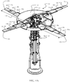
- FIG. 1A The embodiments described herein demonstrate a system as shown in FIG. 1A for a disc rotor 10 having multiple blades 12a, 12b, 12c and 12d, each rotor blade with three telescoping pieces; a root aero panel 14a, a mid aero panel 14b and an outer aero panel 14c.
- the blade panels are retracted into a central disc fairing 16 with a retraction mechanism, to be explained in greater detail subsequently, that retracts the rotor blade in two separate stages.
- the four rotor blades are mounted in opposing pairs at two different levels on the aircraft, a first pair with blades 12a and 12c above a second pair with blades 12b and 12d, vertically separated by a distance 13a (best seen in FIG.
- the two stage retraction system is shown schematically in FIG. 1B for one blade. A detailed mechanical embodiment is described subsequently.
- the first retraction stage operates with a complementary push-pull action using a geared electric actuator 20 driving a highly efficient ball screw 24 which is carried concentrically within a main blade spar 22.
- a ball nut 60 riding on ball screw 24 is connected to a piston head 62 integral with an inboard end of an intermediate spar 26 which telescopically receives the ball screw 24.
- the piston head 62 is carried in hydraulic cylinder 54 integral to the main blade spar 22. Pressurized hydraulic fluid is provided from an accumulator 74 into the hydraulic cylinder 54. Operation of the geared electric actuator 20 draws the ball nut 60 inboard within the main blade spar 22 while hydraulic pressure acting on piston head 62 complements that inboard motion.
- the tip aero panel 14c (shown in FIG. 1A ) is connected to an outboard fitting 80 of the intermediate spar 26 and the mid aero panel 14b (shown in FIG. 1A ) is carried by the intermediate spar. Retraction of the intermediate spar 26 into the main blade spar 22 draws the tip aero panel 14c telescopically into the mid aero panel 14b and the mid aero panel telescopically into the root aero panel 14a as will be described in greater detail subsequently.
- the second retraction stage employs a second geared electric actuator 30 which rotates an ACME nut 36 engaging an ACME thread 34 on the main blade spar 22. Rotation of the ACME nut withdraws the main blade spar 22 retracting the root aero panel 14c (with the telescopically nested tip a mid aero panels) into the disc fairing 16.
- the geared electric actuator 20 is mounted onto the main blade spar 22 to rotate ball screw 24 to retract the blade tip and mid aero panels.
- the ball screw 24 telescopes into titanium intermediate spar 26 during retraction.
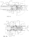
- the ball screw works in tandem with an accumulator powered hydraulic system that combines to push the tip and mid aero panels of the blade in, augmenting the ball screw, as will be described in greater detail subsequently with respect to FIG. 5A and 5B .
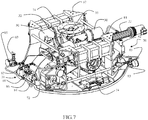
- the second retraction stage for each blade 12a, 12b, 12c and 12d is powered by the second geared electric actuator 30 mounted onto a rotor hub 32, the details of which will be described with respect to FIG. 4 .
- the second retraction stage operates with ACME screw thread 34 machined onto the main spar 22.
- ACME nut 36 (having an external bull gear 37 shown and described in greater detail with respect to FIG. 8 subsequently) engages the screw thread 34 for retraction and retention of main blade spar 22 and attached root aero panel 14a.
- grooves of a ball spline 38 extend longitudinally on the main blade spar 22 providing a second function of each main blade spar 22 for pitch control of the respective blade 12a, 12b, 12c, or 12d.
- a ball sleeve assembly 40 engages the ball spline 38 with inner ball sleeve 42 and outer ball sleeve 44 and serves to transfer blade loads from the main blade spar into pitch bearings 94 and 96 that fit around the outer diameter of sleeve assembly 40.
- a blade pitch arm 56 is connected to a pitch link 58 on the ball sleeve assembly 40 that is rotatable within roller pitch bearings 94 and 96 and centrifugal retention bearing 46 having rollers 47. This enables pitch control at any retraction position using the ball spline 38 engagement on main blade spar 22 with the ball sleeves 42, 44 in the ball sleeve assembly 40 rotating in pitch bearings 94 and 96 and retention bearing 46.
- the main blade spar 22 and associated ball sleeve assembly 40, pitch bearings 94 and 96 are mounted in a respective hub collar 48 in the hub 32 shown in FIG. 4 .
- Hub collars 48 are carried by rotor shaft 50 which is connected through a flange interface 52, at a bottom end, to power train 53 (shown in FIG. 1 ).
- Rotor shaft 50 also provides a disc fairing attachment bracket 55 at a top end.
- the main blade spar 22 is a multi function component.
- a chamber created by the internal diameter of the spar serves as a hydraulic cylinder 54 for the first stage retraction system.
- ball nut 60 rides on ball screw 24 and is attached to a piston head 62, which extends from the inboard end of intermediate spar 26, with a housing 63 using mating bolted flanges.
- a hydraulic cylinder head 64 inserted in the end of main blade spar 22 caps the hydraulic cylinder 54 and provides a hydraulic seal 65 through which intermediate spar 26 is received.
- Hydraulic fluid introduced through port 66 which for the embodiment shown is attached through a root forging 68 of the root aero panel 14a, flows into the hydraulic cylinder between the cylinder head 64 and piston head 62 through conduit 69.
- hydraulic fluid for each hydraulic cylinder is controlled through a valve manifold 70 connected to the port 66 through a flex line 72.
- An accumulator 74 connected to the manifold 70 stores hydraulic fluid at operating pressure.
- geared motor actuator 20 turns the ball screw 24 and the associated ball nut 60 attached to the hydraulic piston head 62 withdraws into the hydraulic cylinder.
- Pressurized hydraulic fluid is expelled from the accumulator during blade retraction urging the piston head from the outboard to inboard end of the hydraulic cylinder.
- Alignment of the ball screw at an outboard end is provided by self-aligning steady rest slider bearing 78 which rides on an inner circumference of intermediate spar 26 which is telescopically received over the ball screw and within the main blade spar.
- blade centrifugal force and power of the geared actuator 20 driving the ball screw 24 for extension of the ball nut 60 and attached piston head 62 are used to recharge the accumulator 74 with the piston head driving hydraulic fluid back through conduit 69, flex line 72 and manifold 70.
- the first retraction stage isolates the centrifugal load by, at first, retracting only the blade tip aero panel 14c, which is attached to an outboard fitting 80 on intermediate spar 26, telescopically into the blade mid aero panel 14b as shown in FIG. 9B . This is followed by retracting the collapsed blade tip aero panel 14c and mid aero panel 14b into root aero panel 14a as shown in FIG. 9C when the blade radius has been reduced and the tip loads are lower.
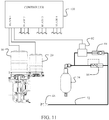
- manifold 70 incorporates a solenoid valve 82, a hydraulic check valve 84 for one way flow into the hydraulic cylinder, and a pressure relief valve 86 for cross flow in the hydraulic system to provide a means to recharge the accumulator.
- Each manifold includes a fill cock 83 and a pressure gage 85 for initial and maintenance filling of the accumulators.
- the solenoid valve 82 set for flow through the check valve 84, the check valve 84 acts as a brake and prevents the ball-screw from being back-driven by centrifugal force in the event of an electric actuator failure.
- the pressure relief valve 86 allows centrifugal force and actuator power to generate enough pressure to overcome the pressure setting and recharge the accumulator.
- the electric geared actuator 20 for each blade in the example embodiment incorporates an integral motor brake that serves as a backup for the hydraulic brake in the event of a hydraulic system failure.
- a geared actuator by Wittenstein Motion Control, part number TPM-004S-021M-5PB1-053B-W1 is employed for a 320 volt actuator with 21/1 gear ratio and including an encoder, a temperature sensor and a brake.
- the accumulators 74, hydraulic manifolds 70 and associated components are supported by a structural tray 87 mounted to the hub 32 within the disc fairing 16.
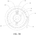
- each blade second geared actuator 30 provides rotational power through a shaft 88 to a pinion gear 90, as best seen in FIGs. 6A and 8 , which drives bull gear 37 on ACME nut 36 engaging ACME screw threads 34 (shown for only a portion of the spar length to allow clear display of the grooves of spline 38 engaged by ball sleeve 42) and the main blade spar 22 retracts through the ball sleeve assembly 40 and hub collar 48 in the opposite direction of the blade as shown in FIG. 10 .
- this configuration counter balances the blade during the second stage of retraction.
- the ACME-screw is replaced with a more efficient ball-screw that can function in combination with the ball-spline in a fashion similar to the first stage ball-screw.
- an integral motor brake in the second geared actuator 30 is applied to assist in holding the blade in the retracted position.
- spar 22 is a laminated structure of metal and carbon fiber composite.
- An outer shell of the spar is metal and provides both the grooves for the ball-spline 38 and the threads 34 for an interrupted ACME screw.
- the ACME screw 34 inherently has too much friction to be back-driven under load.
- a motor brake engages and the ACME screw serves as a friction break to hold the blade in its last position.
- an electronic controller 100 provides power to the geared actuators 20, 30 for all blades and can sense an actuator failure using sensor inputs from integral temperature sensors and encoders (or other sensors in alternative embodiments) indicating excessive temperatures or differences between commanded position and actual encoder position.. Controller 100 can command all remaining actuators to hold position with a failed unit at a calculated encoder position to prevent any rotor imbalance. Controller 100 additionally controls solenoid valve 82 for directional flow control of the hydraulic fluid through check valve 84.
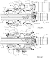
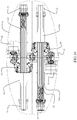
- the present embodiment employs an inner ball screw and blade retention bearing assembly 92 (best seen in FIGs. 6A and 6B ) carried in an inner end of the main blade spar 22 which also provides the inner seal for the hydraulic cylinder. Additionally, rotational support by bearing 46 for the ball sleeve assembly 40 is supplemented by inner and outer blade pitch roller bearings 94, 96.
- a retraction torque stop collar 98 (seen in FIGs. 6A and 6B ) prevents over rotation of the ball screw during retraction while an extension torque stop collar 99 (seen in FIGs. 5A and 5B ) prevents over rotation of the ball screw during extension of the blades.
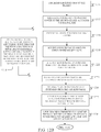
- operation of the disc rotor retraction system is conducted by the controller 100, which upon command for retraction of the blades, step 1200, by the vehicle pilot (or automated command system for unmanned vehicles), sets the solenoid valve 82 in manifold assembly 70 for flow through the check valve 84, step 1202, allowing hydraulic fluid to flow from the accumulator and provides power, step 1204, to the first geared actuator 20 for each blade.
- the controller 100 upon command for retraction of the blades, step 1200, by the vehicle pilot (or automated command system for unmanned vehicles), sets the solenoid valve 82 in manifold assembly 70 for flow through the check valve 84, step 1202, allowing hydraulic fluid to flow from the accumulator and provides power, step 1204, to the first geared actuator 20 for each blade.
- the tip aero panel 14c upon rotation of the ball screw 24 responsive to the geared actuator 20, and with the assistance of pressurized hydraulic fluid from accumulator 74 acting on the piston head 62, the tip aero panel 14c is telescopically withdrawn into the mid aero panel 14b, step 1206.
- the nested tip and mid panels are then drawn into the root aero panel 14a, step 1208 and upon reaching the retraction limit of the ball nut 60, the controller removes power from the geared actuator(s) 20 and applies a motor brake, step 1209.
- the controller then provides power, step 1210, to the second geared actuator 30 for each blade.
- Rotation of the second geared actuator 30, shaft 88, pinion gear 90 and bull gear 37 / ACME nut 36 results in withdrawing the main blade spar 22 by the ACME thread 34 through the ball sleeves 42, 44 of the ball sleeve assembly 40, step 1212, into the disc fairing 16.
- Pitch control of the blades may be accomplished at any time by input through the pitch arms 56 through pitch link 58 on each ball sleeve assembly 40 to rotate the ball sleeve assembly and, through engagement of the ball sleeves 42 and 44 by the ball spline 38, rotate the main blade spar and blade, step 1214.
- blade pitch must be held constant. Blade pitch must be held constant to prevent actuator 30 from being backdriven during the retraction process and to maintain blade clearance while entering the disc fairing 16.
- the motor brake is applied.
- controller 100 releases the motor brake and provides power to the second geared actuator 30 for each blade, step 1217.
- Counter rotation of the second geared actuator 30, shaft 88, pinion gear 90 and bull gear 37 /ACME nut 36 results in extension of the main blade spar 22 by the ACME thread 34 through the ball sleeves 42, 44 of the ball sleeve assembly 40, step 1218 to extend the root aero panel from the disc fairing 16.
- controller 100 positions solenoid valve 82 for flow of hydraulic fluid through the pressure relief valve 86, step 1220, releases the motor brake and provides power to the second gear actuator, step 1222, for each blade.
- the nested tip and mid panels are extended from the root aero panel 14a, step 1224, and the tip aero panel 14a is telescopically extended from the mid aero panel 14b, step 1226, with centrifugal force and power from the geared actuator pressurizing the hydraulic fluid for flow into the accumulator 74, step 1227.
- the blades are fully extended and the controller removes power from the geared actuator(s) 20, step 1228 and applies a motor brake.
Landscapes
- Engineering & Computer Science (AREA)
- Aviation & Aerospace Engineering (AREA)
- Mechanical Engineering (AREA)
- Physics & Mathematics (AREA)
- Fluid Mechanics (AREA)
- Braking Arrangements (AREA)
- Wind Motors (AREA)
- Transmission Devices (AREA)
- Actuator (AREA)
- Structures Of Non-Positive Displacement Pumps (AREA)
Claims (12)
- Système de rétraction de pale de rotor discoïde comprenant :un longeron de pale principal (22) incorporant un vérin hydraulique (54) et comportant un filetage (34) ;une vis à bille (24) supportée concentriquement à l'intérieur du longeron de pale principal (22) et supportant fonctionnellement un écrou à bille (60) comportant une extrémité extérieure reliée à un longeron intermédiaire (26) et à un piston hydraulique (62) logé dans le vérin hydraulique (54) de manière à effectuer un mouvement alternatif ;un premier actionneur à engrenages (20) s'engageant fonctionnellement avec la vis à bille (24) ;un deuxième actionneur à engrenages (30) s'engageant fonctionnellement avec le filetage du longeron de pale principal (34) ;un accumulateur de fluide hydraulique (74) relié à une extrémité extérieure du vérin hydraulique (54) ; et,un dispositif de commande destiné à actionner les premier et deuxième actionneurs à engrenages (20, 30).
- Système de rétraction de pale de rotor discoïde selon la revendication 1, comprenant en outre un ensemble de commande de pas s'engageant concentriquement avec le longeron de pale principal (22).
- Système de rétraction de pale de rotor discoïde selon la revendication 2, dans lequel l'ensemble de commande de pas comprend un manchon à bille s'engageant avec des rainures d'une cannelure à bille (38) du longeron de pale principal (22) .
- Système de rétraction de pale de rotor discoïde selon la revendication 2, dans lequel l'ensemble de commande de pas est monté de manière à tourner dans un collier (48) supporté par un moyeu de rotor (32).
- Système de rétraction de pale de rotor discoïde selon la revendication 1, dans lequel le longeron intermédiaire (26) supporte au moins un panneau aérodynamique extérieur (14c).
- Système de rétraction de pale de rotor discoïde selon la revendication 5, dans lequel le longeron intermédiaire (26) est relié, au niveau d'une extrémité extérieure, à un panneau aérodynamique de pointe (14c) pouvant être reçu dans un panneau aérodynamique intermédiaire (14b) lors de la rétraction.
- Système de rétraction de pale de rotor discoïde selon la revendication 6, dans lequel ledit panneau aérodynamique intermédiaire (14b) est rétractable dans un panneau aérodynamique de base (14a) supporté par le longeron de pale principal (22), ledit panneau aérodynamique de base étant rétractable dans un carénage discoïde (16).
- Système de rétraction de pale de rotor discoïde selon la revendication 1, comprenant en outre un collecteur de fluide (70) incorporant
un clapet anti-retour (84) situé entre l'accumulateur (74) et le vérin hydraulique (54) ;
une soupape de surpression (86) située entre l'accumulateur (74) et le vérin hydraulique (54) ; et
une électrovanne (82) reliant sélectivement la soupape de surpression (86) au vérin hydraulique (54), ladite électrovanne (82) réagissant au dispositif de commande. - Procédé de fonctionnement d'une pale de rotor discoïdal comprenant les étapes suivantes :commander la rétraction d'une pluralité de pales ;pour chaque pale,régler une électrovanne (82) pour que le fluide hydraulique s'écoule à travers un clapet anti-retour (84) depuis un accumulateur (74) ;alimenter en énergie un premier actionneur à engrenages (20) ;faire tourner une vis à bille (24) en réponse à l'actionneur à engrenages (20) et à l'aide du fluide hydraulique sous pression provenant l'accumulateur (74) agissant sur une tête de piston (62), ce qui replie de manière télescopique un panneau aérodynamique de pointe (14c), relié à un écrou à bille (60), dans un panneau aérodynamique intermédiaire (14b) ;replier les panneaux aérodynamiques de pointe et intermédiaire emboîtés (14a, 14c) dans un panneau aérodynamique de base (14b) ;lorsqu'une limite de rétraction de l'écrou à bille (60) sur la vis à bille (24) est atteinte, ne plus alimenter l'actionneur à engrenages (20) ;alimenter en énergie un deuxième actionneur à engrenages (30) pour chaque pale ; et,faire tourner un écrou (60) avec le deuxième actionneur à engrenages (30), ledit écrou (60) agissant sur un filetage (34) d'un longeron de pale principal (22) supportant le panneau aérodynamique de base (14a) de manière à replier le longeron de pale principal (22) dans un carénage discoïde (16).
- Procédé selon la revendication 9, dans lequel le longeron de pale principal (22) comprend une cannelure rainurée (38) et l'étape de rotation d'un écrou (60) comprend en outre les étapes suivantes :replier le longeron de pale principal (22) à travers un ensemble de manchon à bille ;commander le pas sur chaque pale par une entrée par le biais des bras de pas (56) reliés à chaque ensemble de manchon à bille (42, 44) pour faire tourner l'ensemble de manchon à bille et, par engagement de l'ensemble de manchon à bille par la cannelure à bille (38), faire tourner le longeron de pale principal (22) et la pale.
- Procédé selon la revendication 9, comprenant en outre les étapes suivantes :commander l'extension des pales ;pour chaque pale,alimenter en énergie le deuxième actionneur à engrenages (30) pour faire tourner l'écrou (60) en sens inverse ;effectuer l'extension du longeron de pale principal (22) au moyen du filetage pour étendre le panneau aérodynamique de base (14a) depuis le carénage discoïdal (16) ;lors de l'extension complète du panneau aérodynamique de base (14a), positionner l'électrovanne (82) de manière à ce que le fluide hydraulique s'écoule à travers le régulateur ;alimenter en énergie le premier actionneur à engrenages (20) pour faire tourner la vis à bille (24) dans le sens inverse ;effectuer l'extension des panneaux de pointe et intermédiaire emboîtés (14b, 14c) depuis le panneau aérodynamique de base (14c) ;par la force centrifuge et la puissance provenant de l'actionneur à engrenages (20), mettre le fluide hydraulique sous pression pour qu'il s'écoule dans l'accumulateur (74) ;une fois la limite d'extension de l'écrou à bille (60) atteinte, ne plus alimenter en énergie le premier actionneur à engrenages (20).
- Procédé selon la revendication 9, comprenant en outre l'application d'un frein moteur lorsque l'actionneur à engrenages (20) n'est plus alimenté en énergie.
Applications Claiming Priority (1)
| Application Number | Priority Date | Filing Date | Title |
|---|---|---|---|
| US13/037,205 US8784057B2 (en) | 2011-02-28 | 2011-02-28 | Disc rotor retraction system |
Publications (3)
| Publication Number | Publication Date |
|---|---|
| EP2492192A2 EP2492192A2 (fr) | 2012-08-29 |
| EP2492192A3 EP2492192A3 (fr) | 2017-08-30 |
| EP2492192B1 true EP2492192B1 (fr) | 2018-11-14 |
Family
ID=45811289
Family Applications (1)
| Application Number | Title | Priority Date | Filing Date |
|---|---|---|---|
| EP12157385.1A Active EP2492192B1 (fr) | 2011-02-28 | 2012-02-28 | Système de rétraction de rotor de disque |
Country Status (5)
| Country | Link |
|---|---|
| US (1) | US8784057B2 (fr) |
| EP (1) | EP2492192B1 (fr) |
| JP (1) | JP5872284B2 (fr) |
| CN (1) | CN102649476B (fr) |
| CA (1) | CA2760021C (fr) |
Families Citing this family (44)
| Publication number | Priority date | Publication date | Assignee | Title |
|---|---|---|---|---|
| US9079659B2 (en) * | 2010-09-09 | 2015-07-14 | General Aeronautics Corporation, Inc. | Rotor hub and blade root fairing apparatus and method |
| EP2727832B1 (fr) * | 2012-10-31 | 2016-06-22 | AIRBUS HELICOPTERS DEUTSCHLAND GmbH | Tête de rotor d'appareil volante à voilure tournante et son procédé de fabrication et d'assemblage |
| RU2549429C1 (ru) * | 2014-02-03 | 2015-04-27 | Виталий Владимирович Павлов | Способ преобразования самолета вертикального взлета и посадки |
| US9522725B2 (en) * | 2014-02-13 | 2016-12-20 | Northrup Grumman Systems Corporation | Stowable and deployable unmanned aerial vehicle |
| EP3119674B1 (fr) * | 2014-03-18 | 2020-11-11 | Joby Aero, Inc. | Système de propulsion résistant aux chocs |
| CN103979107B (zh) * | 2014-05-21 | 2016-01-20 | 北京理工大学 | 一种折叠式旋翼型无人机 |
| US9540103B2 (en) * | 2014-06-24 | 2017-01-10 | Kitty Hawk Corporation | Passive deployment mechanism for lift fan |
| CN104507800B (zh) | 2014-06-26 | 2016-08-31 | 深圳市大疆创新科技有限公司 | 变形飞行器 |
| FR3026387B1 (fr) * | 2014-09-26 | 2016-10-21 | Airbus Helicopters | Carenage de rotor, rotor et aeronef |
| FR3028838B1 (fr) | 2014-11-20 | 2016-11-18 | Airbus Helicopters | Aeronef a voilure tournante muni d'un rotor arriere non carene comprenant au moins cinq pales |
| CN105605008B (zh) * | 2014-11-20 | 2017-11-03 | 中国直升机设计研究所 | 一种用于转输液体的分流器 |
| CN104787328B (zh) * | 2015-04-01 | 2016-08-24 | 北京航空航天大学 | 一种适用于复合式飞机的旋翼折展机构 |
| CN104773291A (zh) * | 2015-04-08 | 2015-07-15 | 南昌航空大学 | 一种盘型旋翼无人直升机 |
| CN104816825B (zh) * | 2015-04-13 | 2016-08-31 | 北京航空航天大学 | 一种伸缩折展旋翼 |
| CN104943853B (zh) * | 2015-04-27 | 2017-04-05 | 西北工业大学 | 一种能够变径的螺旋桨 |
| US10302064B2 (en) | 2015-07-30 | 2019-05-28 | The Boeing Company | Methods and systems for rotary wing active flow control |
| RU2609847C1 (ru) * | 2015-07-31 | 2017-02-06 | Виталий Владимирович Павлов | Способ преобразования дискового крыла в несущий винт |
| CN105673573A (zh) * | 2015-12-29 | 2016-06-15 | 刘夏菲 | 一种吊风扇平衡装置 |
| CN105947182B (zh) * | 2016-05-25 | 2019-02-19 | 李帜 | 一种可折叠螺旋桨和飞行器 |
| US10814959B2 (en) * | 2016-09-30 | 2020-10-27 | General Electric Company | Translating fan blades for an aircraft tail mounted fan assembly |
| US10752371B2 (en) * | 2016-09-30 | 2020-08-25 | General Electric Company | Translating nacelle wall for an aircraft tail mounted fan section |
| CN106427438B (zh) * | 2016-10-18 | 2018-10-16 | 南京航空航天大学 | 一种旋翼可收放的陆空两用飞车及其控制方法 |
| US10626846B2 (en) * | 2016-11-17 | 2020-04-21 | General Electric Company | System for wind turbine blade actuation |
| CN106640479A (zh) * | 2016-12-31 | 2017-05-10 | 毛永波 | 一种轴向流力伸缩叶流轮 |
| CN111810443A (zh) * | 2016-12-31 | 2020-10-23 | 毛永波 | 套管活塞缸伸缩隐形扇叶风轮与风扇 |
| CN106915460B (zh) * | 2017-02-22 | 2019-04-26 | 北京航空航天大学 | 一种折展旋翼机构 |
| CN106741857A (zh) * | 2017-03-02 | 2017-05-31 | 南京那尔朴电子有限公司 | 一种可以推力调节的螺旋桨 |
| CN108657427A (zh) * | 2017-03-28 | 2018-10-16 | 天津京东智联科技发展有限公司 | 一种桨叶 |
| US11192644B2 (en) * | 2017-06-16 | 2021-12-07 | Airbus Helicopters | Aircraft rotor blade sleeve having a protuberance in its rear zone, and a rotor provided with such a sleeve |
| CN107763367B (zh) * | 2017-11-16 | 2023-08-01 | 北华大学 | 螺旋驱动离心式机械自适应调速装置 |
| CN110081001B (zh) * | 2018-01-26 | 2020-08-07 | 兰永庆 | 一种机械伸缩隐形扇 |
| CN211010415U (zh) * | 2019-03-08 | 2020-07-14 | 杜书勇 | 管道内检测车 |
| CN108621725B (zh) * | 2018-05-09 | 2021-02-05 | 东北石油大学 | 一种折叠式螺旋桨 |
| KR102034010B1 (ko) * | 2018-08-20 | 2019-10-18 | 금오공과대학교 산학협력단 | 회전익 자동 강성 조절 장치 |
| CN112607003B (zh) * | 2020-11-25 | 2023-06-20 | 常州市长昊机械有限公司 | 一种易收纳式航空叶片 |
| CN112455650A (zh) * | 2020-11-26 | 2021-03-09 | 广东国士健科技发展有限公司 | 一种双翼飞行装置 |
| TR202022410A1 (tr) * | 2020-12-30 | 2022-07-21 | Tusas Tuerk Havacilik Ve Uzay Sanayii Anonim Sirketi | Döner kanatlı hava aracı. |
| CN113232853B (zh) * | 2021-04-02 | 2022-11-04 | 陈�峰 | 一种短距起降飞机 |
| CN112918671B (zh) * | 2021-04-07 | 2022-04-26 | 北京航空航天大学 | 一种用于纵列双旋翼直升机的旋翼自动折叠系统 |
| KR20220168902A (ko) * | 2021-06-17 | 2022-12-26 | 현대자동차주식회사 | 에어모빌리티의 프로펠러 제어 시스템 |
| CN114426098A (zh) * | 2022-02-28 | 2022-05-03 | 上海埃依斯航天科技有限公司 | 一种新型盘翼 |
| CN115303304B (zh) * | 2022-07-26 | 2023-06-23 | 华设设计集团股份有限公司 | 一种高速列车升力翼装置 |
| CN117657497B (zh) * | 2023-12-14 | 2026-03-03 | 中国融通集团第六十研究所 | 一种可变构型的螺旋桨系统及其调节方法 |
| CN117554023B (zh) * | 2024-01-11 | 2024-06-25 | 中国航空工业集团公司哈尔滨空气动力研究所 | 一种用于风洞内螺旋桨试验所需的螺旋桨自动变桨距装置 |
Family Cites Families (22)
| Publication number | Priority date | Publication date | Assignee | Title |
|---|---|---|---|---|
| US1922866A (en) * | 1932-04-22 | 1933-08-15 | Rosenberg Sandor | Rotary airfoil |
| US2713393A (en) * | 1952-06-10 | 1955-07-19 | Isacco Vittorio | Telescopic blade for rotating wing aircraft |
| US3065938A (en) * | 1960-05-25 | 1962-11-27 | Eugene M Calkins | Telescoping sectional airplane wing |
| US3249160A (en) * | 1964-06-10 | 1966-05-03 | Messerschmitt Ag | Rotor blade construction for aircraft |
| US3501248A (en) * | 1967-05-17 | 1970-03-17 | Friedrich W Brocker | Variable diameter propellers |
| CA1017729A (en) | 1968-09-12 | 1977-09-20 | Evan A. Fradenburgh | Mechanism for synchronously varying diameter of a plurality of rotors and for limiting the diameters thereof |
| US3768923A (en) * | 1969-09-18 | 1973-10-30 | United Aircraft Corp | Variable length blade |
| US3713751A (en) * | 1970-10-29 | 1973-01-30 | United Aircraft Corp | Aerodynamic blade with high stiffness-to-weight ratio |
| US3814351A (en) * | 1972-12-06 | 1974-06-04 | United Aircraft Corp | Coaxial rotor yaw control |
| FR2683503B1 (fr) * | 1991-11-07 | 1994-02-25 | Aerospatiale Ste Nationale Indle | Ensemble de freinage de rotor de giravion. |
| US5735670A (en) | 1995-12-11 | 1998-04-07 | Sikorsky Aircraft Corporation | Rotor system having alternating length rotor blades and positioning means therefor for reducing blade-vortex interaction (BVI) noise |
| JP2001132615A (ja) * | 1999-11-11 | 2001-05-18 | Hitachi Zosen Corp | 発電用プロペラ形風車 |
| FR2806452B1 (fr) * | 2000-03-20 | 2002-05-03 | Hutchinson | Amortisseur de vibrations notamment pour rotor d'helicoptere |
| US6972498B2 (en) * | 2002-05-28 | 2005-12-06 | General Electric Company | Variable diameter wind turbine rotor blades |
| US6902370B2 (en) * | 2002-06-04 | 2005-06-07 | Energy Unlimited, Inc. | Telescoping wind turbine blade |
| US7475847B2 (en) * | 2002-09-09 | 2009-01-13 | Gerbino Allen J | Retractable lifting blades for aircraft |
| US7581926B1 (en) * | 2004-03-22 | 2009-09-01 | Clipper Windpower Technology, Inc. | Servo-controlled extender mechanism for extendable rotor blades for power generating wind and ocean current turbines |
| US20080014087A1 (en) * | 2006-07-17 | 2008-01-17 | Enjoy Toy & Hobby Corp. | Tail rotor for remotely controlled toy helicopter |
| EP2162353B1 (fr) * | 2007-05-24 | 2010-10-06 | Georgian Technical University (GTU) | Rotor à diamètre variable avec mécanisme de compensation de forces centrifuges |
| US8360721B2 (en) | 2008-01-08 | 2013-01-29 | The Boeing Company | Low maintenance stiff in plane gimbaled rotor head |
| US9068818B2 (en) * | 2010-02-24 | 2015-06-30 | Sikorsky Aircraft Corporation | Drive mechanisms for variable diameter rotor systems |
| FR2960827A1 (fr) * | 2010-06-07 | 2011-12-09 | Raphael Christian Anne Marie Luminais | Dispositif stabilisateur amphibie, aerien, urbain |
-
2011
- 2011-02-28 US US13/037,205 patent/US8784057B2/en active Active
- 2011-12-01 CA CA2760021A patent/CA2760021C/fr active Active
- 2011-12-28 JP JP2011288557A patent/JP5872284B2/ja active Active
-
2012
- 2012-02-14 CN CN201210032548.5A patent/CN102649476B/zh active Active
- 2012-02-28 EP EP12157385.1A patent/EP2492192B1/fr active Active
Non-Patent Citations (1)
| Title |
|---|
| None * |
Also Published As
| Publication number | Publication date |
|---|---|
| CN102649476A (zh) | 2012-08-29 |
| CA2760021C (fr) | 2014-10-07 |
| EP2492192A2 (fr) | 2012-08-29 |
| CA2760021A1 (fr) | 2012-08-28 |
| US8784057B2 (en) | 2014-07-22 |
| JP5872284B2 (ja) | 2016-03-01 |
| US20120219417A1 (en) | 2012-08-30 |
| CN102649476B (zh) | 2016-05-25 |
| EP2492192A3 (fr) | 2017-08-30 |
| JP2012180083A (ja) | 2012-09-20 |
Similar Documents
| Publication | Publication Date | Title |
|---|---|---|
| EP2492192B1 (fr) | Système de rétraction de rotor de disque | |
| EP3095693B1 (fr) | Système de direction d'aéronef | |
| EP2837558B1 (fr) | Procédé et appareil de connexion d'un système d'entraînement fixé à un système d'entraînement rotatif pour un aéronef à rotors basculants | |
| EP2690007B1 (fr) | Procédé de production d'énergie hydraulique dans un aéronef, utilisation d'une unité de commande d'énergie hybride et d'un système d'entraînement | |
| EP2982603A1 (fr) | Système d'entraînement de train d'atterrissage | |
| US8702035B2 (en) | Actuation apparatus for use on an aircraft | |
| EP2440453B1 (fr) | Dispositif pour l'actionnement d'une surface de commande d'un aéronef | |
| EP3781476B1 (fr) | Système pour une aile d'aéronef | |
| CN105173066A (zh) | 一种无人机电驱动前轮转弯装置 | |
| EP3116778B1 (fr) | Ensemble roue et engrenage | |
| EP2234878B1 (fr) | Ensemble ecrou de blocage pour arbre coaxial | |
| EP3848279B1 (fr) | Systèmes de collecte d'énergie de roue rotationnelle de rétraction de train d'atterrissage | |
| US10023304B2 (en) | Tail rotor actuation system | |
| EP4549315B1 (fr) | Ema rotatif insensible aux défaillances | |
| CN1980010A (zh) | 容错机电致动器 | |
| US12600469B2 (en) | Propulsor external hydraulic control system | |
| EP4491510A1 (fr) | Système d'entraînement à volet unique pour architectures de volet décentralisées | |
| US20250313333A1 (en) | Axially Aligned Triplex Linear Hydraulic Actuators | |
| EP3038911B1 (fr) | Aéronef à élément d'entraînement couplé à l'extérieur du carter de boîte d'engrenages | |
| WO2025177112A1 (fr) | Unité électromécanique pour hélice à pas variable | |
| EP3483061A1 (fr) | Commande de roulage taxi améliorée pour des rotors rigides |
Legal Events
| Date | Code | Title | Description |
|---|---|---|---|
| PUAI | Public reference made under article 153(3) epc to a published international application that has entered the european phase |
Free format text: ORIGINAL CODE: 0009012 |
|
| 17P | Request for examination filed |
Effective date: 20120228 |
|
| AK | Designated contracting states |
Kind code of ref document: A2 Designated state(s): AL AT BE BG CH CY CZ DE DK EE ES FI FR GB GR HR HU IE IS IT LI LT LU LV MC MK MT NL NO PL PT RO RS SE SI SK SM TR |
|
| AX | Request for extension of the european patent |
Extension state: BA ME |
|
| PUAL | Search report despatched |
Free format text: ORIGINAL CODE: 0009013 |
|
| AK | Designated contracting states |
Kind code of ref document: A3 Designated state(s): AL AT BE BG CH CY CZ DE DK EE ES FI FR GB GR HR HU IE IS IT LI LT LU LV MC MK MT NL NO PL PT RO RS SE SI SK SM TR |
|
| AX | Request for extension of the european patent |
Extension state: BA ME |
|
| RIC1 | Information provided on ipc code assigned before grant |
Ipc: B64C 27/46 20060101ALI20170721BHEP Ipc: B64C 27/30 20060101ALI20170721BHEP Ipc: B64C 27/32 20060101AFI20170721BHEP Ipc: B64C 11/00 20060101ALI20170721BHEP |
|
| GRAP | Despatch of communication of intention to grant a patent |
Free format text: ORIGINAL CODE: EPIDOSNIGR1 |
|
| STAA | Information on the status of an ep patent application or granted ep patent |
Free format text: STATUS: GRANT OF PATENT IS INTENDED |
|
| INTG | Intention to grant announced |
Effective date: 20180619 |
|
| GRAS | Grant fee paid |
Free format text: ORIGINAL CODE: EPIDOSNIGR3 |
|
| GRAA | (expected) grant |
Free format text: ORIGINAL CODE: 0009210 |
|
| STAA | Information on the status of an ep patent application or granted ep patent |
Free format text: STATUS: THE PATENT HAS BEEN GRANTED |
|
| AK | Designated contracting states |
Kind code of ref document: B1 Designated state(s): AL AT BE BG CH CY CZ DE DK EE ES FI FR GB GR HR HU IE IS IT LI LT LU LV MC MK MT NL NO PL PT RO RS SE SI SK SM TR |
|
| REG | Reference to a national code |
Ref country code: CH Ref legal event code: EP Ref country code: AT Ref legal event code: REF Ref document number: 1064487 Country of ref document: AT Kind code of ref document: T Effective date: 20181115 |
|
| REG | Reference to a national code |
Ref country code: DE Ref legal event code: R096 Ref document number: 602012053380 Country of ref document: DE |
|
| REG | Reference to a national code |
Ref country code: IE Ref legal event code: FG4D |
|
| REG | Reference to a national code |
Ref country code: NL Ref legal event code: MP Effective date: 20181114 |
|
| REG | Reference to a national code |
Ref country code: LT Ref legal event code: MG4D |
|
| REG | Reference to a national code |
Ref country code: AT Ref legal event code: MK05 Ref document number: 1064487 Country of ref document: AT Kind code of ref document: T Effective date: 20181114 |
|
| PG25 | Lapsed in a contracting state [announced via postgrant information from national office to epo] |
Ref country code: HR Free format text: LAPSE BECAUSE OF FAILURE TO SUBMIT A TRANSLATION OF THE DESCRIPTION OR TO PAY THE FEE WITHIN THE PRESCRIBED TIME-LIMIT Effective date: 20181114 Ref country code: LT Free format text: LAPSE BECAUSE OF FAILURE TO SUBMIT A TRANSLATION OF THE DESCRIPTION OR TO PAY THE FEE WITHIN THE PRESCRIBED TIME-LIMIT Effective date: 20181114 Ref country code: AT Free format text: LAPSE BECAUSE OF FAILURE TO SUBMIT A TRANSLATION OF THE DESCRIPTION OR TO PAY THE FEE WITHIN THE PRESCRIBED TIME-LIMIT Effective date: 20181114 Ref country code: NO Free format text: LAPSE BECAUSE OF FAILURE TO SUBMIT A TRANSLATION OF THE DESCRIPTION OR TO PAY THE FEE WITHIN THE PRESCRIBED TIME-LIMIT Effective date: 20190214 Ref country code: LV Free format text: LAPSE BECAUSE OF FAILURE TO SUBMIT A TRANSLATION OF THE DESCRIPTION OR TO PAY THE FEE WITHIN THE PRESCRIBED TIME-LIMIT Effective date: 20181114 Ref country code: FI Free format text: LAPSE BECAUSE OF FAILURE TO SUBMIT A TRANSLATION OF THE DESCRIPTION OR TO PAY THE FEE WITHIN THE PRESCRIBED TIME-LIMIT Effective date: 20181114 Ref country code: IS Free format text: LAPSE BECAUSE OF FAILURE TO SUBMIT A TRANSLATION OF THE DESCRIPTION OR TO PAY THE FEE WITHIN THE PRESCRIBED TIME-LIMIT Effective date: 20190314 Ref country code: ES Free format text: LAPSE BECAUSE OF FAILURE TO SUBMIT A TRANSLATION OF THE DESCRIPTION OR TO PAY THE FEE WITHIN THE PRESCRIBED TIME-LIMIT Effective date: 20181114 Ref country code: BG Free format text: LAPSE BECAUSE OF FAILURE TO SUBMIT A TRANSLATION OF THE DESCRIPTION OR TO PAY THE FEE WITHIN THE PRESCRIBED TIME-LIMIT Effective date: 20190214 |
|
| PG25 | Lapsed in a contracting state [announced via postgrant information from national office to epo] |
Ref country code: GR Free format text: LAPSE BECAUSE OF FAILURE TO SUBMIT A TRANSLATION OF THE DESCRIPTION OR TO PAY THE FEE WITHIN THE PRESCRIBED TIME-LIMIT Effective date: 20190215 Ref country code: PT Free format text: LAPSE BECAUSE OF FAILURE TO SUBMIT A TRANSLATION OF THE DESCRIPTION OR TO PAY THE FEE WITHIN THE PRESCRIBED TIME-LIMIT Effective date: 20190314 Ref country code: NL Free format text: LAPSE BECAUSE OF FAILURE TO SUBMIT A TRANSLATION OF THE DESCRIPTION OR TO PAY THE FEE WITHIN THE PRESCRIBED TIME-LIMIT Effective date: 20181114 Ref country code: AL Free format text: LAPSE BECAUSE OF FAILURE TO SUBMIT A TRANSLATION OF THE DESCRIPTION OR TO PAY THE FEE WITHIN THE PRESCRIBED TIME-LIMIT Effective date: 20181114 Ref country code: SE Free format text: LAPSE BECAUSE OF FAILURE TO SUBMIT A TRANSLATION OF THE DESCRIPTION OR TO PAY THE FEE WITHIN THE PRESCRIBED TIME-LIMIT Effective date: 20181114 Ref country code: RS Free format text: LAPSE BECAUSE OF FAILURE TO SUBMIT A TRANSLATION OF THE DESCRIPTION OR TO PAY THE FEE WITHIN THE PRESCRIBED TIME-LIMIT Effective date: 20181114 |
|
| PG25 | Lapsed in a contracting state [announced via postgrant information from national office to epo] |
Ref country code: PL Free format text: LAPSE BECAUSE OF FAILURE TO SUBMIT A TRANSLATION OF THE DESCRIPTION OR TO PAY THE FEE WITHIN THE PRESCRIBED TIME-LIMIT Effective date: 20181114 Ref country code: CZ Free format text: LAPSE BECAUSE OF FAILURE TO SUBMIT A TRANSLATION OF THE DESCRIPTION OR TO PAY THE FEE WITHIN THE PRESCRIBED TIME-LIMIT Effective date: 20181114 Ref country code: IT Free format text: LAPSE BECAUSE OF FAILURE TO SUBMIT A TRANSLATION OF THE DESCRIPTION OR TO PAY THE FEE WITHIN THE PRESCRIBED TIME-LIMIT Effective date: 20181114 Ref country code: DK Free format text: LAPSE BECAUSE OF FAILURE TO SUBMIT A TRANSLATION OF THE DESCRIPTION OR TO PAY THE FEE WITHIN THE PRESCRIBED TIME-LIMIT Effective date: 20181114 |
|
| REG | Reference to a national code |
Ref country code: DE Ref legal event code: R097 Ref document number: 602012053380 Country of ref document: DE |
|
| PG25 | Lapsed in a contracting state [announced via postgrant information from national office to epo] |
Ref country code: SM Free format text: LAPSE BECAUSE OF FAILURE TO SUBMIT A TRANSLATION OF THE DESCRIPTION OR TO PAY THE FEE WITHIN THE PRESCRIBED TIME-LIMIT Effective date: 20181114 Ref country code: EE Free format text: LAPSE BECAUSE OF FAILURE TO SUBMIT A TRANSLATION OF THE DESCRIPTION OR TO PAY THE FEE WITHIN THE PRESCRIBED TIME-LIMIT Effective date: 20181114 Ref country code: SK Free format text: LAPSE BECAUSE OF FAILURE TO SUBMIT A TRANSLATION OF THE DESCRIPTION OR TO PAY THE FEE WITHIN THE PRESCRIBED TIME-LIMIT Effective date: 20181114 Ref country code: RO Free format text: LAPSE BECAUSE OF FAILURE TO SUBMIT A TRANSLATION OF THE DESCRIPTION OR TO PAY THE FEE WITHIN THE PRESCRIBED TIME-LIMIT Effective date: 20181114 |
|
| PLBE | No opposition filed within time limit |
Free format text: ORIGINAL CODE: 0009261 |
|
| STAA | Information on the status of an ep patent application or granted ep patent |
Free format text: STATUS: NO OPPOSITION FILED WITHIN TIME LIMIT |
|
| REG | Reference to a national code |
Ref country code: CH Ref legal event code: PL |
|
| 26N | No opposition filed |
Effective date: 20190815 |
|
| PG25 | Lapsed in a contracting state [announced via postgrant information from national office to epo] |
Ref country code: LU Free format text: LAPSE BECAUSE OF NON-PAYMENT OF DUE FEES Effective date: 20190228 Ref country code: MC Free format text: LAPSE BECAUSE OF FAILURE TO SUBMIT A TRANSLATION OF THE DESCRIPTION OR TO PAY THE FEE WITHIN THE PRESCRIBED TIME-LIMIT Effective date: 20181114 Ref country code: SI Free format text: LAPSE BECAUSE OF FAILURE TO SUBMIT A TRANSLATION OF THE DESCRIPTION OR TO PAY THE FEE WITHIN THE PRESCRIBED TIME-LIMIT Effective date: 20181114 |
|
| REG | Reference to a national code |
Ref country code: BE Ref legal event code: MM Effective date: 20190228 |
|
| REG | Reference to a national code |
Ref country code: IE Ref legal event code: MM4A |
|
| PG25 | Lapsed in a contracting state [announced via postgrant information from national office to epo] |
Ref country code: LI Free format text: LAPSE BECAUSE OF NON-PAYMENT OF DUE FEES Effective date: 20190228 Ref country code: CH Free format text: LAPSE BECAUSE OF NON-PAYMENT OF DUE FEES Effective date: 20190228 |
|
| PG25 | Lapsed in a contracting state [announced via postgrant information from national office to epo] |
Ref country code: IE Free format text: LAPSE BECAUSE OF NON-PAYMENT OF DUE FEES Effective date: 20190228 |
|
| PG25 | Lapsed in a contracting state [announced via postgrant information from national office to epo] |
Ref country code: BE Free format text: LAPSE BECAUSE OF NON-PAYMENT OF DUE FEES Effective date: 20190228 |
|
| PG25 | Lapsed in a contracting state [announced via postgrant information from national office to epo] |
Ref country code: TR Free format text: LAPSE BECAUSE OF FAILURE TO SUBMIT A TRANSLATION OF THE DESCRIPTION OR TO PAY THE FEE WITHIN THE PRESCRIBED TIME-LIMIT Effective date: 20181114 |
|
| PG25 | Lapsed in a contracting state [announced via postgrant information from national office to epo] |
Ref country code: MT Free format text: LAPSE BECAUSE OF NON-PAYMENT OF DUE FEES Effective date: 20190228 |
|
| PG25 | Lapsed in a contracting state [announced via postgrant information from national office to epo] |
Ref country code: CY Free format text: LAPSE BECAUSE OF FAILURE TO SUBMIT A TRANSLATION OF THE DESCRIPTION OR TO PAY THE FEE WITHIN THE PRESCRIBED TIME-LIMIT Effective date: 20181114 |
|
| PG25 | Lapsed in a contracting state [announced via postgrant information from national office to epo] |
Ref country code: HU Free format text: LAPSE BECAUSE OF FAILURE TO SUBMIT A TRANSLATION OF THE DESCRIPTION OR TO PAY THE FEE WITHIN THE PRESCRIBED TIME-LIMIT; INVALID AB INITIO Effective date: 20120228 |
|
| PG25 | Lapsed in a contracting state [announced via postgrant information from national office to epo] |
Ref country code: MK Free format text: LAPSE BECAUSE OF FAILURE TO SUBMIT A TRANSLATION OF THE DESCRIPTION OR TO PAY THE FEE WITHIN THE PRESCRIBED TIME-LIMIT Effective date: 20181114 |
|
| P01 | Opt-out of the competence of the unified patent court (upc) registered |
Effective date: 20230516 |
|
| PGFP | Annual fee paid to national office [announced via postgrant information from national office to epo] |
Ref country code: GB Payment date: 20260227 Year of fee payment: 15 |
|
| PGFP | Annual fee paid to national office [announced via postgrant information from national office to epo] |
Ref country code: DE Payment date: 20260227 Year of fee payment: 15 |
|
| PGFP | Annual fee paid to national office [announced via postgrant information from national office to epo] |
Ref country code: FR Payment date: 20260225 Year of fee payment: 15 |