EP2492421B1 - Key and lock cylinder combination - Google Patents
Key and lock cylinder combination Download PDFInfo
- Publication number
- EP2492421B1 EP2492421B1 EP11075140.1A EP11075140A EP2492421B1 EP 2492421 B1 EP2492421 B1 EP 2492421B1 EP 11075140 A EP11075140 A EP 11075140A EP 2492421 B1 EP2492421 B1 EP 2492421B1
- Authority
- EP
- European Patent Office
- Prior art keywords
- key
- locking pin
- magnet
- keyway
- cylinder
- Prior art date
- Legal status (The legal status is an assumption and is not a legal conclusion. Google has not performed a legal analysis and makes no representation as to the accuracy of the status listed.)
- Active
Links
Images
Classifications
-
- E—FIXED CONSTRUCTIONS
- E05—LOCKS; KEYS; WINDOW OR DOOR FITTINGS; SAFES
- E05B—LOCKS; ACCESSORIES THEREFOR; HANDCUFFS
- E05B17/00—Accessories in connection with locks
- E05B17/14—Closures or guards for keyholes
- E05B17/16—Closures or guards for keyholes shaped as pins or key bits
-
- E—FIXED CONSTRUCTIONS
- E05—LOCKS; KEYS; WINDOW OR DOOR FITTINGS; SAFES
- E05B—LOCKS; ACCESSORIES THEREFOR; HANDCUFFS
- E05B27/00—Cylinder locks or other locks with tumbler pins or balls that are set by pushing the key in
-
- E—FIXED CONSTRUCTIONS
- E05—LOCKS; KEYS; WINDOW OR DOOR FITTINGS; SAFES
- E05B—LOCKS; ACCESSORIES THEREFOR; HANDCUFFS
- E05B27/00—Cylinder locks or other locks with tumbler pins or balls that are set by pushing the key in
- E05B27/0042—Cylinder locks or other locks with tumbler pins or balls that are set by pushing the key in with additional key identifying function, e.g. with use of additional key operated rotor-blocking elements, not of split pin tumbler type
-
- E—FIXED CONSTRUCTIONS
- E05—LOCKS; KEYS; WINDOW OR DOOR FITTINGS; SAFES
- E05B—LOCKS; ACCESSORIES THEREFOR; HANDCUFFS
- E05B35/00—Locks for use with special keys or a plurality of keys ; keys therefor
- E05B35/003—Locks for use with special keys or a plurality of keys ; keys therefor for keys with movable bits
-
- E—FIXED CONSTRUCTIONS
- E05—LOCKS; KEYS; WINDOW OR DOOR FITTINGS; SAFES
- E05B—LOCKS; ACCESSORIES THEREFOR; HANDCUFFS
- E05B47/00—Operating or controlling locks or other fastening devices by electric or magnetic means
- E05B47/0038—Operating or controlling locks or other fastening devices by electric or magnetic means using permanent magnets
- E05B47/0044—Cylinder locks with magnetic tumblers
-
- E—FIXED CONSTRUCTIONS
- E05—LOCKS; KEYS; WINDOW OR DOOR FITTINGS; SAFES
- E05B—LOCKS; ACCESSORIES THEREFOR; HANDCUFFS
- E05B47/00—Operating or controlling locks or other fastening devices by electric or magnetic means
- E05B47/0038—Operating or controlling locks or other fastening devices by electric or magnetic means using permanent magnets
- E05B47/0045—Operating or controlling locks or other fastening devices by electric or magnetic means using permanent magnets keys with permanent magnets
Definitions
- the invention relates to a key-lock cylinder combination.
- the tumblers are arranged to be displaced by the lateral profile of the key or the notches in the key-chest, this displacement to balance the housing and core tumblers at the parting plane between the cylinder core and the cylinder housing leads.
- a prerequisite for a closing possibility is that the key can be inserted completely into the keyway, so that all interacting notches, profile areas and tumblers are correctly aligned.
- the object of the invention is to increase the security of a key-lock cylinder combination with such a lock cylinder.
- a key-lock cylinder combination with a cylinder housing rotatably mounted in the cylinder core, which has a key channel for inserting a key and in the Cylinder core as well as the cylinder housing together and are provided with the key cooperating core - and Gepurzuiensen, wherein at least one additional locking pin is provided which protrudes into a locked position in the keyway and thereby prevents the complete insertion of the key and by a key arranged in the feature in a release the key channel release position is movable, wherein the key arranged in the feature is a magnet that is assigned to the additional locking pin - based on the magnet in the key - unevenly polarized magnet and that in the cylinder core or cylinder housing another magnet is arranged, the is poled so that it holds the locking pin in its locked position in the key channel until the magnet moves in the key against the action of the magnet in the cylinder core or housing, the locking pin from the locked position.
- an additional locking pin is arranged in the cylinder core, which protrudes into the keyway so that a key is only so far inserted into the keyway until it abuts against the locking pin.
- This design of the locking pin has nothing to do with the formation of a tumbler pin, which is pressed for example by a magnet assembly in its adjustment position on the parting plane cylinder core / lock cylinder housing, because this is the complete insertion of the key is necessary.
- the blocking of the keyway can be maintained, it is provided that acts on the additional locking pin, a magnetic force that pulls the locking pin in the keyway. This is achieved by a magnet positioned in the cylinder core or cylinder housing whose polarity is unequal to a magnet provided on the locking pin.
- a magnet in its area near or in the key tip, is the key. This magnet is now aligned so that it acts gleichpolig to the polarity of the magnet on the locking pin.
- the magnetic field of the magnet in or on the key should be designed so that it Insertion direction of the key when inserting into the key channel leads.
- the magnets are permanent magnets, but also electromagnets or combinations of both types of magnets are applicable.
- the locking pin is L-shaped, wherein the outgoing of the locking pin arm, which does not protrude into the keyway, carries a magnet which - is preceded - in the direction of insertion of the key - the locking pin.
- the essence of the invention lies in the use of a locking pin 5, which in the normal state - if there is no key in its displacement range or stroke area - so far projects into the keyway 8 that a partially inserted key is prevented from further advancing by the locking pin. Based on the longitudinal section through the cylinder core of the locking pin is radially displaceable.
- the locking pin is surrounded at its one end by an annular magnet 6 which can move with the locking pin in a corresponding bore of the cylinder core.
- the free end of the Locking pin 5 in the core opposite another magnet 4 is arranged, wherein the polarity of the magnets 4 and 6 is chosen so that an attraction between both acts, ie the locking pin 5 is attracted with its magnet 6 from the magnet 4, so that the locking pin. 5 held in its position, which blocks or closes the key channel.
- the tip or the front portion of the key 2 is also provided with a magnet, which is designated 3.
- the polarity of this magnet 3 is now such that the magnet 6 which is movable with the locking pin 5 is repelled.
- the locking pin is pushed back into its bore and releases the key channel 8, so that the key 2 can be further inserted into this until it reaches its end position in which a closing operation is executable.
- the locking pin is provided with an L-shaped arm 7, which carries the magnet 6 '.
- This magnet is upstream of the locking pin, ie the key approaches with its magnet 3 only the magnet 6 'and then the locking pin. 5
- the locking pin 5 is moved ( FIG. 4 ) and thus releases the key channel 8.
Landscapes
- Lock And Its Accessories (AREA)
Description
Die Erfindung betrifft eine Schlüssel-Schließzylinderkombination.The invention relates to a key-lock cylinder combination.
Bei den üblichen Schließzylindern, mit einem drehbar im Zylindergehäuse gelagerten Zylinderkern, sind die Zuhaltungen so angeordnet, dass sie durch das seitliche Profil des Schlüssels oder die Kerben in der Schlüsselbrust verschoben werden, wobei diese Verschiebung zu einem Abgleich der Gehäuse- und Kernzuhaltungen an der Trennebene zwischen Zylinderkern und Zylindergehäuse führt.In the conventional lock cylinders, with a cylinder core rotatably mounted in the cylinder housing, the tumblers are arranged to be displaced by the lateral profile of the key or the notches in the key-chest, this displacement to balance the housing and core tumblers at the parting plane between the cylinder core and the cylinder housing leads.
Während ohne einen eingeführten Schlüssel die Zuhaltungen diese Trennebene übertreten und so eine Drehung des Zylinderkernes verhindern, kann mit einem passend codierten Schlüssel der Zylinderkern gedreht und damit ein Schließvorgang ausgelöst werden. Das Dokument
Voraussetzung für eine Schließmöglichkeit ist allerdings, dass der Schlüssel vollständig in den Schlüsselkanal einführbar ist, damit alle zusammenwirkenden Kerben, Profilbereiche und Zuhaltungen korrekt ausgerichtet sind.However, a prerequisite for a closing possibility is that the key can be inserted completely into the keyway, so that all interacting notches, profile areas and tumblers are correctly aligned.
Manipulationen eines derartigen Schließzylinders sind mit geeigneten Werkzeugen möglich, weil auch dieses Werkzeug im allgemeinen vollständig in den Schlüsselkanal einführbar ist. Das Dokument
Aufgabe der Erfindung ist es, die Sicherheit einer Schlüssel-Schließzylinderkombination mit einem derartigen Schließzylinder zu erhöhen.The object of the invention is to increase the security of a key-lock cylinder combination with such a lock cylinder.
Gelöst wird diese Aufgabe erfindungsgemäß mit einer Schlüssel-Schließzylinderkombination , mit einem im Zylindergehäuse drehbar gelagerten Zylinderkern, der einen Schlüsselkanal zu Einführen eines Schlüssels aufweist und wobei im Zylinderkern wie auch dem Zylindergehäuse miteinander und mit dem Schlüssel zusammenwirkende Kern - und Gehäusezuhaltungen vorgesehen sind, wobei mindestens ein zusätzlicher Sperrstift vorgesehen ist, der in einer Sperrstellung in den Schlüsselkanal hineinragt und dadurch das vollständige Einführen des Schlüssels verhindert und der durch ein im Schlüssel angeordnetes Merkmal in eine den Schlüsselkanal freigebende Freigabestellung bewegbar ist, wobei das im Schlüssel angeordnete Merkmal ein Magnet ist, dass dem zusätzlichen Sperrstift ein - bezogen auf den Magneten im Schlüssel - ungleich gepolter Magnet zugeordnet ist und dass im Zylinderkern oder Zylindergehäuse ein weiterer Magnet angeordnet ist, der so gepolt ist, dass er den Sperrstift solange in seiner Sperrstellung im Schlüsselkanal hält bis der Magnet im Schlüssel gegen die Wirkung des Magneten im Zylinderkern oder -gehäuse , den Sperrstift aus der Sperrstellung bewegt.This object is achieved according to the invention with a key-lock cylinder combination, with a cylinder housing rotatably mounted in the cylinder core, which has a key channel for inserting a key and in the Cylinder core as well as the cylinder housing together and are provided with the key cooperating core - and Gehäusezuhaltungen, wherein at least one additional locking pin is provided which protrudes into a locked position in the keyway and thereby prevents the complete insertion of the key and by a key arranged in the feature in a release the key channel release position is movable, wherein the key arranged in the feature is a magnet that is assigned to the additional locking pin - based on the magnet in the key - unevenly polarized magnet and that in the cylinder core or cylinder housing another magnet is arranged, the is poled so that it holds the locking pin in its locked position in the key channel until the magnet moves in the key against the action of the magnet in the cylinder core or housing, the locking pin from the locked position.
Gemäß der Erfindung ist ein zusätzlicher Sperrstift im Zylinderkern angeordnet, der so in den Schlüsselkanal hineinragt, dass ein Schlüssel nur soweit in den Schlüsselkanal einführbar ist, bis er an den Sperrstift anschlägt.According to the invention, an additional locking pin is arranged in the cylinder core, which protrudes into the keyway so that a key is only so far inserted into the keyway until it abuts against the locking pin.
Da diese Stellung keinem vollständigen Einführen entspricht, also der Schlüssel nicht an dem Sperrstift vorbei in seine Endstellung geschoben werden kann, lässt sich kein Schließvorgang ausführen.Since this position does not correspond to a complete insertion, so the key can not be pushed past the locking pin in its end position, no closing operation can be performed.
Diese Ausbildung des Sperrstiftes hat nichts mit der Ausbildung eines Zuhaltungsstiftes zu tun, der beispielsweise durch eine Magnetanordnung in sein Abgleichlage an der Trennebene Zylinderkern/Schließzylindergehäuse gedrückt wird, weil hierzu das vollständige Einführen des Schlüssels notwendig ist.This design of the locking pin has nothing to do with the formation of a tumbler pin, which is pressed for example by a magnet assembly in its adjustment position on the parting plane cylinder core / lock cylinder housing, because this is the complete insertion of the key is necessary.
Damit die Sperrung des Schlüsselkanals beibehalten werden kann, ist vorgesehen, dass auf den zusätzlichen Sperrstift eine Magnetkraft einwirkt, die den Sperrstift in den Schlüsselkanal hineinzieht.
Dies wird durch einen im Zylinderkern oder Zylindergehäuse positionierten Magneten erreicht, dessen Polung einem am Sperrstift vorgesehenen Magneten ungleich ist.Thus, the blocking of the keyway can be maintained, it is provided that acts on the additional locking pin, a magnetic force that pulls the locking pin in the keyway.
This is achieved by a magnet positioned in the cylinder core or cylinder housing whose polarity is unequal to a magnet provided on the locking pin.
Ebenfalls mit einem Magneten, und zwar in seinem Bereich nahe oder in der Schlüsselspitze, versehen ist der Schlüssel. Dieser Magnet ist nun so ausgerichtet, dass er gleichpolig zu der Polung des Magneten am Sperrstiftes wirkt.
Das Magnetfeld des Magneten im bzw. am Schlüssel, sollte so ausgebildet sein, dass es der Einführrichtung des Schlüssel beim Einführen in den Schlüsselkanal vorauseilt.Also provided with a magnet, in its area near or in the key tip, is the key. This magnet is now aligned so that it acts gleichpolig to the polarity of the magnet on the locking pin.
The magnetic field of the magnet in or on the key, should be designed so that it Insertion direction of the key when inserting into the key channel leads.
Aufgrund der unterschiedlichen Polungen wird durch den sich beim Einführen dem Sperrstift nähernden Schlüssel das Magnetfeld des im Zylinderkern oder Zylindergehäuse angeordneten Magneten überlagert, der Sperrstift abgestoßen und aus dem Schlüsselkanal entfernt, so dass der Schlüssel weiter in seine Schließposition geschoben oder eingeführt werden kann.Due to the different polarities is superimposed by the magnet in the cylinder core or cylinder housing arranged magnet during insertion of the locking pin, the locking pin repelled and removed from the keyway, so that the key can be pushed or introduced into its closed position.
Vorzugsweise handelt es sich bei den Magneten um Permanentmagnete, jedoch sind auch Elektromagneten oder Kombinationen beider Magnetarten anwendbar.Preferably, the magnets are permanent magnets, but also electromagnets or combinations of both types of magnets are applicable.
Nach einer Ausführung der Erfindung ist der Sperrstift L-förmig ausgebildet, wobei der vom Sperrstift ausgehende Arm, der nicht in den Schlüsselkanal hineinragt muss, einen Magneten trägt, der - in der Einführrichtung des Schlüssels - dem Sperrstift vorgelagert ist.According to one embodiment of the invention, the locking pin is L-shaped, wherein the outgoing of the locking pin arm, which does not protrude into the keyway, carries a magnet which - is preceded - in the direction of insertion of the key - the locking pin.
Auf diese Weise wird die vorher beschriebene Verschiebung oder das Abstoßen des Sperrstiftes in Bezug auf den Schlüsselkanal unmittelbar vor dem Auftreffen der Schlüsselspitze auf den Sperrstiftstift erfolgen, so dass dieser für das vollständige Einführen des Schlüssels frei gegeben wird.In this way, the previously described displacement or repulsion of the locking pin with respect to the keyway will occur just prior to the impact of the key tip on the locking pin so that it will be released for complete insertion of the key.
Die Erfindung soll nachfolgend an Ausführungsbeispielen mit Bezug auf die Zeichnungen beschrieben werden.The invention is based on embodiments with reference to the drawings to be discribed.
Dabei zeigt:
-
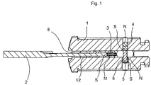
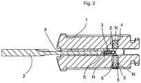
Fig. 1 ,2 eine schematische Schnittdarstellung durch den Zylinderkern mit eingeführtem Schlüssel bei geschlossener und offener Position des Sperrstiftes in magnetischer Ausführung -
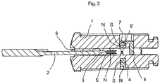
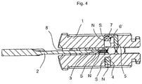
Fig. 3 ,4 eine abgewandelte magnetische Ausführung mit entsprechenden Positionen des Sperrstiftes.
-
Fig. 1 .2 a schematic sectional view through the cylinder core with inserted key in the closed and open position of the locking pin in a magnetic design -
Fig. 3 .4 a modified magnetic design with corresponding positions of the locking pin.
Bei allen dargestellten Ausführungen sind gleiche Teile mit den gleichen Bezugszeichen versehen.
So ist mit 1 der Zylinderkern bezeichnet, der in bekannter Weise in einem Schließzylindergehäuse drehbar gelagert ist. Auf die Darstellung dieses Gehäuses wurde hier verzichtet.
In dem Zylinderkern 1 befindet sich der Schlüsselkanal 8, in den der Schlüssel 2 einführbar ist.In all the illustrated embodiments, the same parts are provided with the same reference numerals.
Thus, denoted by 1 of the cylinder core, which is rotatably mounted in a known manner in a lock cylinder housing. On the presentation of this case was omitted here.
In the
Auch hierbei wurde die Darstellung vereinfacht, d. h. die üblichen Zuhaltungen 12 wurden nur angedeutet.Again, the presentation has been simplified, d. H. the
Der Kern der Erfindung liegt in dem Einsatz eines Sperrstiftes 5, der im Normalzustand - wenn sich kein Schlüssel in seinem Verschiebungsbereich oder Hubbereich befindet - soweit in den Schlüsselkanal 8 hineinragt, dass ein teilweise eingeführter Schlüssel an seinem weiteren Vorschub durch den Sperrstift gehindert wird. Bezogen auf den Längsschnitt durch den Zylinderkern ist der Sperrstift radial verschiebbar.The essence of the invention lies in the use of a
Bei der Ausführung nach den
Die Spitze oder der vordere Bereich des Schlüssels 2 ist ebenfalls mit einem Magneten versehen, der mit 3 bezeichnet ist.
Die Polung dieses Magneten 3 ist nun so, dass der mit dem Sperrstift 5 bewegliche Magnet 6 abgestoßen wird. Damit wird der Sperrstift in seine Bohrung zurück gedrückt und gibt den Schlüsselkanal 8 frei, so dass der Schlüssel 2 weiter in diesen eingeführt werden kann, bis er seine Endstellung erreicht, in der ein Schließvorgang ausführbar ist.The tip or the front portion of the
The polarity of this
Diese Wirkungsweise ist vergleichbar mit der bei der Ausführung nach den
Im Gegensatz zu dem ringförmigen Magneten 6 ist bei dieser Ausführung der Sperrstift mit einem L-förmigen Arm 7 versehen, der den Magneten 6' trägt.
Dieser Magnet ist dem Sperrstift damit vorgelagert, d. h. der Schlüssel nähert sich mit seinem Magneten 3 erst dem Magneten 6' und dann dem Sperrstift 5.
Unter der Wirkung der Gleichausrichtung der Polung der Magneten 3 und 6' wird der Sperrstift 5 bewegt (
This magnet is upstream of the locking pin, ie the key approaches with its
Under the effect of the alignment of the polarity of the
Claims (6)
- A key/lock cylinder combination, with a cylinder core (1) rotatably mounted in the cylinder housing, which core has a keyway (8) for introducing a key (2), and wherein core and housing tumblers which cooperate with each other and with the key are provided in the cylinder core (1) and also in the cylinder housing, wherein at least one additional locking pin (5) is provided which in a locking position projects into the keyway (8) and thereby prevents full introduction of the key (2), and which is movable by a feature arranged in the key (2) into a release position which releases the keyway, characterised in that the feature arranged in the key is a magnet (3) and a differently poled - relative to the magnet in the key - magnet (6) is associated with the additional locking pin, a further magnet (4) is arranged in the cylinder core or cylinder housing, which further magnet is poled such that it holds the locking pin (5) in its locking position in the keyway until the magnet (3) in the key moves the locking pin out of the locking position counter to the action of the magnet (4) in the cylinder core or cylinder housing.
- A key/lock cylinder combination according to one of the preceding claims, characterised in that
the magnet (3) in the key has a magnetic field directed preceding the introduction movement of the key into the keyway. - A key/lock cylinder combination according to one of the preceding claims, characterised in that
the additional locking pin (5, 7) is L-shaped, the arm (7) starting from the locking pin, which arm does not project into the keyway (8), bears a magnet (6') which - in the direction of introduction of the key - spatially precedes the locking pin (5). - A key/lock cylinder combination according to one of the preceding claims, characterised in that
the additional locking pin (5) is displaceable transversely to the keyway in the cylinder core. - A key/lock cylinder combination according to one of the preceding claims, characterised in that
the additional locking pin (5) is spring-loaded. - A key/lock cylinder combination according to one of the preceding claims, characterised in that
the magnets are permanent magnets and/or electromagnets.
Applications Claiming Priority (2)
| Application Number | Priority Date | Filing Date | Title |
|---|---|---|---|
| DE102011013167 | 2011-02-25 | ||
| DE201110014797 DE102011014797B3 (en) | 2011-02-25 | 2011-03-21 | Key actuated lock cylinder has locking pin that is moved from locking position, when magnet provided in key is operated against action of magnet arranged at cylinder bore or cylinder housing |
Publications (2)
| Publication Number | Publication Date |
|---|---|
| EP2492421A1 EP2492421A1 (en) | 2012-08-29 |
| EP2492421B1 true EP2492421B1 (en) | 2017-08-16 |
Family
ID=45566471
Family Applications (1)
| Application Number | Title | Priority Date | Filing Date |
|---|---|---|---|
| EP11075140.1A Active EP2492421B1 (en) | 2011-02-25 | 2011-06-17 | Key and lock cylinder combination |
Country Status (2)
| Country | Link |
|---|---|
| EP (1) | EP2492421B1 (en) |
| DE (1) | DE102011014797B3 (en) |
Families Citing this family (5)
| Publication number | Priority date | Publication date | Assignee | Title |
|---|---|---|---|---|
| WO2014096442A2 (en) * | 2012-12-23 | 2014-06-26 | Certaflex Bv | Cylinder lock and combination of such a lock and key |
| DE102013017117B4 (en) * | 2013-10-10 | 2017-05-11 | Assa Abloy Sicherheitstechnik Gmbh | Locking cylinder key system |
| DE102014005690B4 (en) * | 2014-04-14 | 2016-10-06 | Assa Abloy Sicherheitstechnik Gmbh | Lock and key system |
| FR3092856B1 (en) | 2019-02-20 | 2021-03-05 | Assa Abloy France Sas | Magnet control lock |
| EP4711562A1 (en) | 2024-09-13 | 2026-03-18 | ASSA ABLOY Opening Solutions Bulgaria EOOD | Lock cylinder and key |
Citations (3)
| Publication number | Priority date | Publication date | Assignee | Title |
|---|---|---|---|---|
| AT365712B (en) * | 1980-09-25 | 1982-02-10 | Evva Werke | MAGNETIC KEY |
| AT371532B (en) * | 1978-12-15 | 1983-07-11 | Grundmann Gmbh Geb | FLAT KEY |
| EP0812971A2 (en) * | 1996-06-13 | 1997-12-17 | EVVA - Werk Spezialerzeugung von Zylinder-und Sicherheitsschlössern Gesellschaft m.b.H. & Co. Kommanditgesellschaft | Flat key for cylinder lock |
Family Cites Families (13)
| Publication number | Priority date | Publication date | Assignee | Title |
|---|---|---|---|---|
| US3512382A (en) * | 1968-04-17 | 1970-05-19 | Liquidonics Inc | Hybrid lock |
| US3494157A (en) * | 1968-08-01 | 1970-02-10 | Ilco Corp | Magnetic lock |
| DE2344473B2 (en) * | 1973-09-04 | 1976-04-29 | Josef Voss KG, 5040 Brühl | CYLINDER CORE IN A CYLINDER LOCK WITH FLAT KEY |
| AT371533B (en) * | 1978-01-05 | 1983-07-11 | Grundmann Gmbh Geb | TURN CYLINDER LOCK |
| US4229959A (en) * | 1979-03-30 | 1980-10-28 | Easley Thomas E | Method and apparatus for opening a lock |
| DE3503660A1 (en) * | 1985-02-04 | 1986-08-07 | Fa. Wilhelm Karrenberg, 5620 Velbert | Locking device with locking cylinder and flat key |
| DE19527200A1 (en) * | 1995-07-26 | 1997-01-30 | Niederdrenk Julius Kg | Lock cylinder with pin tumblers and key for a lock cylinder with pin tumblers |
| DE29708308U1 (en) * | 1996-12-23 | 1997-08-28 | C. Ed. Schulte GmbH Zylinderschloßfabrik, 42551 Velbert | Locking cylinder |
| DE19732450B4 (en) * | 1997-07-24 | 2012-01-12 | C.Ed. Schulte Gesellschaft mit beschränkter Haftung Zylinderschlossfabrik | Reversible key lock cylinder |
| DE10000528A1 (en) * | 2000-01-08 | 2001-07-12 | Wilka Schliestechnik Gmbh | Lock cylinder has an extension pin shrouded by a rib in the channel which shifts the pin holders into the rotary setting on insertion of the correct key for increased security |
| DE102004021580B3 (en) * | 2004-05-03 | 2005-11-10 | Wilka Schließtechnik GmbH | From key and lock cylinder existing closing device |
| ES1064119Y (en) * | 2006-11-13 | 2007-05-01 | Tecnolar S L | FLAT SECURITY WRENCH, UNCOPIABLE |
| US8312749B2 (en) * | 2009-09-02 | 2012-11-20 | GMS Industries, Inc. | Lock and key mechanism and method of use |
-
2011
- 2011-03-21 DE DE201110014797 patent/DE102011014797B3/en not_active Expired - Fee Related
- 2011-06-17 EP EP11075140.1A patent/EP2492421B1/en active Active
Patent Citations (3)
| Publication number | Priority date | Publication date | Assignee | Title |
|---|---|---|---|---|
| AT371532B (en) * | 1978-12-15 | 1983-07-11 | Grundmann Gmbh Geb | FLAT KEY |
| AT365712B (en) * | 1980-09-25 | 1982-02-10 | Evva Werke | MAGNETIC KEY |
| EP0812971A2 (en) * | 1996-06-13 | 1997-12-17 | EVVA - Werk Spezialerzeugung von Zylinder-und Sicherheitsschlössern Gesellschaft m.b.H. & Co. Kommanditgesellschaft | Flat key for cylinder lock |
Also Published As
| Publication number | Publication date |
|---|---|
| EP2492421A1 (en) | 2012-08-29 |
| DE102011014797B3 (en) | 2012-03-01 |
Similar Documents
| Publication | Publication Date | Title |
|---|---|---|
| DE1918969A1 (en) | Mixed construction lock | |
| EP3153648B1 (en) | Padlock | |
| EP2870310B1 (en) | Lock cylinder key system | |
| DE3838481A1 (en) | CYLINDER LOCK | |
| EP2492421B1 (en) | Key and lock cylinder combination | |
| EP2868846B1 (en) | Padlock | |
| DE10333211B4 (en) | lock cylinder | |
| EP3561203B1 (en) | Padlock for securing a switch | |
| EP3517713B1 (en) | Closing device | |
| DE3037959A1 (en) | MOTOR VEHICLE LOCK | |
| DE2743769A1 (en) | LOCK AND CODED KEY TO OPERATE THE LOCK | |
| EP1931843B1 (en) | Locking device | |
| DE102006024063B4 (en) | Lock with a lockable by an electrically operated locking pin lock cylinder | |
| DE10329414B4 (en) | closing device | |
| EP0644974B1 (en) | Locking system composed of a lock and several keys | |
| DE102017125762A1 (en) | Closing unit for a motor vehicle | |
| EP1785558B1 (en) | Lock, in particular for safe | |
| DE102005026930B4 (en) | padlock | |
| DE102016004835B4 (en) | safety switch | |
| EP1482108B1 (en) | Key and lock combination with a copy protected profiled flat key | |
| WO2013044905A1 (en) | Locking cylinder-key system | |
| AT505825A2 (en) | PROCEDURE FOR THE PROTECTION OF A LOCK TO UNAUTHORIZED OPENING | |
| WO1997008412A1 (en) | Lock with a closing function released by inserting a card with magnetised areas | |
| EP0222135A1 (en) | Safety lock with flat key and piston tumblers | |
| DE102005000029A1 (en) | lock cylinder |
Legal Events
| Date | Code | Title | Description |
|---|---|---|---|
| PUAI | Public reference made under article 153(3) epc to a published international application that has entered the european phase |
Free format text: ORIGINAL CODE: 0009012 |
|
| AK | Designated contracting states |
Kind code of ref document: A1 Designated state(s): AL AT BE BG CH CY CZ DE DK EE ES FI FR GB GR HR HU IE IS IT LI LT LU LV MC MK MT NL NO PL PT RO RS SE SI SK SM TR |
|
| AX | Request for extension of the european patent |
Extension state: BA ME |
|
| 17P | Request for examination filed |
Effective date: 20130227 |
|
| 17Q | First examination report despatched |
Effective date: 20160804 |
|
| GRAP | Despatch of communication of intention to grant a patent |
Free format text: ORIGINAL CODE: EPIDOSNIGR1 |
|
| INTG | Intention to grant announced |
Effective date: 20170406 |
|
| GRAS | Grant fee paid |
Free format text: ORIGINAL CODE: EPIDOSNIGR3 |
|
| GRAA | (expected) grant |
Free format text: ORIGINAL CODE: 0009210 |
|
| AK | Designated contracting states |
Kind code of ref document: B1 Designated state(s): AL AT BE BG CH CY CZ DE DK EE ES FI FR GB GR HR HU IE IS IT LI LT LU LV MC MK MT NL NO PL PT RO RS SE SI SK SM TR |
|
| REG | Reference to a national code |
Ref country code: GB Ref legal event code: FG4D Free format text: NOT ENGLISH |
|
| REG | Reference to a national code |
Ref country code: CH Ref legal event code: EP |
|
| REG | Reference to a national code |
Ref country code: IE Ref legal event code: FG4D Free format text: LANGUAGE OF EP DOCUMENT: GERMAN |
|
| REG | Reference to a national code |
Ref country code: AT Ref legal event code: REF Ref document number: 919191 Country of ref document: AT Kind code of ref document: T Effective date: 20170915 |
|
| REG | Reference to a national code |
Ref country code: DE Ref legal event code: R096 Ref document number: 502011012785 Country of ref document: DE |
|
| REG | Reference to a national code |
Ref country code: CH Ref legal event code: NV Representative=s name: E. BLUM AND CO. AG PATENT- UND MARKENANWAELTE , CH |
|
| REG | Reference to a national code |
Ref country code: NL Ref legal event code: MP Effective date: 20170816 |
|
| REG | Reference to a national code |
Ref country code: LT Ref legal event code: MG4D |
|
| PG25 | Lapsed in a contracting state [announced via postgrant information from national office to epo] |
Ref country code: SE Free format text: LAPSE BECAUSE OF FAILURE TO SUBMIT A TRANSLATION OF THE DESCRIPTION OR TO PAY THE FEE WITHIN THE PRESCRIBED TIME-LIMIT Effective date: 20170816 Ref country code: FI Free format text: LAPSE BECAUSE OF FAILURE TO SUBMIT A TRANSLATION OF THE DESCRIPTION OR TO PAY THE FEE WITHIN THE PRESCRIBED TIME-LIMIT Effective date: 20170816 Ref country code: NL Free format text: LAPSE BECAUSE OF FAILURE TO SUBMIT A TRANSLATION OF THE DESCRIPTION OR TO PAY THE FEE WITHIN THE PRESCRIBED TIME-LIMIT Effective date: 20170816 Ref country code: LT Free format text: LAPSE BECAUSE OF FAILURE TO SUBMIT A TRANSLATION OF THE DESCRIPTION OR TO PAY THE FEE WITHIN THE PRESCRIBED TIME-LIMIT Effective date: 20170816 Ref country code: NO Free format text: LAPSE BECAUSE OF FAILURE TO SUBMIT A TRANSLATION OF THE DESCRIPTION OR TO PAY THE FEE WITHIN THE PRESCRIBED TIME-LIMIT Effective date: 20171116 |
|
| PG25 | Lapsed in a contracting state [announced via postgrant information from national office to epo] |
Ref country code: RS Free format text: LAPSE BECAUSE OF FAILURE TO SUBMIT A TRANSLATION OF THE DESCRIPTION OR TO PAY THE FEE WITHIN THE PRESCRIBED TIME-LIMIT Effective date: 20170816 Ref country code: LV Free format text: LAPSE BECAUSE OF FAILURE TO SUBMIT A TRANSLATION OF THE DESCRIPTION OR TO PAY THE FEE WITHIN THE PRESCRIBED TIME-LIMIT Effective date: 20170816 Ref country code: GR Free format text: LAPSE BECAUSE OF FAILURE TO SUBMIT A TRANSLATION OF THE DESCRIPTION OR TO PAY THE FEE WITHIN THE PRESCRIBED TIME-LIMIT Effective date: 20171117 Ref country code: BG Free format text: LAPSE BECAUSE OF FAILURE TO SUBMIT A TRANSLATION OF THE DESCRIPTION OR TO PAY THE FEE WITHIN THE PRESCRIBED TIME-LIMIT Effective date: 20171116 Ref country code: IS Free format text: LAPSE BECAUSE OF FAILURE TO SUBMIT A TRANSLATION OF THE DESCRIPTION OR TO PAY THE FEE WITHIN THE PRESCRIBED TIME-LIMIT Effective date: 20171216 Ref country code: ES Free format text: LAPSE BECAUSE OF FAILURE TO SUBMIT A TRANSLATION OF THE DESCRIPTION OR TO PAY THE FEE WITHIN THE PRESCRIBED TIME-LIMIT Effective date: 20170816 Ref country code: PL Free format text: LAPSE BECAUSE OF FAILURE TO SUBMIT A TRANSLATION OF THE DESCRIPTION OR TO PAY THE FEE WITHIN THE PRESCRIBED TIME-LIMIT Effective date: 20170816 |
|
| PG25 | Lapsed in a contracting state [announced via postgrant information from national office to epo] |
Ref country code: DK Free format text: LAPSE BECAUSE OF FAILURE TO SUBMIT A TRANSLATION OF THE DESCRIPTION OR TO PAY THE FEE WITHIN THE PRESCRIBED TIME-LIMIT Effective date: 20170816 Ref country code: CZ Free format text: LAPSE BECAUSE OF FAILURE TO SUBMIT A TRANSLATION OF THE DESCRIPTION OR TO PAY THE FEE WITHIN THE PRESCRIBED TIME-LIMIT Effective date: 20170816 Ref country code: RO Free format text: LAPSE BECAUSE OF FAILURE TO SUBMIT A TRANSLATION OF THE DESCRIPTION OR TO PAY THE FEE WITHIN THE PRESCRIBED TIME-LIMIT Effective date: 20170816 |
|
| REG | Reference to a national code |
Ref country code: DE Ref legal event code: R097 Ref document number: 502011012785 Country of ref document: DE |
|
| PG25 | Lapsed in a contracting state [announced via postgrant information from national office to epo] |
Ref country code: EE Free format text: LAPSE BECAUSE OF FAILURE TO SUBMIT A TRANSLATION OF THE DESCRIPTION OR TO PAY THE FEE WITHIN THE PRESCRIBED TIME-LIMIT Effective date: 20170816 Ref country code: IT Free format text: LAPSE BECAUSE OF FAILURE TO SUBMIT A TRANSLATION OF THE DESCRIPTION OR TO PAY THE FEE WITHIN THE PRESCRIBED TIME-LIMIT Effective date: 20170816 Ref country code: SK Free format text: LAPSE BECAUSE OF FAILURE TO SUBMIT A TRANSLATION OF THE DESCRIPTION OR TO PAY THE FEE WITHIN THE PRESCRIBED TIME-LIMIT Effective date: 20170816 Ref country code: SM Free format text: LAPSE BECAUSE OF FAILURE TO SUBMIT A TRANSLATION OF THE DESCRIPTION OR TO PAY THE FEE WITHIN THE PRESCRIBED TIME-LIMIT Effective date: 20170816 |
|
| PLBE | No opposition filed within time limit |
Free format text: ORIGINAL CODE: 0009261 |
|
| STAA | Information on the status of an ep patent application or granted ep patent |
Free format text: STATUS: NO OPPOSITION FILED WITHIN TIME LIMIT |
|
| 26N | No opposition filed |
Effective date: 20180517 |
|
| PG25 | Lapsed in a contracting state [announced via postgrant information from national office to epo] |
Ref country code: SI Free format text: LAPSE BECAUSE OF FAILURE TO SUBMIT A TRANSLATION OF THE DESCRIPTION OR TO PAY THE FEE WITHIN THE PRESCRIBED TIME-LIMIT Effective date: 20170816 |
|
| PG25 | Lapsed in a contracting state [announced via postgrant information from national office to epo] |
Ref country code: MT Free format text: LAPSE BECAUSE OF FAILURE TO SUBMIT A TRANSLATION OF THE DESCRIPTION OR TO PAY THE FEE WITHIN THE PRESCRIBED TIME-LIMIT Effective date: 20170816 |
|
| GBPC | Gb: european patent ceased through non-payment of renewal fee |
Effective date: 20180617 |
|
| REG | Reference to a national code |
Ref country code: BE Ref legal event code: MM Effective date: 20180630 |
|
| REG | Reference to a national code |
Ref country code: IE Ref legal event code: MM4A |
|
| PG25 | Lapsed in a contracting state [announced via postgrant information from national office to epo] |
Ref country code: LU Free format text: LAPSE BECAUSE OF NON-PAYMENT OF DUE FEES Effective date: 20180617 Ref country code: MC Free format text: LAPSE BECAUSE OF FAILURE TO SUBMIT A TRANSLATION OF THE DESCRIPTION OR TO PAY THE FEE WITHIN THE PRESCRIBED TIME-LIMIT Effective date: 20170816 |
|
| PG25 | Lapsed in a contracting state [announced via postgrant information from national office to epo] |
Ref country code: GB Free format text: LAPSE BECAUSE OF NON-PAYMENT OF DUE FEES Effective date: 20180617 Ref country code: IE Free format text: LAPSE BECAUSE OF NON-PAYMENT OF DUE FEES Effective date: 20180617 Ref country code: FR Free format text: LAPSE BECAUSE OF NON-PAYMENT OF DUE FEES Effective date: 20180630 |
|
| PG25 | Lapsed in a contracting state [announced via postgrant information from national office to epo] |
Ref country code: BE Free format text: LAPSE BECAUSE OF NON-PAYMENT OF DUE FEES Effective date: 20180630 |
|
| PG25 | Lapsed in a contracting state [announced via postgrant information from national office to epo] |
Ref country code: TR Free format text: LAPSE BECAUSE OF FAILURE TO SUBMIT A TRANSLATION OF THE DESCRIPTION OR TO PAY THE FEE WITHIN THE PRESCRIBED TIME-LIMIT Effective date: 20170816 |
|
| PG25 | Lapsed in a contracting state [announced via postgrant information from national office to epo] |
Ref country code: HU Free format text: LAPSE BECAUSE OF FAILURE TO SUBMIT A TRANSLATION OF THE DESCRIPTION OR TO PAY THE FEE WITHIN THE PRESCRIBED TIME-LIMIT; INVALID AB INITIO Effective date: 20110617 Ref country code: PT Free format text: LAPSE BECAUSE OF FAILURE TO SUBMIT A TRANSLATION OF THE DESCRIPTION OR TO PAY THE FEE WITHIN THE PRESCRIBED TIME-LIMIT Effective date: 20170816 |
|
| PG25 | Lapsed in a contracting state [announced via postgrant information from national office to epo] |
Ref country code: CY Free format text: LAPSE BECAUSE OF FAILURE TO SUBMIT A TRANSLATION OF THE DESCRIPTION OR TO PAY THE FEE WITHIN THE PRESCRIBED TIME-LIMIT Effective date: 20170816 Ref country code: MK Free format text: LAPSE BECAUSE OF NON-PAYMENT OF DUE FEES Effective date: 20170816 Ref country code: HR Free format text: LAPSE BECAUSE OF FAILURE TO SUBMIT A TRANSLATION OF THE DESCRIPTION OR TO PAY THE FEE WITHIN THE PRESCRIBED TIME-LIMIT Effective date: 20170816 |
|
| PG25 | Lapsed in a contracting state [announced via postgrant information from national office to epo] |
Ref country code: AL Free format text: LAPSE BECAUSE OF FAILURE TO SUBMIT A TRANSLATION OF THE DESCRIPTION OR TO PAY THE FEE WITHIN THE PRESCRIBED TIME-LIMIT Effective date: 20170816 |
|
| PGFP | Annual fee paid to national office [announced via postgrant information from national office to epo] |
Ref country code: AT Payment date: 20230525 Year of fee payment: 13 |
|
| PGFP | Annual fee paid to national office [announced via postgrant information from national office to epo] |
Ref country code: CH Payment date: 20230702 Year of fee payment: 13 |
|
| PGFP | Annual fee paid to national office [announced via postgrant information from national office to epo] |
Ref country code: DE Payment date: 20240507 Year of fee payment: 14 |
|
| REG | Reference to a national code |
Ref country code: CH Ref legal event code: PL |
|
| REG | Reference to a national code |
Ref country code: AT Ref legal event code: MM01 Ref document number: 919191 Country of ref document: AT Kind code of ref document: T Effective date: 20240617 |
|
| PG25 | Lapsed in a contracting state [announced via postgrant information from national office to epo] |
Ref country code: AT Free format text: LAPSE BECAUSE OF NON-PAYMENT OF DUE FEES Effective date: 20240617 Ref country code: CH Free format text: LAPSE BECAUSE OF NON-PAYMENT OF DUE FEES Effective date: 20240630 |
|
| REG | Reference to a national code |
Ref country code: DE Ref legal event code: R119 Ref document number: 502011012785 Country of ref document: DE |
|
| PG25 | Lapsed in a contracting state [announced via postgrant information from national office to epo] |
Ref country code: DE Free format text: LAPSE BECAUSE OF NON-PAYMENT OF DUE FEES Effective date: 20260101 |