EP2492589B1 - Dispositif d'éclairage doté d'un dissipateur de chaleur - Google Patents
Dispositif d'éclairage doté d'un dissipateur de chaleur Download PDFInfo
- Publication number
- EP2492589B1 EP2492589B1 EP12155711.0A EP12155711A EP2492589B1 EP 2492589 B1 EP2492589 B1 EP 2492589B1 EP 12155711 A EP12155711 A EP 12155711A EP 2492589 B1 EP2492589 B1 EP 2492589B1
- Authority
- EP
- European Patent Office
- Prior art keywords
- housing
- previous
- illumination device
- end wall
- heat
- Prior art date
- Legal status (The legal status is an assumption and is not a legal conclusion. Google has not performed a legal analysis and makes no representation as to the accuracy of the status listed.)
- Active
Links
Images


Classifications
-
- F—MECHANICAL ENGINEERING; LIGHTING; HEATING; WEAPONS; BLASTING
- F21—LIGHTING
- F21V—FUNCTIONAL FEATURES OR DETAILS OF LIGHTING DEVICES OR SYSTEMS THEREOF; STRUCTURAL COMBINATIONS OF LIGHTING DEVICES WITH OTHER ARTICLES, NOT OTHERWISE PROVIDED FOR
- F21V29/00—Protecting lighting devices from thermal damage; Cooling or heating arrangements specially adapted for lighting devices or systems
-
- F—MECHANICAL ENGINEERING; LIGHTING; HEATING; WEAPONS; BLASTING
- F21—LIGHTING
- F21K—NON-ELECTRIC LIGHT SOURCES USING LUMINESCENCE; LIGHT SOURCES USING ELECTROCHEMILUMINESCENCE; LIGHT SOURCES USING CHARGES OF COMBUSTIBLE MATERIAL; LIGHT SOURCES USING SEMICONDUCTOR DEVICES AS LIGHT-GENERATING ELEMENTS; LIGHT SOURCES NOT OTHERWISE PROVIDED FOR
- F21K9/00—Light sources using semiconductor devices as light-generating elements, e.g. using light-emitting diodes [LED] or lasers
-
- F—MECHANICAL ENGINEERING; LIGHTING; HEATING; WEAPONS; BLASTING
- F21—LIGHTING
- F21V—FUNCTIONAL FEATURES OR DETAILS OF LIGHTING DEVICES OR SYSTEMS THEREOF; STRUCTURAL COMBINATIONS OF LIGHTING DEVICES WITH OTHER ARTICLES, NOT OTHERWISE PROVIDED FOR
- F21V29/00—Protecting lighting devices from thermal damage; Cooling or heating arrangements specially adapted for lighting devices or systems
- F21V29/50—Cooling arrangements
- F21V29/70—Cooling arrangements characterised by passive heat-dissipating elements, e.g. heat-sinks
- F21V29/71—Cooling arrangements characterised by passive heat-dissipating elements, e.g. heat-sinks using a combination of separate elements interconnected by heat-conducting means, e.g. with heat pipes or thermally conductive bars between separate heat-sink elements
-
- F—MECHANICAL ENGINEERING; LIGHTING; HEATING; WEAPONS; BLASTING
- F21—LIGHTING
- F21V—FUNCTIONAL FEATURES OR DETAILS OF LIGHTING DEVICES OR SYSTEMS THEREOF; STRUCTURAL COMBINATIONS OF LIGHTING DEVICES WITH OTHER ARTICLES, NOT OTHERWISE PROVIDED FOR
- F21V29/00—Protecting lighting devices from thermal damage; Cooling or heating arrangements specially adapted for lighting devices or systems
- F21V29/50—Cooling arrangements
- F21V29/70—Cooling arrangements characterised by passive heat-dissipating elements, e.g. heat-sinks
- F21V29/74—Cooling arrangements characterised by passive heat-dissipating elements, e.g. heat-sinks with fins or blades
-
- F—MECHANICAL ENGINEERING; LIGHTING; HEATING; WEAPONS; BLASTING
- F21—LIGHTING
- F21V—FUNCTIONAL FEATURES OR DETAILS OF LIGHTING DEVICES OR SYSTEMS THEREOF; STRUCTURAL COMBINATIONS OF LIGHTING DEVICES WITH OTHER ARTICLES, NOT OTHERWISE PROVIDED FOR
- F21V29/00—Protecting lighting devices from thermal damage; Cooling or heating arrangements specially adapted for lighting devices or systems
- F21V29/50—Cooling arrangements
- F21V29/70—Cooling arrangements characterised by passive heat-dissipating elements, e.g. heat-sinks
- F21V29/74—Cooling arrangements characterised by passive heat-dissipating elements, e.g. heat-sinks with fins or blades
- F21V29/77—Cooling arrangements characterised by passive heat-dissipating elements, e.g. heat-sinks with fins or blades with essentially identical diverging planar fins or blades, e.g. with fan-like or star-like cross-section
- F21V29/773—Cooling arrangements characterised by passive heat-dissipating elements, e.g. heat-sinks with fins or blades with essentially identical diverging planar fins or blades, e.g. with fan-like or star-like cross-section the planes containing the fins or blades having the direction of the light emitting axis
-
- F—MECHANICAL ENGINEERING; LIGHTING; HEATING; WEAPONS; BLASTING
- F21—LIGHTING
- F21V—FUNCTIONAL FEATURES OR DETAILS OF LIGHTING DEVICES OR SYSTEMS THEREOF; STRUCTURAL COMBINATIONS OF LIGHTING DEVICES WITH OTHER ARTICLES, NOT OTHERWISE PROVIDED FOR
- F21V29/00—Protecting lighting devices from thermal damage; Cooling or heating arrangements specially adapted for lighting devices or systems
- F21V29/50—Cooling arrangements
- F21V29/70—Cooling arrangements characterised by passive heat-dissipating elements, e.g. heat-sinks
- F21V29/80—Cooling arrangements characterised by passive heat-dissipating elements, e.g. heat-sinks with pins or wires
-
- F—MECHANICAL ENGINEERING; LIGHTING; HEATING; WEAPONS; BLASTING
- F21—LIGHTING
- F21V—FUNCTIONAL FEATURES OR DETAILS OF LIGHTING DEVICES OR SYSTEMS THEREOF; STRUCTURAL COMBINATIONS OF LIGHTING DEVICES WITH OTHER ARTICLES, NOT OTHERWISE PROVIDED FOR
- F21V29/00—Protecting lighting devices from thermal damage; Cooling or heating arrangements specially adapted for lighting devices or systems
- F21V29/50—Cooling arrangements
- F21V29/70—Cooling arrangements characterised by passive heat-dissipating elements, e.g. heat-sinks
- F21V29/83—Cooling arrangements characterised by passive heat-dissipating elements, e.g. heat-sinks the elements having apertures, ducts or channels, e.g. heat radiation holes
Definitions
- the invention relates to a lighting device according to the preamble of claim 1.
- a luminaire with a thermally conductive conical housing body and a recorded therein flat insert with LEDs known.
- a reflector is placed around the LEDs on the insert.
- the housing body has radially inwardly projecting ribs forming a central passageway. At one end, the rib picks up the insert with the LEDs. Heat is dissipated mainly by dissipating heat to the air in the central passage and between the fins.
- the object of the invention is to propose a lighting device which does not have the disadvantages of the prior art. In particular, should be done by means of natural convection effective cooling of the lighting device.
- the object is achieved by a lighting device according to the characterizing part of claim 1.
- One of the advantages of the invention is that the heat loss of the light source is dissipated on the one hand via the cams to the housing and on the other hand to air flowing through the channels.
- the chimney-like design of the housing causes a reinforcement of the air flow or convection, which is also here is called chimney effect. This cooling effect is supported by the fact that heat loss is transmitted directly to the housing in the area of the adjacent creeks.
- Another advantage of the invention is that the inventive design of the lighting device in different positions or positions is effective because a congestion of air is prevented by the chimney effect acts not only in the longitudinal direction of the housing but also in the front and rear of the housing.
- the lighting means is designed as an LED module with at least one LED and fixed to the end wall.
- One of the advantages of the invention is that a light source with a long life and advantageous light properties in a particularly compact design with the acting as a carrier module end wall of the heat spreader is directly connected.
- a plurality of heat-distributing elements which are designed as cooling pins and / or cooling ribs, are arranged on the end wall opposite to the lighting means.
- One of the advantages of the invention is that lamp-specific, a corresponding heat spreader can be selected or produced, wherein cooling pins and / or cooling fins enhance the heat distribution to the ambient air.
- the end wall has at least one radially inwardly directed channel which opens into at least one orifice in the end wall, the mouth preferably being arranged approximately centrally in the end wall.
- One of the advantages of the invention is that the removal of heat loss by air thereby improves and the formation of heat build-up is prevented.
- the reflector protrudes into the trough and / or the reflector projects at least partially into the housing.
- the lighting device can be realized in a compact design, wherein the cooling of the lamp or the dissipation of heat loss is still efficient.
- the chimney effect described is always guaranteed.
- each cam has a width b which is related to an imaginary outer mean diameter D of the trough such that effective heat loss of the luminous means can be dissipated via the cams to the housing and to air flowing through the channels so that both effects are advantageously combined.
- the jacket and / or the end wall is perforated at least in places.
- One of the advantages of the invention is that increased convection can be achieved by means of bores, holes.
- the housing is connected by pressing and / or joining and / or Kaltdehn- and / or Eindehn- and / or adhesive bond with the heat spreader.
- One of the advantages of the invention is that in particular the heat transfer from the heat spreader to the housing is increased by said type of connection.
- the reflector has a light exit opening whose outer opening edge is at least locally spaced from the housing.
- One of the advantages of the invention is that the natural air flow in the housing is conveyed in different fastening positions of the lighting device by inflow and / or outflow of air.
- the heat spreader made of light metal, in particular aluminum, is formed.
- the heat spreader with trough, cam and / or réelleverfeilettin can be produced by die-casting. A reworking of the die-cast heat spreader, in particular the end wall, cams, bores and / or heat-conducting elements is possible with known processing methods.
- the heat spreader can also be subsequently surface treated for improved heat conduction.
- the housing can be formed of a metal or non-metallic material, so that a broad design freedom in the choice of housing shapes and / or housing materials is possible, always ensuring effective heat dissipation by means of the heat spreader.
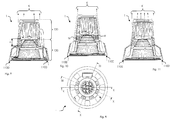
- FIG. 1 1 illustrates an exploded, simplified illustration of a half section of the lighting device 1 according to the invention, with a lighting means 40, a heat distributor 20 connected thereto, a housing 10 connected to the heat distributor 20 and a reflector 30.
- the heat spreader 20 preferably has a trough 201 with a jacket 203 and an end wall 205, wherein the light source 40 bears against the end wall 205.
- the jacket 203 and / or the end wall 205 may be broken at least in places.
- the heat spreader 20 can also be designed as a support wall 205 with cams 207 arranged on it.
- the support wall 205, or end wall can be offset from holes which form the channels 209, in order to allow good ventilation.
- the light-emitting means 40 mounted on the support wall conducts its heat loss to the support wall 205. Due to the thermal coupling of the support wall via the cams to the housing 10, this heat loss is at least partially released to the housing. Another part of the heat loss is given by convection to the ambient air.
- the shell 203 of the trough 201 has two mutually remote shell ends 2031,2032 and outwardly projecting cams 207, wherein between the cam 207 continuous from one to the other shell end 2031,2032 extending channels 209 are present.
- the housing 10 In the assembled state of the lighting device, which is also referred to as a light, the housing 10 abuts against the cam 207.
- the contact surfaces are simplified and not to scale denoted by reference numeral 11.
- the heat loss of the light source 40 is dissipated on the one hand via the cam 207 to the housing 10 and on the other hand to the air flowing through the channels 209.
- the chimney-like configuration of the housing 10 causes an amplification of the air flow or convection. This cooling effect is assisted by the fact that heat loss is transmitted directly to the housing 10 in the region of the abutment surfaces 11.
- the light-emitting means 40 is preferably designed as an LED module with at least one LED and attached to the end wall 205.
- heat conduction such as thermal grease, an effective heat transfer from the lamp to the heat spreader 20 can be achieved.
- FIG. 2 illustrates the heat spreader 20 with arranged thereon illuminant 40 of the inventive lighting device 1 in a plan view.
- Each cam 207 has a width b, which is to an imaginary outer average diameter D of the trough 201 in the ratio of 1/64 to 1/4, preferably in the ratio of 1/32 to 1/8, particularly preferably in the ratio 1/16 ,
- the part of the housing on which the cams 207 abut, may be parallel or inclined to a central axis, not shown, of the housing.
- FIG. 3 Illustrated shows a longitudinal section of the heat spreader along the in FIG. 2 illustrated section line III-III.
- the sheath 203 and / or the end wall 205 may be perforated at least in places to assist in convection.
- a plurality of heat distribution elements 211 which are designed as cooling pins and / or cooling ribs, can be arranged on the end wall 205, opposite the light source 40.
- the heat distribution elements 211 do not directly contact the housing 10, which can, however, be realized by suitable design measures.
- Reference numeral 2050 designates a channel, bore or opening.
- the end wall 205 has at least one such radially inwardly directed channel 2050. This opens into an approximately central mouth 2051 in the end wall 205 to improve the dissipation of heat loss by air. This prevents heat accumulation on the bottom of the end wall and promotes convection.
- Reference numerals 2031 and 2032 designate mutually remote shell ends.
- FIGS. 4 illustrates a perspective view of the inventive lighting device 1, wherein the rear or rear part of the housing is shown broken off, so that the condimentableitopathy 211, which are formed as pins, are visible.
- the reference numeral 2050 designates a channel which opens into the approximately central mouth 2051.
- FIG. 5 illustrates a side view of a composite inventive lighting device 1, with a view of the housing 10.
- the shell of the housing 10 has a plurality of ventilation openings, which support the convection in the housing. Depending on the position of the lighting device, they serve as suction openings or inlet openings and / or outlet openings.
- FIGS. 6 and 7 illustrate a sectional view of a lighting device 1 according to the invention, wherein the elongated arrows K illustrate the natural convection and the wider arrows W heat transfer from the heat spreader 20 to the housing 10.
- the reflector 30 has a light exit opening 301, whose outer opening edge 303 is spaced at least in places from the housing 10, so that an opening, a gap or passage is present.
- a light exit opening 301 whose outer opening edge 303 is spaced at least in places from the housing 10, so that an opening, a gap or passage is present.
- FIG. 7 reference numeral 304 denotes a shutter which is disposed between the opening edge 303 of the reflector and the housing.
- the reflector has a reflector edge 305, in the outer region of the aperture 304 is arranged.
- the reflector edge 305 is also referred to as a collar or flange and may have a planar extension. Both the aperture 304, as well as the reflector edge 305 may at least in places as through holes, slots or the like formed openings, which serve to assist the ventilation of the housing and the dissipation of heat loss.
- FIG. 8 illustrates a plan view of the back of the inventive lighting device 1 with the respective section lines XX, XI-XI and XII-XII.
- FIGS. 9, 10 and 11 illustrate in simplified representation, each a half-section along the section lines of FIG. 8 the elongated arrows K illustrate the natural convection in and through the housing 10 and the wider arrows W heat transfer from the heat spreader 20 to the housing 10.
- openings 110 are present on the casing of the housing 10. These are, for example, designed as elongated or rectangular holes. As opening 110 also the front and rear opening on the housing 10 are understood.
- Reference numeral 1100 designates a gap or opening between the aperture of the reflector and the housing, which extends at least partially along the inner circumference of the housing in this area.
- the gap allows as shown that the designated by arrow K air can flow through this gap in the housing.
- n the length of a cam, that is cam length.
- the cam length of the inventive Lighting device can be related to the mean diameter D, which in FIG. 3 is shown.
- the ratio between n and D is in the range of 2/1 to 1/120, preferably in the range of 1 ⁇ 2 to 1/80, more preferably in the range of 1 ⁇ 2 to 1/10.
- the natural convection in the housing can be supported by an electrically operated, not shown fan.
- the fan can be temperature-controlled.
- the housing is divided into several parts or partial lateral surfaces - here in a rear part 120 and a front part 130.
- the respective parts are conical or designed as a blunt cone.
- the housing shape is not limited to this embodiment, but may consist of a conical part and / or a cylindrical part.
- the cross-sectional area with respect to a section perpendicular to the longitudinal axis of the housing may be round and / or polygonal.
- the cams may extend over the end wall into the region of the possibly existing heat dissipation elements.
- the cams may be formed as a part of the housing, wherein a portion of the cam at least in places on the rear housing part 120 and / or front housing part 130 bear or are connected thereto.
Landscapes
- Engineering & Computer Science (AREA)
- General Engineering & Computer Science (AREA)
- Physics & Mathematics (AREA)
- Microelectronics & Electronic Packaging (AREA)
- Optics & Photonics (AREA)
- Arrangement Of Elements, Cooling, Sealing, Or The Like Of Lighting Devices (AREA)
Claims (12)
- Dispositif d'éclairage (1) comprenant un moyen d'éclairage (40), un dissipateur thermique (20) associé à celui-ci, un boîtier (10) relié au dissipateur thermique (20) et un réflecteur (30), caractérisé en ce que
le dissipateur thermique (20) comprend une cuve (201) pourvue d'une enveloppe (203) et d'une paroi d'extrémité (205), le moyen d'éclairage (40) étant en appui sur la paroi d'extrémité (205),
le boîtier (203) de la cuve (201) comprend deux extrémités d'enveloppe (2031, 2032) opposées l'une à l'autre et des cames (207) saillants vers l'extérieur,
des canaux extensibles (209) qui s'étendent de bout en bout d'une extrémité d'enveloppe (2031, 2032) à l'autre sont ménagés entre les cames (207) et le boîtier (10) est en appui par le biais de surfaces de contact (11) sur les cames (207) du dissipateur thermique (20) pour dissiper les pertes de chaleur du moyen d'éclairage par le biais des cames au niveau du boîtier et de l'air qui s'écoule dans les canaux. - Dispositif d'éclairage (1) selon l'une des revendications précédentes, caractérisé en ce que le moyen d'éclairage (40) est configuré sous la forme d'un module de LED comprenant au moins une LED et est fixé à la paroi d'extrémité (205).
- Dispositif d'éclairage (1) selon l'une des revendications précédentes, caractérisé en ce que (40) plusieurs éléments de dissipation thermique (211), qui sont configurés sous la forme de tiges de refroidissement et/ou de nervures de refroidissement, sont disposés au niveau de la paroi d'extrémité (205) en face du dispositif d'éclairage.
- Dispositif d'éclairage (1) selon l'une des revendications précédentes, caractérisé en ce que la paroi d'extrémité (205) comporte au moins un canal (2050), dirigé radialement vers l'intérieur, qui débouche dans au moins un orifice (2051) ménagé dans la paroi d'extrémité (205) pour améliorer l'évacuation de pertes de chaleur par le biais de l'air.
- Dispositif d'éclairage (1) selon l'une des revendications précédentes, caractérisé en ce que le réflecteur (30) fait saillie dans la cuve (201).
- Dispositif d'éclairage (1) selon l'une des revendications précédentes, caractérisé en ce que le réflecteur (30) fait saillie au moins partiellement dans le boîtier (10).
- Dispositif d'éclairage (1) selon l'une des revendications précédentes, caractérisé en ce que chaque came (207) a une largeur b qui est dans un rapport de 1/64 à 1/4, de préférence dans un rapport de 1/32 à 1/8, de manière particulièrement préférée dans un rapport de 1/16, relativement à un diamètre moyen extérieure imaginaire D de la cuve (201).
- Dispositif d'éclairage (1) selon l'une des revendications précédentes, caractérisé en ce que le boîtier (203) et/ou la paroi d'extrémité (205) sont interrompu au moins par endroits.
- Dispositif d'éclairage (1) selon l'une des revendications précédentes, caractérisé en ce que le boîtier (10) est relié au dissipateur thermique (20) par une liaison par pressage et/ou assemblage et/ou étirage à froid et/ou compression et/ou collage.
- Dispositif d'éclairage (1) selon l'une des revendications précédentes, caractérisé en ce que le réflecteur (30) comporte une ouverture de sortie de lumière (301) dont le bord extérieur (303) est espacé au moins par endroits du boîtier (10) de telle sorte que le flux d'air naturel est transporté dans le boîtier (10) est acheminé par entrée ou sortie d'air.
- Dispositif d'éclairage (1) selon l'une des revendications précédentes, caractérisé en ce que le dissipateur thermique (20) est réalisé en métal léger, en particulier en aluminium.
- Dispositif d'éclairage (1) selon l'une des revendications précédentes, caractérisé en ce que le dissipateur thermique (20) peut être fabriqué par un procédé de moulage sous pression.
Applications Claiming Priority (1)
| Application Number | Priority Date | Filing Date | Title |
|---|---|---|---|
| CH00304/11A CH704544A1 (de) | 2011-02-22 | 2011-02-22 | Leuchteinrichtung mit Wärmeverteiler. |
Publications (2)
| Publication Number | Publication Date |
|---|---|
| EP2492589A1 EP2492589A1 (fr) | 2012-08-29 |
| EP2492589B1 true EP2492589B1 (fr) | 2016-04-27 |
Family
ID=44454010
Family Applications (1)
| Application Number | Title | Priority Date | Filing Date |
|---|---|---|---|
| EP12155711.0A Active EP2492589B1 (fr) | 2011-02-22 | 2012-02-16 | Dispositif d'éclairage doté d'un dissipateur de chaleur |
Country Status (2)
| Country | Link |
|---|---|
| EP (1) | EP2492589B1 (fr) |
| CH (1) | CH704544A1 (fr) |
Families Citing this family (4)
| Publication number | Priority date | Publication date | Assignee | Title |
|---|---|---|---|---|
| CN104180352B (zh) * | 2013-05-24 | 2017-06-06 | 深圳市海洋王照明工程有限公司 | 大功率灯具 |
| GB2517064B (en) * | 2013-06-14 | 2020-04-15 | Aurora Ltd | Improved lighting unit |
| WO2015133196A1 (fr) * | 2014-03-03 | 2015-09-11 | 株式会社アイ・ライティング・システム | Dispositif d'éclairage et unité de source de lumière à del |
| JP5897744B2 (ja) * | 2015-02-20 | 2016-03-30 | 株式会社アイ・ライティング・システム | 照明器具及びled光源ユニット |
Citations (2)
| Publication number | Priority date | Publication date | Assignee | Title |
|---|---|---|---|---|
| US20080186704A1 (en) * | 2006-08-11 | 2008-08-07 | Enertron, Inc. | LED Light in Sealed Fixture with Heat Transfer Agent |
| EP2180249A1 (fr) * | 2008-10-24 | 2010-04-28 | Hyundai Telecommunication Co., Ltd. | Projecteur de type DEL circulaire utilisant un nano-diffuseur |
Family Cites Families (5)
| Publication number | Priority date | Publication date | Assignee | Title |
|---|---|---|---|---|
| TWM332793U (en) * | 2007-11-28 | 2008-05-21 | Cooler Master Co Ltd | Heat radiating structure and the lighting apparatus |
| TWM334274U (en) * | 2007-12-04 | 2008-06-11 | Cooler Master Co Ltd | A lighting device and cover with heat conduction structure |
| WO2010066841A1 (fr) * | 2008-12-11 | 2010-06-17 | Ledned Holding B.V. | Système de lampe à del |
| DE202009000699U1 (de) | 2009-01-16 | 2009-03-26 | Rd System-Leuchten Ag | Leuchtmittelmodul mit einer LED-Bestückung |
| US8541931B2 (en) * | 2009-03-17 | 2013-09-24 | Intematix Corporation | LED based lamp including reflective hood to reduce variation in illuminance |
-
2011
- 2011-02-22 CH CH00304/11A patent/CH704544A1/de not_active Application Discontinuation
-
2012
- 2012-02-16 EP EP12155711.0A patent/EP2492589B1/fr active Active
Patent Citations (2)
| Publication number | Priority date | Publication date | Assignee | Title |
|---|---|---|---|---|
| US20080186704A1 (en) * | 2006-08-11 | 2008-08-07 | Enertron, Inc. | LED Light in Sealed Fixture with Heat Transfer Agent |
| EP2180249A1 (fr) * | 2008-10-24 | 2010-04-28 | Hyundai Telecommunication Co., Ltd. | Projecteur de type DEL circulaire utilisant un nano-diffuseur |
Also Published As
| Publication number | Publication date |
|---|---|
| EP2492589A1 (fr) | 2012-08-29 |
| CH704544A1 (de) | 2012-08-31 |
Similar Documents
| Publication | Publication Date | Title |
|---|---|---|
| EP2556296B1 (fr) | Boîtier de lampe | |
| DE102012222184A1 (de) | Leuchte mit Luftleitflächen | |
| EP2394096A1 (fr) | Corps de refroidissement pour un dispositif d'éclairage | |
| EP2492589B1 (fr) | Dispositif d'éclairage doté d'un dissipateur de chaleur | |
| WO2011054508A1 (fr) | Élément luminescent à led | |
| DE102010030296A1 (de) | Lampe | |
| EP2320137B1 (fr) | Corps de refroidissement pour lampe à DEL | |
| DE102011081369A1 (de) | Leuchte, insbesondere LED-Leuchte mit passiver Kühlung | |
| DE102009051334B4 (de) | LED-Lampe mit Kühlkörper | |
| EP2647907B1 (fr) | Élément d'éclairage avec réflecteur | |
| DE202008004795U1 (de) | Wohnraumleuchte | |
| EP3911892B1 (fr) | Luminaire avec dissipateur thermique fermé sur la périphérie | |
| DE202011000220U1 (de) | LED-Leuchte, insbesondere für Aquarien, Terrarien oder dergleichen | |
| DE202008000360U1 (de) | Leuchte mit einem Leuchtgehäuse in Form eines Hohlprofils | |
| DE102008004799A1 (de) | Rundumleuchte, vorzugsweise Rundumkennleuchte | |
| DE202006004833U1 (de) | Lampenreflektor mit Kühlkörper | |
| DE102009060725B4 (de) | Kühlsystem für eine LED-Hochleistungsstraßenbeleuchtung | |
| EP2530377B1 (fr) | Système de refroidissement pour lampe | |
| EP2710295B1 (fr) | Dispositif d'éclairage | |
| DE102010010649B4 (de) | Leuchte für die Raumbeleuchtung | |
| DE102010047158A1 (de) | Modul für eine Beleuchtungseinrichtung und Beleuchtungseinrichtung | |
| DE102013201955A1 (de) | Halbleiter-Leuchtvorrichtung mit Wärmerohr | |
| DE102008048909A1 (de) | Leuchte mit geschlossenem Leuchtengehäuse | |
| DE102014205471A1 (de) | Leuchte mit LED | |
| DE102008006535A1 (de) | Leuchte |
Legal Events
| Date | Code | Title | Description |
|---|---|---|---|
| PUAI | Public reference made under article 153(3) epc to a published international application that has entered the european phase |
Free format text: ORIGINAL CODE: 0009012 |
|
| AK | Designated contracting states |
Kind code of ref document: A1 Designated state(s): AL AT BE BG CH CY CZ DE DK EE ES FI FR GB GR HR HU IE IS IT LI LT LU LV MC MK MT NL NO PL PT RO RS SE SI SK SM TR |
|
| AX | Request for extension of the european patent |
Extension state: BA ME |
|
| 17P | Request for examination filed |
Effective date: 20130228 |
|
| REG | Reference to a national code |
Ref country code: DE Ref legal event code: R079 Ref document number: 502012006862 Country of ref document: DE Free format text: PREVIOUS MAIN CLASS: F21V0029000000 Ipc: F21V0029710000 |
|
| RIC1 | Information provided on ipc code assigned before grant |
Ipc: F21V 29/77 20150101ALI20151113BHEP Ipc: F21V 29/00 20150101ALI20151113BHEP Ipc: F21K 99/00 20100101ALI20151113BHEP Ipc: F21V 29/71 20150101AFI20151113BHEP Ipc: F21V 29/74 20150101ALI20151113BHEP Ipc: F21V 29/80 20150101ALI20151113BHEP |
|
| GRAP | Despatch of communication of intention to grant a patent |
Free format text: ORIGINAL CODE: EPIDOSNIGR1 |
|
| INTG | Intention to grant announced |
Effective date: 20160113 |
|
| GRAS | Grant fee paid |
Free format text: ORIGINAL CODE: EPIDOSNIGR3 |
|
| GRAA | (expected) grant |
Free format text: ORIGINAL CODE: 0009210 |
|
| AK | Designated contracting states |
Kind code of ref document: B1 Designated state(s): AL AT BE BG CH CY CZ DE DK EE ES FI FR GB GR HR HU IE IS IT LI LT LU LV MC MK MT NL NO PL PT RO RS SE SI SK SM TR |
|
| REG | Reference to a national code |
Ref country code: GB Ref legal event code: FG4D Free format text: NOT ENGLISH |
|
| REG | Reference to a national code |
Ref country code: CH Ref legal event code: EP |
|
| REG | Reference to a national code |
Ref country code: AT Ref legal event code: REF Ref document number: 795237 Country of ref document: AT Kind code of ref document: T Effective date: 20160515 |
|
| REG | Reference to a national code |
Ref country code: IE Ref legal event code: FG4D Free format text: LANGUAGE OF EP DOCUMENT: GERMAN |
|
| REG | Reference to a national code |
Ref country code: CH Ref legal event code: NV Representative=s name: BRAUNPAT BRAUN EDER AG, CH |
|
| REG | Reference to a national code |
Ref country code: DE Ref legal event code: R096 Ref document number: 502012006862 Country of ref document: DE |
|
| REG | Reference to a national code |
Ref country code: LT Ref legal event code: MG4D |
|
| REG | Reference to a national code |
Ref country code: NL Ref legal event code: MP Effective date: 20160427 |
|
| PG25 | Lapsed in a contracting state [announced via postgrant information from national office to epo] |
Ref country code: NL Free format text: LAPSE BECAUSE OF FAILURE TO SUBMIT A TRANSLATION OF THE DESCRIPTION OR TO PAY THE FEE WITHIN THE PRESCRIBED TIME-LIMIT Effective date: 20160427 |
|
| PG25 | Lapsed in a contracting state [announced via postgrant information from national office to epo] |
Ref country code: LT Free format text: LAPSE BECAUSE OF FAILURE TO SUBMIT A TRANSLATION OF THE DESCRIPTION OR TO PAY THE FEE WITHIN THE PRESCRIBED TIME-LIMIT Effective date: 20160427 Ref country code: PL Free format text: LAPSE BECAUSE OF FAILURE TO SUBMIT A TRANSLATION OF THE DESCRIPTION OR TO PAY THE FEE WITHIN THE PRESCRIBED TIME-LIMIT Effective date: 20160427 Ref country code: NO Free format text: LAPSE BECAUSE OF FAILURE TO SUBMIT A TRANSLATION OF THE DESCRIPTION OR TO PAY THE FEE WITHIN THE PRESCRIBED TIME-LIMIT Effective date: 20160727 Ref country code: FI Free format text: LAPSE BECAUSE OF FAILURE TO SUBMIT A TRANSLATION OF THE DESCRIPTION OR TO PAY THE FEE WITHIN THE PRESCRIBED TIME-LIMIT Effective date: 20160427 |
|
| PG25 | Lapsed in a contracting state [announced via postgrant information from national office to epo] |
Ref country code: HR Free format text: LAPSE BECAUSE OF FAILURE TO SUBMIT A TRANSLATION OF THE DESCRIPTION OR TO PAY THE FEE WITHIN THE PRESCRIBED TIME-LIMIT Effective date: 20160427 Ref country code: LV Free format text: LAPSE BECAUSE OF FAILURE TO SUBMIT A TRANSLATION OF THE DESCRIPTION OR TO PAY THE FEE WITHIN THE PRESCRIBED TIME-LIMIT Effective date: 20160427 Ref country code: SE Free format text: LAPSE BECAUSE OF FAILURE TO SUBMIT A TRANSLATION OF THE DESCRIPTION OR TO PAY THE FEE WITHIN THE PRESCRIBED TIME-LIMIT Effective date: 20160427 Ref country code: ES Free format text: LAPSE BECAUSE OF FAILURE TO SUBMIT A TRANSLATION OF THE DESCRIPTION OR TO PAY THE FEE WITHIN THE PRESCRIBED TIME-LIMIT Effective date: 20160427 Ref country code: RS Free format text: LAPSE BECAUSE OF FAILURE TO SUBMIT A TRANSLATION OF THE DESCRIPTION OR TO PAY THE FEE WITHIN THE PRESCRIBED TIME-LIMIT Effective date: 20160427 Ref country code: GR Free format text: LAPSE BECAUSE OF FAILURE TO SUBMIT A TRANSLATION OF THE DESCRIPTION OR TO PAY THE FEE WITHIN THE PRESCRIBED TIME-LIMIT Effective date: 20160728 Ref country code: PT Free format text: LAPSE BECAUSE OF FAILURE TO SUBMIT A TRANSLATION OF THE DESCRIPTION OR TO PAY THE FEE WITHIN THE PRESCRIBED TIME-LIMIT Effective date: 20160829 |
|
| PG25 | Lapsed in a contracting state [announced via postgrant information from national office to epo] |
Ref country code: IT Free format text: LAPSE BECAUSE OF FAILURE TO SUBMIT A TRANSLATION OF THE DESCRIPTION OR TO PAY THE FEE WITHIN THE PRESCRIBED TIME-LIMIT Effective date: 20160427 |
|
| REG | Reference to a national code |
Ref country code: DE Ref legal event code: R097 Ref document number: 502012006862 Country of ref document: DE |
|
| PG25 | Lapsed in a contracting state [announced via postgrant information from national office to epo] |
Ref country code: RO Free format text: LAPSE BECAUSE OF FAILURE TO SUBMIT A TRANSLATION OF THE DESCRIPTION OR TO PAY THE FEE WITHIN THE PRESCRIBED TIME-LIMIT Effective date: 20160427 Ref country code: DK Free format text: LAPSE BECAUSE OF FAILURE TO SUBMIT A TRANSLATION OF THE DESCRIPTION OR TO PAY THE FEE WITHIN THE PRESCRIBED TIME-LIMIT Effective date: 20160427 Ref country code: EE Free format text: LAPSE BECAUSE OF FAILURE TO SUBMIT A TRANSLATION OF THE DESCRIPTION OR TO PAY THE FEE WITHIN THE PRESCRIBED TIME-LIMIT Effective date: 20160427 Ref country code: CZ Free format text: LAPSE BECAUSE OF FAILURE TO SUBMIT A TRANSLATION OF THE DESCRIPTION OR TO PAY THE FEE WITHIN THE PRESCRIBED TIME-LIMIT Effective date: 20160427 Ref country code: SK Free format text: LAPSE BECAUSE OF FAILURE TO SUBMIT A TRANSLATION OF THE DESCRIPTION OR TO PAY THE FEE WITHIN THE PRESCRIBED TIME-LIMIT Effective date: 20160427 |
|
| REG | Reference to a national code |
Ref country code: FR Ref legal event code: PLFP Year of fee payment: 6 |
|
| PG25 | Lapsed in a contracting state [announced via postgrant information from national office to epo] |
Ref country code: SM Free format text: LAPSE BECAUSE OF FAILURE TO SUBMIT A TRANSLATION OF THE DESCRIPTION OR TO PAY THE FEE WITHIN THE PRESCRIBED TIME-LIMIT Effective date: 20160427 |
|
| PLBE | No opposition filed within time limit |
Free format text: ORIGINAL CODE: 0009261 |
|
| STAA | Information on the status of an ep patent application or granted ep patent |
Free format text: STATUS: NO OPPOSITION FILED WITHIN TIME LIMIT |
|
| 26N | No opposition filed |
Effective date: 20170130 |
|
| PG25 | Lapsed in a contracting state [announced via postgrant information from national office to epo] |
Ref country code: SI Free format text: LAPSE BECAUSE OF FAILURE TO SUBMIT A TRANSLATION OF THE DESCRIPTION OR TO PAY THE FEE WITHIN THE PRESCRIBED TIME-LIMIT Effective date: 20160427 Ref country code: BE Free format text: LAPSE BECAUSE OF NON-PAYMENT OF DUE FEES Effective date: 20170228 |
|
| PG25 | Lapsed in a contracting state [announced via postgrant information from national office to epo] |
Ref country code: MC Free format text: LAPSE BECAUSE OF FAILURE TO SUBMIT A TRANSLATION OF THE DESCRIPTION OR TO PAY THE FEE WITHIN THE PRESCRIBED TIME-LIMIT Effective date: 20160427 |
|
| GBPC | Gb: european patent ceased through non-payment of renewal fee |
Effective date: 20170216 |
|
| REG | Reference to a national code |
Ref country code: IE Ref legal event code: MM4A |
|
| PG25 | Lapsed in a contracting state [announced via postgrant information from national office to epo] |
Ref country code: LU Free format text: LAPSE BECAUSE OF NON-PAYMENT OF DUE FEES Effective date: 20170216 |
|
| REG | Reference to a national code |
Ref country code: BE Ref legal event code: MM Effective date: 20170228 |
|
| REG | Reference to a national code |
Ref country code: FR Ref legal event code: PLFP Year of fee payment: 7 |
|
| PG25 | Lapsed in a contracting state [announced via postgrant information from national office to epo] |
Ref country code: IE Free format text: LAPSE BECAUSE OF NON-PAYMENT OF DUE FEES Effective date: 20170216 Ref country code: GB Free format text: LAPSE BECAUSE OF NON-PAYMENT OF DUE FEES Effective date: 20170216 |
|
| REG | Reference to a national code |
Ref country code: CH Ref legal event code: PCAR Free format text: NEW ADDRESS: HOLEESTRASSE 87, 4054 BASEL (CH) |
|
| PG25 | Lapsed in a contracting state [announced via postgrant information from national office to epo] |
Ref country code: MT Free format text: LAPSE BECAUSE OF FAILURE TO SUBMIT A TRANSLATION OF THE DESCRIPTION OR TO PAY THE FEE WITHIN THE PRESCRIBED TIME-LIMIT Effective date: 20160427 |
|
| PG25 | Lapsed in a contracting state [announced via postgrant information from national office to epo] |
Ref country code: AL Free format text: LAPSE BECAUSE OF FAILURE TO SUBMIT A TRANSLATION OF THE DESCRIPTION OR TO PAY THE FEE WITHIN THE PRESCRIBED TIME-LIMIT Effective date: 20160427 |
|
| PG25 | Lapsed in a contracting state [announced via postgrant information from national office to epo] |
Ref country code: HU Free format text: LAPSE BECAUSE OF FAILURE TO SUBMIT A TRANSLATION OF THE DESCRIPTION OR TO PAY THE FEE WITHIN THE PRESCRIBED TIME-LIMIT; INVALID AB INITIO Effective date: 20120216 |
|
| PG25 | Lapsed in a contracting state [announced via postgrant information from national office to epo] |
Ref country code: BG Free format text: LAPSE BECAUSE OF FAILURE TO SUBMIT A TRANSLATION OF THE DESCRIPTION OR TO PAY THE FEE WITHIN THE PRESCRIBED TIME-LIMIT Effective date: 20160427 |
|
| PG25 | Lapsed in a contracting state [announced via postgrant information from national office to epo] |
Ref country code: CY Free format text: LAPSE BECAUSE OF NON-PAYMENT OF DUE FEES Effective date: 20160427 |
|
| PG25 | Lapsed in a contracting state [announced via postgrant information from national office to epo] |
Ref country code: MK Free format text: LAPSE BECAUSE OF FAILURE TO SUBMIT A TRANSLATION OF THE DESCRIPTION OR TO PAY THE FEE WITHIN THE PRESCRIBED TIME-LIMIT Effective date: 20160427 |
|
| PG25 | Lapsed in a contracting state [announced via postgrant information from national office to epo] |
Ref country code: TR Free format text: LAPSE BECAUSE OF FAILURE TO SUBMIT A TRANSLATION OF THE DESCRIPTION OR TO PAY THE FEE WITHIN THE PRESCRIBED TIME-LIMIT Effective date: 20160427 |
|
| PG25 | Lapsed in a contracting state [announced via postgrant information from national office to epo] |
Ref country code: IS Free format text: LAPSE BECAUSE OF FAILURE TO SUBMIT A TRANSLATION OF THE DESCRIPTION OR TO PAY THE FEE WITHIN THE PRESCRIBED TIME-LIMIT Effective date: 20160827 |
|
| P01 | Opt-out of the competence of the unified patent court (upc) registered |
Effective date: 20230714 |
|
| PGFP | Annual fee paid to national office [announced via postgrant information from national office to epo] |
Ref country code: CH Payment date: 20250301 Year of fee payment: 14 |
|
| PGFP | Annual fee paid to national office [announced via postgrant information from national office to epo] |
Ref country code: FR Payment date: 20250221 Year of fee payment: 14 |
|
| REG | Reference to a national code |
Ref country code: CH Ref legal event code: U11 Free format text: ST27 STATUS EVENT CODE: U-0-0-U10-U11 (AS PROVIDED BY THE NATIONAL OFFICE) Effective date: 20260301 |
|
| PGFP | Annual fee paid to national office [announced via postgrant information from national office to epo] |
Ref country code: DE Payment date: 20260218 Year of fee payment: 15 |
|
| PGFP | Annual fee paid to national office [announced via postgrant information from national office to epo] |
Ref country code: AT Payment date: 20260219 Year of fee payment: 15 |