EP2492663B1 - Système de stockage cryogénique - Google Patents
Système de stockage cryogénique Download PDFInfo
- Publication number
- EP2492663B1 EP2492663B1 EP12155883.7A EP12155883A EP2492663B1 EP 2492663 B1 EP2492663 B1 EP 2492663B1 EP 12155883 A EP12155883 A EP 12155883A EP 2492663 B1 EP2492663 B1 EP 2492663B1
- Authority
- EP
- European Patent Office
- Prior art keywords
- cryogenic
- working space
- access
- space
- sample carrier
- Prior art date
- Legal status (The legal status is an assumption and is not a legal conclusion. Google has not performed a legal analysis and makes no representation as to the accuracy of the status listed.)
- Active
Links
Images


Classifications
-
- A—HUMAN NECESSITIES
- A61—MEDICAL OR VETERINARY SCIENCE; HYGIENE
- A61B—DIAGNOSIS; SURGERY; IDENTIFICATION
- A61B10/00—Instruments for taking body samples for diagnostic purposes; Other methods or instruments for diagnosis, e.g. for vaccination diagnosis, sex determination or ovulation-period determination; Throat striking implements
- A61B10/0096—Casings for storing test samples
-
- A—HUMAN NECESSITIES
- A01—AGRICULTURE; FORESTRY; ANIMAL HUSBANDRY; HUNTING; TRAPPING; FISHING
- A01N—PRESERVATION OF BODIES OF HUMANS OR ANIMALS OR PLANTS OR PARTS THEREOF; BIOCIDES, e.g. AS DISINFECTANTS, AS PESTICIDES OR AS HERBICIDES; PEST REPELLANTS OR ATTRACTANTS; PLANT GROWTH REGULATORS
- A01N1/00—Preservation of bodies of humans or animals, or parts thereof
- A01N1/10—Preservation of living parts
- A01N1/14—Mechanical aspects of preservation; Apparatus or containers therefor
- A01N1/142—Apparatus
-
- A—HUMAN NECESSITIES
- A01—AGRICULTURE; FORESTRY; ANIMAL HUSBANDRY; HUNTING; TRAPPING; FISHING
- A01N—PRESERVATION OF BODIES OF HUMANS OR ANIMALS OR PLANTS OR PARTS THEREOF; BIOCIDES, e.g. AS DISINFECTANTS, AS PESTICIDES OR AS HERBICIDES; PEST REPELLANTS OR ATTRACTANTS; PLANT GROWTH REGULATORS
- A01N1/00—Preservation of bodies of humans or animals, or parts thereof
- A01N1/10—Preservation of living parts
- A01N1/14—Mechanical aspects of preservation; Apparatus or containers therefor
- A01N1/142—Apparatus
- A01N1/144—Apparatus for temperature control, e.g. refrigerators or freeze-drying apparatus
- A01N1/145—Stationary or portable vessels generating cryogenic temperatures, e.g. liquid nitrogen baths
-
- F—MECHANICAL ENGINEERING; LIGHTING; HEATING; WEAPONS; BLASTING
- F25—REFRIGERATION OR COOLING; COMBINED HEATING AND REFRIGERATION SYSTEMS; HEAT PUMP SYSTEMS; MANUFACTURE OR STORAGE OF ICE; LIQUEFACTION SOLIDIFICATION OF GASES
- F25D—REFRIGERATORS; COLD ROOMS; ICE-BOXES; COOLING OR FREEZING APPARATUS NOT OTHERWISE PROVIDED FOR
- F25D13/00—Stationary devices, e.g. cold-rooms
- F25D13/06—Stationary devices, e.g. cold-rooms with conveyors carrying articles to be cooled through the cooling space
-
- G—PHYSICS
- G01—MEASURING; TESTING
- G01N—INVESTIGATING OR ANALYSING MATERIALS BY DETERMINING THEIR CHEMICAL OR PHYSICAL PROPERTIES
- G01N35/00—Automatic analysis not limited to methods or materials provided for in any single one of groups G01N1/00 - G01N33/00; Handling materials therefor
- G01N35/0099—Automatic analysis not limited to methods or materials provided for in any single one of groups G01N1/00 - G01N33/00; Handling materials therefor comprising robots or similar manipulators
-
- G—PHYSICS
- G01—MEASURING; TESTING
- G01N—INVESTIGATING OR ANALYSING MATERIALS BY DETERMINING THEIR CHEMICAL OR PHYSICAL PROPERTIES
- G01N1/00—Sampling; Preparing specimens for investigation
- G01N1/28—Preparing specimens for investigation including physical details of (bio-)chemical methods covered elsewhere, e.g. G01N33/50, C12Q
- G01N1/42—Low-temperature sample treatment, e.g. cryofixation
-
- G—PHYSICS
- G01—MEASURING; TESTING
- G01N—INVESTIGATING OR ANALYSING MATERIALS BY DETERMINING THEIR CHEMICAL OR PHYSICAL PROPERTIES
- G01N35/00—Automatic analysis not limited to methods or materials provided for in any single one of groups G01N1/00 - G01N33/00; Handling materials therefor
- G01N2035/00346—Heating or cooling arrangements
-
- G—PHYSICS
- G01—MEASURING; TESTING
- G01N—INVESTIGATING OR ANALYSING MATERIALS BY DETERMINING THEIR CHEMICAL OR PHYSICAL PROPERTIES
- G01N35/00—Automatic analysis not limited to methods or materials provided for in any single one of groups G01N1/00 - G01N33/00; Handling materials therefor
- G01N2035/00346—Heating or cooling arrangements
- G01N2035/00445—Other cooling arrangements
Definitions
- the invention relates to a cryogenic storage system for receiving, storing and dispensing samples, in particular of biological samples and their handling, as this generic from the DE 10 2008 057 981 B4 is known.
- Samples to be stored in cryogenic storage systems in particular biological samples, which are usually stored in buffered media (eg buffer solutions) must be stored in storage conditions with only slight fluctuations in order to maintain a consistent and reproducible quality. Critical values, for example too high temperatures, should not be reached or even exceeded for a very short time. Such samples are usually stored at temperatures between -20 ° C and -200 ° C.
- buffered media eg buffer solutions
- Critical values can be achieved, in particular, if the samples are used for the purpose of handling, eg. B. for sorting and labeling, supplement or removal of samples, are transported from an environment of a warehouse in an environment in which the manipulations done. It is customary to store a number of samples in sample carriers (eg in so-called racks). If only one sample from the number of samples is to be handled, nevertheless all samples of the sample carrier are to be spent from the environment of the bearing, whereby the danger of an undesired impairment of the sample quality is given.
- sample carriers eg in so-called racks
- a Kryo aside designed for receiving, storing and output of samples comprising a thermally insulated cryotank (henceforth cryogenic space) therein sample support means (henceforth: sample carrier) for receiving the samples and a closable opening in an upper ceiling area of the cryogenic space, over which the cryogenic space with a above that Cryogenic space arranged thermally insulated intermediate storage container (henceforth: intermediate storage) communicates; with transport means for transporting at least one sample carrier between the cryogenic space and the intermediate storage; with a laterally adjoining the intermediate storage lock chamber (henceforth: working space) in which a lock for introducing samples from a sample transport vessel in the working space is present and with means for transport in at least one horizontal direction individually removable from the sample carrier and again plugged into this Elements of a sample holder located in the intermediate storage in the working space, described.
- the intermediate storage facility can be cooled to temperatures of -30 ° C to -140 ° C by means
- the transport means for transporting the sample carrier between the cryogenic space and the intermediate storage facility are designed as winches, robotic arms and / or as an extendable linkage.
- a disadvantage of the solution DE 10 2008 057 981 B4 is that the intermediate storage can accommodate several sample carriers and passes directly into the work space. Therefore, a large volume is enclosed by the walls of the intermediate storage and the working space, which is why a high energy consumption is required to ensure an uninterrupted cold chain. Furthermore, the sample vessel over a majority of its surface in direct contact with the atmosphere of the working space. Furthermore, it can not be avoided that a small amount of ambient air enters the working space. Both circumstances can lead to disadvantageous ice formation in the work and temporary storage.
- WO 2005/010499 A2 discloses a cryogenic storage system for receiving, storing and dispensing samples comprising a thermally isolated cryopanel with sample carriers therein for receiving the samples and a closable first access in an upper ceiling region of the cryotube over which the cryotube is provided with a thermally insulated intermediate storage located above the cryotube Connection stands; with means for transporting at least one sample carrier between the cryogenic space and the intermediate storage; with a laterally adjoining the intermediate storage workspace, are arranged in the means for transport in at least one horizontal direction individually removable from the sample carrier and again inserted into this plug-in elements of a sample storage in the working space, wherein - in the cryogenic chamber a sample holder for recording several sample carriers are available; - The sample carrier receptacle is movably mounted and in communication with a controlled drive, so that the individual sample carriers can be delivered to the first access of the cryogenic space; - The intermediate storage and the work space are connected to each other via a second access; the floor of the working space
- the object of the invention is to propose a cryolayer system in which the cold chain remains uninterrupted with energy expenditure reduced compared with the prior art and the risk of undesired ice formation is reduced.
- the object is in a cryogenic storage system for receiving, storing and dispensing samples comprising a thermally insulated cryopanel with therein sample carriers for receiving the samples and a closable first access in an upper ceiling region of the cryogenic space, via which the cryogenic space communicates with a thermally insulated intermediate storage arranged above the cryogenic space; with means for transporting at least one sample carrier between the cryogenic space and the intermediate storage; with a laterally adjoining the intermediate storage work space, are arranged in the means for transport in at least one horizontal direction individually removable from the sample carrier and again inserted into this plug-in elements of a sample storage in the working space and in which a lock for the transport of samples between a sample transport vessel and the working space is present, thereby solved that a sample carrier receptacle for receiving a plurality of sample carriers is present in the cryogenic space; that the sample carrier receptacle is movably mounted and in communication with a controlled drive, so that the individual sample carriers can be delivered to the first access of the cryogenic space; that
- a cryogenic space is advantageously designed as a cylindrical container with insulated walls, the bottom of which is arched outwards. It is cooled by means of suitable cooling devices controlled to cryogenic temperatures.
- suitable cooling devices controlled to cryogenic temperatures.
- temperatures which are substantially (eg 30 K) below the temperature of the environment are referred to as "deep-freezing”. Depending on the situation and the definition used, these can be temperatures around the freezing point up to absolute zero his.
- Low-temperature temperatures can in a known manner by the action of a cooling medium, such as. As liquid and evaporating nitrogen, be generated.
- biological samples such as cell suspensions, suspensions or lyophilisates of organic substances or compounds, lysates, tissues or tissue parts, organs, organelles and molecular carriers of genetic information such as DNA or RNA and their combination.
- Sample carriers can be any devices in which samples can be held.
- the samples are usually contained in vessels of standardized dimensions, as used in a state-of-the-art laboratory.
- the sample carriers may be, for example, so-called racks.
- the removable and again insertable into the sample carrier elements of the sample carrier individual drawers each having a base (cross-sectional area orthogonal to the longitudinal axis of the cylinder), which correspond substantially to a cylinder sector.
- the base areas of the drawers preferably correspond to the base area of a cylinder which is divided into cylinder sectors of a quarter or of a sixth.
- the bases can also z. B. rectangular, round or trapezoidal.
- the sample carrier has a base surface of a cylinder sector. If the sample carriers have the base area of a cylinder sector, they can be arranged in a space-saving manner close to a central axis in the cryogenic space. In addition, it is possible to keep the dimensioning of the first access, via which the cryogenic space is connected to the intermediate storage facility, low.
- the shape and size of the first access corresponding to the shape and size of the base of the sample carrier is carried out, so that during transport of the Sample carrier between the cryogenic space and the intermediate storage only a small volume flow of a cooling medium occurs.
- the sample carrier receptacle is advantageously designed to be rotatable about an axis of rotation.
- the sample carrier receptacle can be arranged around a coaxially extending axis of rotation shaft and connected thereto, wherein the shaft is rotatably mounted at its end located in the cryogenic space in a bearing about the axis of rotation.
- the bearing can be, for example, a thrust bearing, a radial bearing or a Radiaxlager.
- the shaft is connected to a drive and controlled by the drive rotatable.
- the drive is preferably arranged in a region, inside or outside the cryogenic space or the intermediate storage, in which temperatures are warmer than -40 ° C.
- the drive can be designed to be heatable.
- the sample carrier receptacle is advantageously supported at several points against a wall or the bottom of the cryogenic space.
- the sample carrier receptacle is supported with its underside on fixed rollers, which protrude from the direction of the bottom of the cryogenic space in the direction of the underside of the sample carrier receptacle.
- the fixed castors may be attached to the bottom of the cryopanel and project up towards the underside of the sample support receptacle. It is also possible that over the bottom of the cryogenic space, one or more fasteners for the fixed castors, z. B. in the form of circular or annular rails, upstanding from the ground punch or projections on the wall of the cryogenic space are arranged.
- the fixed castors can be arranged rigidly at a fixed angle. It is also possible for a bearing holding the respective castor wheels to be rotatable about a vertical axis in each case.
- each sample carrier has elements for achieving a releasable connection, for example coupling elements for forming a coupling, by means of which a respective sample carrier can be coupled to a lifting element and transported between the cryogenic space and the intermediate storage.
- a lifting element is at the same time designed as a closure of the first access (first closure).
- the first closure has first coupling elements on its side facing into the cryogenic space.
- Each sample carrier has second coupling elements, wherein a coupling for detachable connection of the first closure and a sample holder delivered to the first access is formed by the first coupling elements and the second coupling elements, by means of the respective one coupled to the first closure sample carrier between the cryogenic space and the intermediate storage is transportable.
- the lifting element can be connected via a chain with a chain drive.
- the use of a chain allows improved repeat accuracy of vertical movements of a sample carrier coupled to the lifting element.
- the intermediate storage has in an advantageous, because energy-saving design, a dimensioning, in which the simultaneous recording is only ever possible a sample carrier.
- the second access between the intermediate storage and the working space preferably has a vertical extension, over the region of which drawers can be transported horizontally between the intermediate storage and the working space.
- the vertical extension of the second access ends spaced from the respective ceiling areas of the intermediate storage and the working space.
- each a volume in which a vertical Temperature stratification is adjustable which is largely independent of the temperature stratification in the other volume.
- a cooling medium such as nitrogen or a nitrogen-air mixture
- nitrogen or a nitrogen-air mixture over colder portions, which have a higher specific gravity stores. Since the gases or gas mixtures usually used as cooling media in cryolayer systems are poor heat conductors, in each of the volumes from the top edge of the second access a vertical temperature profile can be set, which is largely independent of a vertical temperature profile of the respective other volume.
- the vertical temperature profiles in particular the vertical temperature profile in the working space, can be regulated by the duration and the degree of opening of the second closure.
- the design described makes it possible, for example, to install in the volume of the working space above the second access devices which are to be operated for their reliable functioning at temperatures warmer than -40 ° C.
- cryolayer system according to the invention that samples which are located in a sample carrier in the intermediate storage, even at, for example, at least -100 ° C are stored when the second access is open.
- samples which are present at the level of the second access in the working space are likewise stored at for example at least -100 ° C., so that no interruption of the cold chain occurs in the case of any sample contained in a sample carrier.
- the samples are not exposed to adverse significant temperature fluctuations.
- the drawers of a sample carrier located in the intermediate storage can be delivered to a transfer position by positioning the sample carrier and the means for transporting the drawers between a sample carrier located in the intermediate storage and the work space of the transfer position deliverable, wherein the transfer position is defined so that a transport of drawers through the second access is possible.
- a positioning of the sample carrier takes place in a simple embodiment, which is not part of the invention, by the means such as drive, chain and lifting element with which the sample carrier controlled vertically in the intermediate storage is movable.
- the means for transporting the Drawers between the sample carrier located in the intermediate storage and the working space advantageously a transport device which is driven by means of a traction means.
- Traction means are means for transmitting tensile forces such as belts, ropes or chains.
- a chain is present as traction means.
- the transport device is designed such that it transports one into the work space Drawer an access position with defined position coordinates in the working space is deliverable.
- each sample carrier can be provided with a storage means.
- contacting means for contacting the storage means of a drawer transported into the working space may be present in the working space, data being exchangeable between the contacting means and the storage means as a result of the contacting.
- Contacting agents may, for. B. non-contact sensors such as optical bar code scanners, cameras or transponder readers to excite and read out passive transponder.
- Use of tactile contacting agents, e.g. B. of plug contacts, is also possible alone or in combination with non-contact sensors, as well as an arrangement of contacting outside the work space.
- the contacting means and the various drives and devices mentioned with means for storing and managing information, such. B. with computer and control units connected.
- a controlled working manipulation device for the manipulation of samples through the third access and in the working space is present.
- a manipulation device can be a manually operated device, such as heated gloves on the interventions or a semi or fully automatic system such as a robot for taking, manipulating and inserting one or more samples.
- the sample vessel can be delivered manually or automatically to the locking device.
- the sealing element can be heated in an advantageous embodiment, so that a gas-tight locking of the sample vessel to the locking device and a smooth operation of the locking device is ensured.
- inventive Kryolagersysteme and this controlled in whole or in part, for.
- control via a centralized or decentralized database to feed and remove samples and to move samples within the drawers, within a slide, between different sample carriers or between different Kryolagerysteme while documenting the current location of storage of an individual sample.
- the sample carrier receptacle 4 is formed as a plate 4.1, which is aligned horizontally and spaced from the bottom of the cryotube 1 so arranged around the shaft 5, that the plate is rotated by the shaft 5 about the rotation axis 9 4.1.
- the plate 4.1 is supported with the underside of the plate 4.1 mounted on the bottom of the cryo chamber 1 and projecting towards the bottom of the plate 4.1 Bockrollen 4.2.
- the fixed rollers 4.2 are mounted and aligned so that the plate 4.1 is guided and supported during a movement about the axis of rotation 9.
- the base corresponds to a cylinder sector.
- the dimensions of the cylindrical sector-shaped base are selected such that a number of sample carriers 10 can form a circle around the axis of rotation 9. To simplify the illustration, only two sample carriers 10 are shown.
- a cooling device 17 for setting cryogenic temperatures in the cryogenic space 1, z. B. by supplying a cryogenic cooling medium such as liquid nitrogen, available.
- the sample carriers 10 are designed as frames, so-called racks, in which one above the other horizontally oriented drawers 11 are present for receiving samples.
- the individual drawers 11 can be removed horizontally from the sample carrier 10.
- a first coupling element 13.1 is attached as an inverted L-shaped profile.
- the cryogenic chamber 1 is connected via the first access 1.1 with the intermediate storage 2 in connection.
- the first access 1.1 has a cylindrical-sector-shaped shape and a size such that a sample carrier 10 can be transported through the first access 1.1.
- the first access 1.1 can be closed by a first closure 1.2.
- a second coupling element 13.2 At the side of the first shutter 1.2 pointing into the cryogenic chamber 1 there is a second coupling element 13.2, which is likewise designed as an inverted L-shaped profile.
- a coupling 13 is formed.
- a delivery of a sample carrier 10 under the first access 1.1 is controlled by a motor. In further embodiments of the invention, the delivery can also be done manually.
- the intermediate storage 2 located above the cryogenic space 1 has a base area which is smaller than the base area of the cryogenic space 1, so that part of the kryoroom ceiling 1.3 is not covered by the intermediate storage space 2.
- a maintenance access 12 is present, which is closed by means of a closure 12.1 of the maintenance access 12.
- the sample carrier 10, z. B. in the case of an accident of the cryolayer system according to the invention, manually or mechanically removable.
- a chain 16 is fixed, which is connected to a chain drive 15, which is arranged above and outside of the intermediate bearing 2.
- a chain drive 15 which is arranged above and outside of the intermediate bearing 2.
- the first access 1.1 is closed by the first closure 1.2 and both sample carriers 10 are located on the sample carrier receptacle 4.
- the dimensions of the intermediate storage 2 are dimensioned so that only one sample carrier 10 can fit into it.
- a controllable cooling device 17 for cooling and for regulating the temperature of the intermediate storage 2 is present in the vicinity of the first access 1.1.
- the shaft 5 extends from a drive located above in the intermediate storage 2 7 in the cryo chamber 1.
- the drive 7 may be arranged in other embodiments, outside the intermediate storage 2.
- the intermediate storage 2 and the working space 3 are delimited from each other by a vertical partition 14, which is made heat-insulated.
- the bottoms of the intermediate storage 2 and the working space 3 are located horizontally at a height.
- a second access 2.1 is present, which has a vertical extent a and is arranged in the lower half of the partition wall 14.
- the second access 2.1 is closed by a second closure 2.2 in the form of a controllable and mechanically movable slide.
- a transport device 18 for transporting drawers 11 with the second closure 2.2 open is present between the intermediate storage 2 and the working space 3 through the second access 2.1.
- the transport device 18 comprises a drive 18.1, through which a further chain 16 a transport platform 18.2 in a transport plane 18.3 is driven.
- the second shutter 2.2 is actuated.
- a contact-making means 19 is arranged so that the storage means (not shown) present on the samples and / or the drawers 11 transported into the working space 3 are contacted and the data contained in the contacted storage means can be detected and changed.
- the transport device 18 can be designed so that drawers 11 can be moved within the working space 3 and can be stored. Such a deposited drawer 11 can be brought into a (second) access position.
- An applied to the intermediate storage 2 wall of the working space 3 is inclined obliquely upward toward the intermediate storage 2 and has a viewing window 24 and two heated gloves (not shown) provided interventions 23 for manipulation of samples by an operator in the working space 3 ,
- a vertical temperature profile is set such that over the vertical extent of the second access 2.1 there are temperatures which are not warmer than the temperatures set in the intermediate storage 2 (working temperature, eg -100 ° C.). Via the vertical extent of the second access 2.1, which is open for a certain duration, the temperatures of the vertical temperature profiles in the working space 3 and the intermediate storage 2 are the same. Over the duration and the degree of opening of the second access 2.1, the vertical temperature profile in the working space 3 can be regulated.
- the temperatures rise faster in the working space 3 in the vertical direction than in the intermediate storage 2.
- temperatures are warmer than -40 ° C before (hot area 27), while at the same height the temperatures in the Intermediate storage 2, for example, be -80 ° C.
- the vertical temperature profiles in the intermediate storage 2 and the working space 3 are different from each other from the upper edge of the second access 2.1 and substantially independently adjustable. The generation of the warm area 27 in the working space 3 allows the arrangement of all mechanically operating components of the transporting device 18 within the working space 3.
- heating devices may be present, by means of which an adjustment of the vertical temperature profiles is possible.
- a third access 3.1 In the bottom of the working space 3 is located next to the transport device 18, a third access 3.1, through which access is made possible from vertically down into the working space 3.
- the third access 3.1 can be closed by a third closure 3.2.
- a locking device 20 is attached to which a designed as a Dewar vessel 22 can be locked.
- a sealing element 21 that by a heating element 21.3 (see Fig. 4 ) is warmer to temperatures warmer than -40 ° C, available.
- the sample container 22 can be delivered to the third access 3.1 by means of a feed device 25. This can be operated individually or integrated, for example, in an automatically operating network of several cryolayer systems.
- the cryolayer system is controlled by a controller 8.
- the controller 8 is signal-connected to the second closure 2.2, the drive 7, the chain drive 15, the cooling device 17, the drive 18.1 of the transport device 18, the contacting means 19 and the feed device 25.
- FIG. 2 shown second operating state of the sample carrier 10 is coupled and transported to the intermediate storage 2.
- the second closure 2.2 is raised and a drawer 11 is transported from the sample carrier 10 through the second access 2.1 into the working space 3.
- the sample vessel 22 is locked to the locking device 20 about the third access 3.1 and the third closure 3.2 is open.
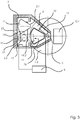
- a second embodiment of the cryolayer system according to the invention is in Fig. 3 shown as a horizontal section through the intermediate storage 2 and the working space 3 above the transport device 18 and through the opened second access 2.1.
- the base of the intermediate storage 2 has the shape of a non-isosceles trapezium, is dimensioned so that only one sample carrier 10 fits into the intermediate storage 2 and covers only a portion of the ceiling of the cryogenic space 1 forming Kryoraumdecke 1.3.
- the temperature and a vertical temperature stratification in the intermediate storage 2 can be regulated by means of the cooling device 17.
- a sample carrier 10 has been transported from the arranged under the intermediate storage 2 Cryo space 1.
- a drawer 11 located in the sample carrier 10, which is located at the level of the second access 2.1 and is delivered to a transfer position 26 in the transport plane 18.3 (not shown).
- the transfer position 26 (symbolized by an arrow) is determined by a relative angular position of the sample carrier 10 transported into the intermediate storage 2 about the axis of rotation 9 and a vertical position, which make it possible to remove or insert a drawer 11 through the transport platform 18.2 or in the sample carrier 10 is possible.
- Another drawer 11 is removed by the transport device 18 from the sample carrier 10, transported by the second access 2.1 in the working space 3 and stored in the working space 3 side of the second access 2.1.
- the contacting means 19 is arranged opposite to the second access 2.1 such that a drawer 11 transported by means of the transport platform 18.2 between the working space 3 and the intermediate storage 2 and / or the samples contained therein can be contacted.
- samples could be taken from the sample vessel 22 and sorted into the drawer 11 stored in the working space 3.
- a further cooling device 17 is arranged in the working space 3. This is connected to the controller 8.
- the actual cooling capacities of the cooling devices 17 in the intermediate storage 2 and the working space 3 are mutually tunable by the controller 8. It is also possible that at least one temperature sensor is present in at least one of the chambers cryogenic space 1, intermediate storage 2 and working space 3, which is in communication with the controller 8.
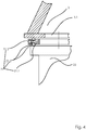
- FIG. 4 An embodiment of a sealing member 21 is according to the Fig. 4 shown as a section.
- a holder 21.1 Around the third access 3.1 encircling a holder 21.1 is arranged on the outwardly facing side of the bottom of the working space 3 of good heat conducting material.
- Two round sealing rubbers 21.2 are inserted into grooves of the holder 21.1 so that a sealing rubber 21.2 facing upward and in contact with the bottom of the working space 3 and the other sealing rubber 21.2 down and is in contact with an upper edge of the locked sample vessel 22.
- a heating element 21.3 is inserted, which is regulated in terms of its heating power by the controller 8 (not shown here).
- the holder 21.1 is cold-insulated against a cryogenic interior of the sample vessel 22.
- a cryolayer system according to the invention will be described below with reference to FIG Fig. 1 and 2 be explained.
- samples are included, of which information such as the nature of the sample and its location in the respective sample carriers 10 and the drawers 11 and their position within the drawer 11 are stored known and retrievable.
- the above-mentioned information for localization of the sample is sent to the controller 8. From this, a control command issued to the drive 7 of the sample carrier receptacle 4.
- the sample carrier receptacle 4 is rotated about the axis of rotation 9 until the sample carrier 10 containing the desired sample is below the first access 1.1 and is delivered thereto.
- the first coupling elements 13.1 of the delivered sample carrier 10 and the second coupling elements 13.2 of the first closure 1.2 are set in such a way that they intermesh with one another without touching each other.
- the intermediate storage 2 has a vertical temperature profile, which is adjusted by means of the cooling device 17 so that none of the drawers 11 of the sample carrier 10 reaches areas with temperatures warmer than the working temperature.
- the intermediate storage 2 and the working space 3 are continuously cooled (stand-by function).
- cryolayer system it is also possible in a further embodiment of the cryolayer system according to the invention that first the intermediate storage 2 to a certain temperature, for. B. - 100 ° C, cooled.
- the working space 3 is opened by opening the second access 2.1, which is controlled with regard to its duration and its degree (eg, half or complete removal of the second closure 2.2), to a specific temperature, e.g. B. between -20 ° and -100 ° C, cooled.
- the opening of the second closure 2.2 can, in support of the regulation of the cooling device 17, be used to regulate the temperature of the working space 3 and to set desired vertical temperature profiles in the intermediate storage 2 and working space 3.
- a vertical position of the transfer position 26 is defined, to which the drawer 11 is delivered with the sample.
- the first access 1.1 is opened while the second access 2.1 is still closed.
- the transport platform 18.2 is moved through the second access 2.1 through in the transport plane 18.3 under the drawer 11 with the sample. Subsequently, the sample carrier 10 is lowered due to a control command of the controller 8 to the chain drive 15 by such an amount that the drawer 11 comes into contact with the transport platform 18.2 and is dug.
- the transport platform 18.2 can be raised by a certain amount.
- the transport platform 18.2 is removed with the drawer 11 from the sample carrier 10 and transported through the second access 2.1 in the working space 3.
- the second access 2.1 can be closed again. It is also possible to move the sample carrier 10 into another transfer position 26 or lower it again into the cryo chamber 1. Also, a transport of another sample carrier 10 in the intermediate storage 2 is possible.
- the drawer 11 transported into the working space 3 is contacted by the contacting means 19 on a storage means of the drawer 11 and the recorded data is compared with the data stored in a database or the controller 8. This makes it possible to check whether the correct drawer 11 has been removed. In addition, the removal of the drawer 11 and possibly the sample can be documented in the database. If also the sample is provided with a storage medium, this is also contacted, whereby the correctness of the position of the sample can be controlled.
- a cryogenic liquid filled with liquid nitrogen sample vessel 22 is delivered and locked at this.
- the heating element 21.3 of the sealing element 21 is turned on, so that the sealing rubbers 21.2 are kept at a temperature warmer than -40 ° C.
- the third access 3.1 is opened by an operator by means of the gloves through the interventions 23 and the sample is removed from the drawer 11 and introduced into the sample vessel 22 through the third access 3.1.
- the third access 3.1 is closed and the sample vessel 22 is released from the locking device 20.
- the drawer 11 is inserted by means of the transport platform 18.2 through the now opened second closure 2.2 again in the sample carrier 10 and the sample carrier 10 is raised, so that the drawer 11 is received again in the sample carrier 10.
- the transport platform 18.2 is moved back into the working space 3.
- the sample carrier 10 is then transported by lowering the first closure 1.2 into the cryo chamber 1 and deposited on the sample carrier receptacle 4. First and second access 1.1, 2.1 are closed again.
- the cryolayer system according to the invention can be used for receiving, storing and dispensing samples, in particular biological samples, for example in the fields of medical, pharmaceutical and chemical research as well as in the clinical field.
Landscapes
- Life Sciences & Earth Sciences (AREA)
- Engineering & Computer Science (AREA)
- Health & Medical Sciences (AREA)
- General Health & Medical Sciences (AREA)
- Chemical & Material Sciences (AREA)
- Pathology (AREA)
- Environmental Sciences (AREA)
- Zoology (AREA)
- Wood Science & Technology (AREA)
- Dentistry (AREA)
- Physics & Mathematics (AREA)
- Combustion & Propulsion (AREA)
- Analytical Chemistry (AREA)
- Public Health (AREA)
- Animal Behavior & Ethology (AREA)
- Surgery (AREA)
- Mechanical Engineering (AREA)
- Thermal Sciences (AREA)
- General Engineering & Computer Science (AREA)
- Robotics (AREA)
- Veterinary Medicine (AREA)
- Biochemistry (AREA)
- General Physics & Mathematics (AREA)
- Immunology (AREA)
- Molecular Biology (AREA)
- Medical Informatics (AREA)
- Heart & Thoracic Surgery (AREA)
- Biomedical Technology (AREA)
- Warehouses Or Storage Devices (AREA)
- Sampling And Sample Adjustment (AREA)
Claims (14)
- Système de stockage cryogénique pour recevoir, stocker et distribuer des échantillons comprenant un espace cryogénique thermiquement isolé dans lequel se trouvent des portes-échantillon pour recevoir les échantillons et un premier accès verrouillable dans une partie supérieure du plafond de l'espace cryogénique par lequel l'espace cryogénique communique avec un stockage intermédiaire thermiquement isolé disposé au-dessus de l'espace cryogénique ; un moyen pour transporter au moins un porte-échantillon entre l'espace cryogénique et le stockage intermédiaire ; avec un espace de travail contigu latéralement au stockage intermédiaire, dans lequel espace de travail sont disposés des moyens pour transporter dans celui-ci, dans au moins une direction horizontale, des éléments d'un porte-échantillon situé dans le stockage intermédiaire, lesquels éléments peuvent être retirés individuellement du porte-échantillon et réinsérés dans celui-ci, et dans lequel est prévue un sas pour transporter des échantillons entre un récipient de transport d'échantillons et l'espace de travail, où- un réceptacle de porte-échantillon (4) destiné à recevoir plusieurs portes-échantillon (10) est présent dans l'espace cryogénique (1) ;- le réceptacle de porte-échantillon (4) est monté de manière mobile et relié à un entraînement commandé (7) de sorte que les différents portes-échantillon (10) peuvent être amenés au premier accès (1.1) de l'espace cryogénique (1) ;- le stockage intermédiaire (2) et l'espace de travail (3) sont isolés thermiquement l'un de l'autre ;- le stockage intermédiaire (2) et l'espace de travail (3) sont reliés entre eux par un deuxième accès (2.1) verrouillable ;- le fond de l'espace de travail (3) est accessible au moins sur une zone par le dessous et par l'extérieur de l'espace cryogénique (1), et dans le fond de l'espace de travail (3) il y a un troisième accès (3.1) verrouillable, comportant un élément d'étanchéité (21) et un dispositif de verrouillage (20) pour verrouiller de manière amovible un récipient d'échantillon (22) de telle sorte que le récipient d'échantillon (22) peut être verrouillé de manière étanche au gaz au niveau du troisième accès (3.1) de l'espace de travail (3) et des échantillons peuvent être transportés entre un récipient d'échantillon verrouillé (22) et l'espace de travail (3).
- Système de stockage cryogénique selon la revendication 1, caractérisé en ce que les éléments des portes-échantillon (10) qui peuvent être retirés du porte-échantillon (10) et réinsérés dans celui-ci sont des tiroirs individuels (11) ayant chacun une surface de base d'un secteur cylindrique.
- Système de stockage cryogénique selon la revendication 2, caractérisé en ce que les tiroirs (11) d'un porte-échantillon (10) situé dans le stockage intermédiaire (2) peuvent être avancés vers une position de transfert (26) en positionnant le porte-échantillon (10), et les moyens pour transporter les tiroirs (11) entre un porte-échantillon (10) situé dans le stockage intermédiaire (2) et l'espace de travail (3) peuvent être avancés vers la position de transfert (26), la position de transfert (26) étant définie de telle sorte qu'un transport de tiroirs (11) à travers le deuxième accès (2.1) soit rendu possible.
- Système de stockage cryogénique selon l'une quelconque des revendications précédentes, caractérisé en ce que le deuxième accès (2.1) présente une extension verticale (a) entre le stockage intermédiaire (2) et l'espace de travail (3), sur laquelle des tiroirs (11) peuvent être transportés horizontalement entre le stockage intermédiaire (2) et l'espace de travail (3) et l'extension verticale (a) du deuxième accès (2.1) se termine à une distance des zones de plafond respectives du stockage intermédiaire (2) et de l'espace de travail (3).
- Système de stockage cryogénique selon la revendication 4, caractérisé en ce que le réceptacle de porte-échantillon (4) est disposé autour d'un arbre (5) s'étendant coaxialement à un axe de rotation (9) et y est relié, l'arbre (5) étant monté à son extrémité située dans l'espace cryogénique (1) dans un palier (6), de manière à pouvoir être tourné autour de l'axe de rotation (9), et le récepteur de porte-échantillon (4) étant monté sur des rouleaux fixes (4.2) avec sa face inférieure, qui dépassent du fond de l'espace cryogénique (1) en direction de la face inférieure du réceptacle de porte-échantillon (4).
- Système de stockage cryogénique selon l'une quelconque des revendications précédentes, caractérisé en ce que le dimensionnement du stockage intermédiaire (2) permet la réception simultanée d'un seul porte échantillon (10) à la fois.
- Système de stockage cryogénique selon la revendication 6, caractérisé en ce qu'une première fermeture (1.2) est présente au niveau du premier accès (1.1), qui présente des premiers éléments d'accouplement (13.1) sur son côté dirigé vers l'espace cryogénique (1), et chaque porte-échantillon (10) présente des deuxièmes éléments d'accouplement (13.2), les premiers éléments d'accouplement (13.1) et les deuxièmes éléments d'accouplement (13.2) formant un accouplement (13) pour relier de manière amovible la première fermeture (1.2) et un porte-échantillon (10) qui est amené au premier accès (1.1) et au moyen duquel accouplement un porte-échantillon (10) couplé à la première fermeture (1.2) peut être transporté entre l'espace cryogénique (1) et le stockage intermédiaire (2).
- Système de stockage cryogénique selon la revendication 7, caractérisé en ce que la première fermeture (1.2) est reliée par une chaîne (15) à un entraînement à chaîne (16).
- Système de stockage cryogénique selon l'une quelconque des revendications précédentes, caractérisé en ce que le moyen pour transporter les tiroirs (11) entre le porte-échantillon (10) situé dans le stockage intermédiaire (2) et l'espace de travail (3) est un dispositif de transport (18) qui est entraîné par un moyen de traction et par lequel un tiroir (11) transporté dans l'espace de travail (3) peut être amené à une position d'accès ayant des coordonnées définies dans l'espace de travail (3).
- Système de stockage cryogénique selon la revendication 9, caractérisé en ce que des moyens de stockage pour stocker et fournir des données sont présents sur chaque tiroir (11).
- Système de stockage cryogénique selon la revendication 10, caractérisé en ce que des moyens de contact (19) pour entrer en contact avec les moyens de stockage d'un tiroir (11) transporté dans l'espace de travail (3) sont présents dans l'espace de travail (3), ce contact permettant d'échanger des données entre les moyens de contact (19) et les moyens de stockage.
- Système de stockage cryogénique selon la revendication 1, caractérisé en ce que l'élément d'étanchéité (21) est chauffable.
- Système de stockage cryogénique selon l'une quelconque des revendications précédentes, caractérisé en ce qu'au moins une ouverture d'intervention (23) est présente dans l'espace de travail (3) pour manipuler des échantillons par le troisième accès (3.1) et dans l'espace de travail (3).
- Système de stockage cryogénique selon l'une quelconque des revendications précédentes, caractérisé en ce que dans l'espace de travail (3) se trouve un dispositif de manipulation commandé pour manipuler des échantillons par le troisième accès (3.1) et dans l'espace de travail (3).
Applications Claiming Priority (1)
| Application Number | Priority Date | Filing Date | Title |
|---|---|---|---|
| DE102011012887A DE102011012887B4 (de) | 2011-02-28 | 2011-02-28 | Kryospeichereinrichtung |
Publications (3)
| Publication Number | Publication Date |
|---|---|
| EP2492663A2 EP2492663A2 (fr) | 2012-08-29 |
| EP2492663A3 EP2492663A3 (fr) | 2015-07-08 |
| EP2492663B1 true EP2492663B1 (fr) | 2019-12-04 |
Family
ID=45656009
Family Applications (1)
| Application Number | Title | Priority Date | Filing Date |
|---|---|---|---|
| EP12155883.7A Active EP2492663B1 (fr) | 2011-02-28 | 2012-02-17 | Système de stockage cryogénique |
Country Status (2)
| Country | Link |
|---|---|
| EP (1) | EP2492663B1 (fr) |
| DE (1) | DE102011012887B4 (fr) |
Cited By (11)
| Publication number | Priority date | Publication date | Assignee | Title |
|---|---|---|---|---|
| CN109640648A (zh) * | 2016-05-17 | 2019-04-16 | 易锐莱科有限公司 | 在非常低的温度下操纵和储存生物样本的装置 |
| US11607691B2 (en) | 2019-10-29 | 2023-03-21 | TMRW Life Sciences, Inc. | Apparatus to facilitate transfer of biological specimens stored at cryogenic conditions |
| US11632949B2 (en) | 2020-09-24 | 2023-04-25 | TMRW Life Sciences, Inc. | Cryogenic storage system with sensors to measure one or more parameters therewithin |
| USD1002868S1 (en) | 2020-12-09 | 2023-10-24 | TMRW Life Sciences, Inc. | Cryogenic vial carrier |
| US11817187B2 (en) | 2020-05-18 | 2023-11-14 | TMRW Life Sciences, Inc. | Handling and tracking of biological specimens for cryogenic storage |
| US12017227B2 (en) | 2020-12-10 | 2024-06-25 | TMRW Life Sciences, Inc. | Specimen holder with wireless transponder for attachment to specimen collection body |
| US12099890B2 (en) | 2020-10-02 | 2024-09-24 | TMRW Life Sciences, Inc. | Interrogation device and/or system having alignment feature(s) for wireless transponder tagged specimen containers and/or carriers |
| EP4388240A4 (fr) * | 2021-08-22 | 2024-12-11 | Crinsurance S.A.S. | Système automatisé de vitrification, stockage et décongélation d'échantillons biologiques |
| US12259399B2 (en) | 2021-01-13 | 2025-03-25 | TMRW Life Sciences, Inc. | Systems, apparatus and methods to pick and/or place specimen containers |
| US12285009B2 (en) | 2020-09-24 | 2025-04-29 | TMRW Life Sciences, Inc. | Workstation and apparatus to facilitate transfer of biological specimens stored at cryogenic conditions |
| US12527318B2 (en) | 2021-10-08 | 2026-01-20 | TMRW Life Sciences, Inc. | Systems, apparatus and methods to pick and/or place specimen containers |
Families Citing this family (38)
| Publication number | Priority date | Publication date | Assignee | Title |
|---|---|---|---|---|
| DE102012024105A1 (de) | 2012-12-10 | 2014-06-12 | Fraunhofer-Gesellschaft zur Förderung der angewandten Forschung e.V. | Kryo-Lagereinrichtung und Verfahren zu deren Betrieb |
| JP2017508984A (ja) * | 2014-01-20 | 2017-03-30 | ブルックス オートメーション インコーポレイテッド | 持ち運び可能な低温ワークステーション |
| DE102014018308A1 (de) | 2014-12-10 | 2016-06-16 | Fraunhofer-Gesellschaft zur Förderung der angewandten Forschung e.V. | Temperierkörper für eine Multiwell-Platte und Verfahren und Vorrichtung zum Einfrieren und/oder Auftauen von biologischen Proben |
| WO2016160984A1 (fr) * | 2015-03-30 | 2016-10-06 | Brooks Automation, Inc. | Système de stockage cryogénique automatisé |
| US10421607B2 (en) * | 2015-03-30 | 2019-09-24 | Brooks Automation, Inc. | Cryogenic freezer |
| CN105379706B (zh) * | 2015-10-22 | 2018-01-16 | 上海原能细胞医学技术有限公司 | 冷冻细胞的自动存取控制装置 |
| CN105857932B (zh) * | 2016-04-28 | 2018-02-13 | 上海原能健康管理有限公司 | 冻存管存取装置 |
| CN105857941B (zh) * | 2016-04-28 | 2018-06-29 | 上海原能健康管理有限公司 | 冻存管存取装置 |
| CN105857937B (zh) * | 2016-04-28 | 2018-05-08 | 上海原能健康管理有限公司 | 冻存管存取装置以及液氮罐存取系统 |
| EP3481180B1 (fr) * | 2016-07-08 | 2023-06-07 | Stephan Hammelbacher | Carrousel isolateur |
| CN107333748A (zh) * | 2016-11-15 | 2017-11-10 | 成都叮当自动化设备有限公司 | 一种冷冻细胞的自动存取系统 |
| DE102016124721B4 (de) * | 2016-12-16 | 2019-08-29 | KD Maennel GmbH | Modulares Kryolagerungssystem zur Lagerung von Proben, insbesondere zur Tieftemperatur-Lagerung von biologischen Proben |
| DE102016124720B4 (de) | 2016-12-16 | 2019-08-14 | KD Maennel GmbH | Kryolagerungsvorrichtung zur Lagerung von Proben, insbesondere zur Tieftemperatur-Lagerung von biologischen Proben |
| DE102016124723B4 (de) | 2016-12-16 | 2019-03-28 | KD Maennel GmbH | Lagerungsvorrichtung zur Lagerung von Proben, insbesondere zur Tieftemperatur-Lagerung von biologischen Proben |
| DE102016124722B4 (de) | 2016-12-16 | 2018-10-04 | KD Maennel GmbH | Handhabungseinrichtung, insbesondere für eine Lagerungsvorrichtung |
| CN106628786B (zh) * | 2017-02-20 | 2022-04-29 | 上海原能细胞生物低温设备有限公司 | 低温样本存取装置 |
| CN107062731A (zh) * | 2017-02-20 | 2017-08-18 | 上海原能细胞医学技术有限公司 | 自动化存储装置及其运行方法 |
| CN107697530B (zh) * | 2017-09-21 | 2023-10-10 | 基点生物科技(成都)有限公司 | 基因样本传送仓 |
| CN107980764B (zh) * | 2017-11-28 | 2022-11-22 | 上海原能细胞生物低温设备有限公司 | 一种低温中转箱 |
| CN109928071A (zh) * | 2017-12-15 | 2019-06-25 | 国玺干细胞应用技术股份有限公司 | 智能科技生物产品低温储存设备 |
| CN109928072A (zh) * | 2017-12-15 | 2019-06-25 | 国玺干细胞应用技术股份有限公司 | 智能科技生物产品低温储存设备 |
| EP3833916B1 (fr) | 2018-08-10 | 2026-03-18 | Celltrio, Inc. | Système de stockage cryogénique |
| CN109275657B (zh) * | 2018-09-17 | 2023-07-04 | 上海原能细胞生物低温设备有限公司 | 一种螺旋升降式低温存储装置 |
| CN109368107B (zh) * | 2018-11-09 | 2024-10-11 | 上海原能细胞生物低温设备有限公司 | 一种生物样本储存库及其储存方法 |
| CN110589332B (zh) | 2019-10-08 | 2020-11-06 | 苏州贝康医疗器械有限公司 | 自动化生物样本库 |
| CN110667986A (zh) * | 2019-10-08 | 2020-01-10 | 苏州贝康医疗器械有限公司 | 自动化液氮罐系统 |
| FR3101864B1 (fr) | 2019-10-15 | 2021-10-08 | Irelec | Installation de manipulation et de stockage d’échantillons biologiques à très basses températures, comprenant au moins un robot cartésien et un robot à au moins cinq axes. |
| CN111377184B (zh) * | 2020-04-27 | 2024-06-21 | 上海原能细胞生物低温设备有限公司 | 一种样本转运操作舱 |
| CN112046988A (zh) * | 2020-09-10 | 2020-12-08 | 成都纺织高等专科学校 | 一种生物样本冷藏存储系统 |
| CN112208942B (zh) * | 2020-10-19 | 2024-06-14 | 上海原能细胞生物低温设备有限公司 | 存取设备 |
| CN114279147A (zh) * | 2021-01-15 | 2022-04-05 | 青岛海特生物医疗有限公司 | 疫苗冷藏取放一体库 |
| CN214853921U (zh) * | 2021-05-11 | 2021-11-26 | 上海原能细胞生物低温设备有限公司 | 一种样本降温存储机构 |
| CN115682573B (zh) * | 2021-07-29 | 2025-09-19 | 苏州碳卡智能科技有限公司 | 自动化深低温冷链储存生物样本装置及使用方法 |
| CN113879822A (zh) * | 2021-09-18 | 2022-01-04 | 青岛普天智能制造股份有限公司 | 一种冻存盒的存取装置及其方法 |
| CN217520113U (zh) * | 2022-04-15 | 2022-09-30 | 上海原能细胞生物低温设备有限公司 | 一种全冷链式铲盘装置 |
| CN217837014U (zh) * | 2022-06-27 | 2022-11-18 | 上海葆能生物科技有限公司 | 一种用于生物样本的低温存储系统 |
| CN115590019B (zh) * | 2022-11-25 | 2023-03-17 | 齐齐哈尔医学院 | 一种普外科术后取材组织保鲜存放设备 |
| CN118790630A (zh) * | 2024-07-29 | 2024-10-18 | 上海原能细胞生物低温设备有限公司 | 一种超低温样本存储设备 |
Family Cites Families (5)
| Publication number | Priority date | Publication date | Assignee | Title |
|---|---|---|---|---|
| US5233844A (en) * | 1991-08-15 | 1993-08-10 | Cryo-Cell International, Inc. | Storage apparatus, particularly with automatic insertion and retrieval |
| DE10332799B4 (de) * | 2003-07-18 | 2007-03-01 | Fraunhofer-Gesellschaft zur Förderung der angewandten Forschung e.V. | Vorrichtung und Verfahren zur Handhabung einer Probe |
| DE202007002712U1 (de) * | 2007-02-21 | 2007-05-10 | Klarer & Zwicky Ag | Isoliertüre mit Brandschutzeigenschaften für Kühlräume oder Tiefkühlräume |
| DE102008057981B4 (de) * | 2008-11-19 | 2010-09-02 | Fraunhofer-Gesellschaft zur Förderung der angewandten Forschung e.V. | Kryospeichereinrichtung |
| WO2010065772A1 (fr) * | 2008-12-03 | 2010-06-10 | Translogic Corporation | Système de stockage et de récupération automatique de température double |
-
2011
- 2011-02-28 DE DE102011012887A patent/DE102011012887B4/de not_active Expired - Fee Related
-
2012
- 2012-02-17 EP EP12155883.7A patent/EP2492663B1/fr active Active
Non-Patent Citations (1)
| Title |
|---|
| None * |
Cited By (15)
| Publication number | Priority date | Publication date | Assignee | Title |
|---|---|---|---|---|
| CN109640648B (zh) * | 2016-05-17 | 2022-07-08 | 易锐莱科有限公司 | 在非常低的温度下操纵和储存生物样本的装置 |
| CN109640648A (zh) * | 2016-05-17 | 2019-04-16 | 易锐莱科有限公司 | 在非常低的温度下操纵和储存生物样本的装置 |
| US11607691B2 (en) | 2019-10-29 | 2023-03-21 | TMRW Life Sciences, Inc. | Apparatus to facilitate transfer of biological specimens stored at cryogenic conditions |
| US12290816B2 (en) | 2019-10-29 | 2025-05-06 | TMRW Life Sciences, Inc. | Apparatus to facilitate transfer of biological specimens stored at cryogenic conditions |
| US11817187B2 (en) | 2020-05-18 | 2023-11-14 | TMRW Life Sciences, Inc. | Handling and tracking of biological specimens for cryogenic storage |
| US12354716B2 (en) | 2020-05-18 | 2025-07-08 | TMRW Life Sciences, Inc. | Handling and tracking of biological specimens for cryogenic storage |
| US12285009B2 (en) | 2020-09-24 | 2025-04-29 | TMRW Life Sciences, Inc. | Workstation and apparatus to facilitate transfer of biological specimens stored at cryogenic conditions |
| US11632949B2 (en) | 2020-09-24 | 2023-04-25 | TMRW Life Sciences, Inc. | Cryogenic storage system with sensors to measure one or more parameters therewithin |
| US12099890B2 (en) | 2020-10-02 | 2024-09-24 | TMRW Life Sciences, Inc. | Interrogation device and/or system having alignment feature(s) for wireless transponder tagged specimen containers and/or carriers |
| USD1002868S1 (en) | 2020-12-09 | 2023-10-24 | TMRW Life Sciences, Inc. | Cryogenic vial carrier |
| US12017227B2 (en) | 2020-12-10 | 2024-06-25 | TMRW Life Sciences, Inc. | Specimen holder with wireless transponder for attachment to specimen collection body |
| US12383905B2 (en) | 2020-12-10 | 2025-08-12 | TMRW Life Sciences, Inc. | Specimen holder with wireless transponder for attachment to specimen collection body |
| US12259399B2 (en) | 2021-01-13 | 2025-03-25 | TMRW Life Sciences, Inc. | Systems, apparatus and methods to pick and/or place specimen containers |
| EP4388240A4 (fr) * | 2021-08-22 | 2024-12-11 | Crinsurance S.A.S. | Système automatisé de vitrification, stockage et décongélation d'échantillons biologiques |
| US12527318B2 (en) | 2021-10-08 | 2026-01-20 | TMRW Life Sciences, Inc. | Systems, apparatus and methods to pick and/or place specimen containers |
Also Published As
| Publication number | Publication date |
|---|---|
| EP2492663A2 (fr) | 2012-08-29 |
| DE102011012887B4 (de) | 2012-09-20 |
| DE102011012887A1 (de) | 2012-08-30 |
| EP2492663A3 (fr) | 2015-07-08 |
Similar Documents
| Publication | Publication Date | Title |
|---|---|---|
| EP2492663B1 (fr) | Système de stockage cryogénique | |
| DE60125380T2 (de) | Automatisiertes lagerungs- und entnahmegerät für gefrierfächer und entsprechendes verfahren | |
| DE69230405T2 (de) | Lagervorrichtung, insbesondere mit automatischem ein- sowie auslagern | |
| DE69637226T2 (de) | Tiefsttemperaturlagerung von wärme-unbeständigen waren | |
| EP1920044B1 (fr) | Systeme de plusieurs incubateurs | |
| DE69835359T2 (de) | Verfahren und vorrichtung zur tiefsttemperaturlagerung von wärme-unbeständigen waren | |
| EP1939561A2 (fr) | Systeme de stockage compact et son utilisation | |
| EP2644537B1 (fr) | Archivage d'échantillons | |
| EP3581864B1 (fr) | Installation de stockage d'objets de laboratoire à basses températures | |
| EP1797379B1 (fr) | Dispositif cryogenique et procede permettant de faire fonctionner ledit dispositif | |
| WO2016016001A1 (fr) | Poste de chargement permettant le transfert à basses températures d'échantillons congelés | |
| DE102012024105A1 (de) | Kryo-Lagereinrichtung und Verfahren zu deren Betrieb | |
| WO2005010499A2 (fr) | Dispositif et procede de manipulation d'un echantillon | |
| DE102010012790A1 (de) | Inkubatoreinrichtung und Verfahren zu deren Betrieb | |
| DE102004053170B4 (de) | Lagerungssystem | |
| DE10304012B4 (de) | Klimaschrank | |
| EP2358196A1 (fr) | Dispositif de cryo-accumulation | |
| DE102016124720B4 (de) | Kryolagerungsvorrichtung zur Lagerung von Proben, insbesondere zur Tieftemperatur-Lagerung von biologischen Proben | |
| DE102007044016A1 (de) | Probenwechseleinrichtung mit auf mäanderförmiger Bahn geführten Probenaufnahmen, insbesondere für ein NMR-Spektrometer | |
| EP4421420A1 (fr) | Système de régulation de température et son procédé de commande | |
| DE102016124722B4 (de) | Handhabungseinrichtung, insbesondere für eine Lagerungsvorrichtung | |
| DE69908271T2 (de) | Vorrichtung zum automatischen speichern von biologischen oder chemischen proben | |
| DE102016124721B4 (de) | Modulares Kryolagerungssystem zur Lagerung von Proben, insbesondere zur Tieftemperatur-Lagerung von biologischen Proben | |
| EP3161122A1 (fr) | Cadre de montage pour une étuve bactériologique | |
| EP2385101B1 (fr) | Incubateur dotée de plusieurs stations d'entrée et muni de moyen de transport |
Legal Events
| Date | Code | Title | Description |
|---|---|---|---|
| PUAI | Public reference made under article 153(3) epc to a published international application that has entered the european phase |
Free format text: ORIGINAL CODE: 0009012 |
|
| AK | Designated contracting states |
Kind code of ref document: A2 Designated state(s): AL AT BE BG CH CY CZ DE DK EE ES FI FR GB GR HR HU IE IS IT LI LT LU LV MC MK MT NL NO PL PT RO RS SE SI SK SM TR |
|
| AX | Request for extension of the european patent |
Extension state: BA ME |
|
| PUAL | Search report despatched |
Free format text: ORIGINAL CODE: 0009013 |
|
| AK | Designated contracting states |
Kind code of ref document: A3 Designated state(s): AL AT BE BG CH CY CZ DE DK EE ES FI FR GB GR HR HU IE IS IT LI LT LU LV MC MK MT NL NO PL PT RO RS SE SI SK SM TR |
|
| AX | Request for extension of the european patent |
Extension state: BA ME |
|
| RIC1 | Information provided on ipc code assigned before grant |
Ipc: G01N 1/42 20060101AFI20150602BHEP Ipc: B65G 1/00 20060101ALI20150602BHEP Ipc: A01N 1/02 20060101ALI20150602BHEP Ipc: A61B 10/00 20060101ALI20150602BHEP Ipc: G01N 35/00 20060101ALI20150602BHEP Ipc: F25D 19/00 20060101ALI20150602BHEP |
|
| 17P | Request for examination filed |
Effective date: 20160104 |
|
| RBV | Designated contracting states (corrected) |
Designated state(s): AL AT BE BG CH CY CZ DE DK EE ES FI FR GB GR HR HU IE IS IT LI LT LU LV MC MK MT NL NO PL PT RO RS SE SI SK SM TR |
|
| GRAP | Despatch of communication of intention to grant a patent |
Free format text: ORIGINAL CODE: EPIDOSNIGR1 |
|
| STAA | Information on the status of an ep patent application or granted ep patent |
Free format text: STATUS: GRANT OF PATENT IS INTENDED |
|
| RIC1 | Information provided on ipc code assigned before grant |
Ipc: A01N 1/02 20060101ALI20190617BHEP Ipc: A61B 10/00 20060101ALI20190617BHEP Ipc: B65G 1/00 20060101ALI20190617BHEP Ipc: F25D 13/06 20060101ALI20190617BHEP Ipc: F25D 19/00 20060101ALI20190617BHEP Ipc: G01N 35/00 20060101ALI20190617BHEP Ipc: G01N 1/42 20060101AFI20190617BHEP |
|
| INTG | Intention to grant announced |
Effective date: 20190710 |
|
| GRAS | Grant fee paid |
Free format text: ORIGINAL CODE: EPIDOSNIGR3 |
|
| GRAA | (expected) grant |
Free format text: ORIGINAL CODE: 0009210 |
|
| STAA | Information on the status of an ep patent application or granted ep patent |
Free format text: STATUS: THE PATENT HAS BEEN GRANTED |
|
| AK | Designated contracting states |
Kind code of ref document: B1 Designated state(s): AL AT BE BG CH CY CZ DE DK EE ES FI FR GB GR HR HU IE IS IT LI LT LU LV MC MK MT NL NO PL PT RO RS SE SI SK SM TR |
|
| REG | Reference to a national code |
Ref country code: GB Ref legal event code: FG4D Free format text: NOT ENGLISH |
|
| REG | Reference to a national code |
Ref country code: CH Ref legal event code: EP |
|
| REG | Reference to a national code |
Ref country code: AT Ref legal event code: REF Ref document number: 1209986 Country of ref document: AT Kind code of ref document: T Effective date: 20191215 |
|
| REG | Reference to a national code |
Ref country code: DE Ref legal event code: R096 Ref document number: 502012015578 Country of ref document: DE |
|
| REG | Reference to a national code |
Ref country code: IE Ref legal event code: FG4D Free format text: LANGUAGE OF EP DOCUMENT: GERMAN |
|
| REG | Reference to a national code |
Ref country code: NL Ref legal event code: MP Effective date: 20191204 |
|
| REG | Reference to a national code |
Ref country code: LT Ref legal event code: MG4D |
|
| PG25 | Lapsed in a contracting state [announced via postgrant information from national office to epo] |
Ref country code: LV Free format text: LAPSE BECAUSE OF FAILURE TO SUBMIT A TRANSLATION OF THE DESCRIPTION OR TO PAY THE FEE WITHIN THE PRESCRIBED TIME-LIMIT Effective date: 20191204 Ref country code: SE Free format text: LAPSE BECAUSE OF FAILURE TO SUBMIT A TRANSLATION OF THE DESCRIPTION OR TO PAY THE FEE WITHIN THE PRESCRIBED TIME-LIMIT Effective date: 20191204 Ref country code: BG Free format text: LAPSE BECAUSE OF FAILURE TO SUBMIT A TRANSLATION OF THE DESCRIPTION OR TO PAY THE FEE WITHIN THE PRESCRIBED TIME-LIMIT Effective date: 20200304 Ref country code: LT Free format text: LAPSE BECAUSE OF FAILURE TO SUBMIT A TRANSLATION OF THE DESCRIPTION OR TO PAY THE FEE WITHIN THE PRESCRIBED TIME-LIMIT Effective date: 20191204 Ref country code: FI Free format text: LAPSE BECAUSE OF FAILURE TO SUBMIT A TRANSLATION OF THE DESCRIPTION OR TO PAY THE FEE WITHIN THE PRESCRIBED TIME-LIMIT Effective date: 20191204 Ref country code: NO Free format text: LAPSE BECAUSE OF FAILURE TO SUBMIT A TRANSLATION OF THE DESCRIPTION OR TO PAY THE FEE WITHIN THE PRESCRIBED TIME-LIMIT Effective date: 20200304 Ref country code: GR Free format text: LAPSE BECAUSE OF FAILURE TO SUBMIT A TRANSLATION OF THE DESCRIPTION OR TO PAY THE FEE WITHIN THE PRESCRIBED TIME-LIMIT Effective date: 20200305 Ref country code: ES Free format text: LAPSE BECAUSE OF FAILURE TO SUBMIT A TRANSLATION OF THE DESCRIPTION OR TO PAY THE FEE WITHIN THE PRESCRIBED TIME-LIMIT Effective date: 20191204 |
|
| PG25 | Lapsed in a contracting state [announced via postgrant information from national office to epo] |
Ref country code: HR Free format text: LAPSE BECAUSE OF FAILURE TO SUBMIT A TRANSLATION OF THE DESCRIPTION OR TO PAY THE FEE WITHIN THE PRESCRIBED TIME-LIMIT Effective date: 20191204 Ref country code: RS Free format text: LAPSE BECAUSE OF FAILURE TO SUBMIT A TRANSLATION OF THE DESCRIPTION OR TO PAY THE FEE WITHIN THE PRESCRIBED TIME-LIMIT Effective date: 20191204 |
|
| PG25 | Lapsed in a contracting state [announced via postgrant information from national office to epo] |
Ref country code: AL Free format text: LAPSE BECAUSE OF FAILURE TO SUBMIT A TRANSLATION OF THE DESCRIPTION OR TO PAY THE FEE WITHIN THE PRESCRIBED TIME-LIMIT Effective date: 20191204 |
|
| PG25 | Lapsed in a contracting state [announced via postgrant information from national office to epo] |
Ref country code: PT Free format text: LAPSE BECAUSE OF FAILURE TO SUBMIT A TRANSLATION OF THE DESCRIPTION OR TO PAY THE FEE WITHIN THE PRESCRIBED TIME-LIMIT Effective date: 20200429 Ref country code: CZ Free format text: LAPSE BECAUSE OF FAILURE TO SUBMIT A TRANSLATION OF THE DESCRIPTION OR TO PAY THE FEE WITHIN THE PRESCRIBED TIME-LIMIT Effective date: 20191204 Ref country code: NL Free format text: LAPSE BECAUSE OF FAILURE TO SUBMIT A TRANSLATION OF THE DESCRIPTION OR TO PAY THE FEE WITHIN THE PRESCRIBED TIME-LIMIT Effective date: 20191204 Ref country code: RO Free format text: LAPSE BECAUSE OF FAILURE TO SUBMIT A TRANSLATION OF THE DESCRIPTION OR TO PAY THE FEE WITHIN THE PRESCRIBED TIME-LIMIT Effective date: 20191204 Ref country code: EE Free format text: LAPSE BECAUSE OF FAILURE TO SUBMIT A TRANSLATION OF THE DESCRIPTION OR TO PAY THE FEE WITHIN THE PRESCRIBED TIME-LIMIT Effective date: 20191204 |
|
| PG25 | Lapsed in a contracting state [announced via postgrant information from national office to epo] |
Ref country code: IS Free format text: LAPSE BECAUSE OF FAILURE TO SUBMIT A TRANSLATION OF THE DESCRIPTION OR TO PAY THE FEE WITHIN THE PRESCRIBED TIME-LIMIT Effective date: 20200404 Ref country code: SK Free format text: LAPSE BECAUSE OF FAILURE TO SUBMIT A TRANSLATION OF THE DESCRIPTION OR TO PAY THE FEE WITHIN THE PRESCRIBED TIME-LIMIT Effective date: 20191204 Ref country code: SM Free format text: LAPSE BECAUSE OF FAILURE TO SUBMIT A TRANSLATION OF THE DESCRIPTION OR TO PAY THE FEE WITHIN THE PRESCRIBED TIME-LIMIT Effective date: 20191204 |
|
| REG | Reference to a national code |
Ref country code: DE Ref legal event code: R097 Ref document number: 502012015578 Country of ref document: DE |
|
| PLBE | No opposition filed within time limit |
Free format text: ORIGINAL CODE: 0009261 |
|
| STAA | Information on the status of an ep patent application or granted ep patent |
Free format text: STATUS: NO OPPOSITION FILED WITHIN TIME LIMIT |
|
| REG | Reference to a national code |
Ref country code: BE Ref legal event code: MM Effective date: 20200229 |
|
| PG25 | Lapsed in a contracting state [announced via postgrant information from national office to epo] |
Ref country code: MC Free format text: LAPSE BECAUSE OF FAILURE TO SUBMIT A TRANSLATION OF THE DESCRIPTION OR TO PAY THE FEE WITHIN THE PRESCRIBED TIME-LIMIT Effective date: 20191204 Ref country code: LU Free format text: LAPSE BECAUSE OF NON-PAYMENT OF DUE FEES Effective date: 20200217 Ref country code: DK Free format text: LAPSE BECAUSE OF FAILURE TO SUBMIT A TRANSLATION OF THE DESCRIPTION OR TO PAY THE FEE WITHIN THE PRESCRIBED TIME-LIMIT Effective date: 20191204 |
|
| 26N | No opposition filed |
Effective date: 20200907 |
|
| PG25 | Lapsed in a contracting state [announced via postgrant information from national office to epo] |
Ref country code: PL Free format text: LAPSE BECAUSE OF FAILURE TO SUBMIT A TRANSLATION OF THE DESCRIPTION OR TO PAY THE FEE WITHIN THE PRESCRIBED TIME-LIMIT Effective date: 20191204 Ref country code: SI Free format text: LAPSE BECAUSE OF FAILURE TO SUBMIT A TRANSLATION OF THE DESCRIPTION OR TO PAY THE FEE WITHIN THE PRESCRIBED TIME-LIMIT Effective date: 20191204 |
|
| PG25 | Lapsed in a contracting state [announced via postgrant information from national office to epo] |
Ref country code: IT Free format text: LAPSE BECAUSE OF FAILURE TO SUBMIT A TRANSLATION OF THE DESCRIPTION OR TO PAY THE FEE WITHIN THE PRESCRIBED TIME-LIMIT Effective date: 20191204 Ref country code: IE Free format text: LAPSE BECAUSE OF NON-PAYMENT OF DUE FEES Effective date: 20200217 |
|
| PG25 | Lapsed in a contracting state [announced via postgrant information from national office to epo] |
Ref country code: BE Free format text: LAPSE BECAUSE OF NON-PAYMENT OF DUE FEES Effective date: 20200229 |
|
| REG | Reference to a national code |
Ref country code: AT Ref legal event code: MM01 Ref document number: 1209986 Country of ref document: AT Kind code of ref document: T Effective date: 20200217 |
|
| PG25 | Lapsed in a contracting state [announced via postgrant information from national office to epo] |
Ref country code: AT Free format text: LAPSE BECAUSE OF NON-PAYMENT OF DUE FEES Effective date: 20200217 |
|
| PG25 | Lapsed in a contracting state [announced via postgrant information from national office to epo] |
Ref country code: TR Free format text: LAPSE BECAUSE OF FAILURE TO SUBMIT A TRANSLATION OF THE DESCRIPTION OR TO PAY THE FEE WITHIN THE PRESCRIBED TIME-LIMIT Effective date: 20191204 Ref country code: MT Free format text: LAPSE BECAUSE OF FAILURE TO SUBMIT A TRANSLATION OF THE DESCRIPTION OR TO PAY THE FEE WITHIN THE PRESCRIBED TIME-LIMIT Effective date: 20191204 Ref country code: CY Free format text: LAPSE BECAUSE OF FAILURE TO SUBMIT A TRANSLATION OF THE DESCRIPTION OR TO PAY THE FEE WITHIN THE PRESCRIBED TIME-LIMIT Effective date: 20191204 |
|
| PG25 | Lapsed in a contracting state [announced via postgrant information from national office to epo] |
Ref country code: MK Free format text: LAPSE BECAUSE OF FAILURE TO SUBMIT A TRANSLATION OF THE DESCRIPTION OR TO PAY THE FEE WITHIN THE PRESCRIBED TIME-LIMIT Effective date: 20191204 |
|
| P01 | Opt-out of the competence of the unified patent court (upc) registered |
Effective date: 20230606 |
|
| REG | Reference to a national code |
Ref country code: DE Ref legal event code: R082 Ref document number: 502012015578 Country of ref document: DE Representative=s name: GLEIM PETRI PATENT- UND RECHTSANWALTSPARTNERSC, DE |
|
| PGFP | Annual fee paid to national office [announced via postgrant information from national office to epo] |
Ref country code: GB Payment date: 20240219 Year of fee payment: 13 Ref country code: CH Payment date: 20240301 Year of fee payment: 13 |
|
| PGFP | Annual fee paid to national office [announced via postgrant information from national office to epo] |
Ref country code: FR Payment date: 20240221 Year of fee payment: 13 |
|
| REG | Reference to a national code |
Ref country code: CH Ref legal event code: PL |
|
| PG25 | Lapsed in a contracting state [announced via postgrant information from national office to epo] |
Ref country code: CH Free format text: LAPSE BECAUSE OF NON-PAYMENT OF DUE FEES Effective date: 20250228 |
|
| GBPC | Gb: european patent ceased through non-payment of renewal fee |
Effective date: 20250217 |
|
| PG25 | Lapsed in a contracting state [announced via postgrant information from national office to epo] |
Ref country code: GB Free format text: LAPSE BECAUSE OF NON-PAYMENT OF DUE FEES Effective date: 20250217 |
|
| PG25 | Lapsed in a contracting state [announced via postgrant information from national office to epo] |
Ref country code: FR Free format text: LAPSE BECAUSE OF NON-PAYMENT OF DUE FEES Effective date: 20250228 |
|
| PGFP | Annual fee paid to national office [announced via postgrant information from national office to epo] |
Ref country code: DE Payment date: 20260218 Year of fee payment: 15 |