EP2492665A1 - Biosensor mit magnetischen mikropartikeln - Google Patents
Biosensor mit magnetischen mikropartikeln Download PDFInfo
- Publication number
- EP2492665A1 EP2492665A1 EP10824893A EP10824893A EP2492665A1 EP 2492665 A1 EP2492665 A1 EP 2492665A1 EP 10824893 A EP10824893 A EP 10824893A EP 10824893 A EP10824893 A EP 10824893A EP 2492665 A1 EP2492665 A1 EP 2492665A1
- Authority
- EP
- European Patent Office
- Prior art keywords
- magnetic field
- light
- dispersion liquid
- magnetic
- biosensor
- Prior art date
- Legal status (The legal status is an assumption and is not a legal conclusion. Google has not performed a legal analysis and makes no representation as to the accuracy of the status listed.)
- Withdrawn
Links
Images

Classifications
-
- G—PHYSICS
- G01—MEASURING; TESTING
- G01N—INVESTIGATING OR ANALYSING MATERIALS BY DETERMINING THEIR CHEMICAL OR PHYSICAL PROPERTIES
- G01N21/00—Investigating or analysing materials by the use of optical means, i.e. using sub-millimetre waves, infrared, visible or ultraviolet light
- G01N21/17—Systems in which incident light is modified in accordance with the properties of the material investigated
- G01N21/1717—Systems in which incident light is modified in accordance with the properties of the material investigated with a modulation of one or more physical properties of the sample during the optical investigation, e.g. electro-reflectance
-
- G—PHYSICS
- G01—MEASURING; TESTING
- G01N—INVESTIGATING OR ANALYSING MATERIALS BY DETERMINING THEIR CHEMICAL OR PHYSICAL PROPERTIES
- G01N33/00—Investigating or analysing materials by specific methods not covered by groups G01N1/00 - G01N31/00
- G01N33/48—Biological material, e.g. blood, urine; Haemocytometers
- G01N33/50—Chemical analysis of biological material, e.g. blood, urine; Testing involving biospecific ligand binding methods; Immunological testing
- G01N33/53—Immunoassay; Biospecific binding assay; Materials therefor
- G01N33/543—Immunoassay; Biospecific binding assay; Materials therefor with an insoluble carrier for immobilising immunochemicals
- G01N33/54366—Apparatus specially adapted for solid-phase testing
- G01N33/54373—Apparatus specially adapted for solid-phase testing involving physiochemical end-point determination, e.g. wave-guides, FETS, gratings
-
- G—PHYSICS
- G01—MEASURING; TESTING
- G01N—INVESTIGATING OR ANALYSING MATERIALS BY DETERMINING THEIR CHEMICAL OR PHYSICAL PROPERTIES
- G01N21/00—Investigating or analysing materials by the use of optical means, i.e. using sub-millimetre waves, infrared, visible or ultraviolet light
- G01N21/17—Systems in which incident light is modified in accordance with the properties of the material investigated
- G01N21/1717—Systems in which incident light is modified in accordance with the properties of the material investigated with a modulation of one or more physical properties of the sample during the optical investigation, e.g. electro-reflectance
- G01N2021/1727—Magnetomodulation
Definitions
- the present invention relates to a biosensor using magnetic microparticles, and more particularly to a biosensor that applies a magnetic field to a dispersion liquid containing magnetic microparticles.
- Biosensors are used in a wide range of fields, such as analysis of the interaction between proteins, cancer therapy, DNA analysis, detection of pathogens and the like, diagnosis of diseases, and measurement of environment-related materials.
- Biosensors are designed to carry out qualitative and quantitative analysis of a to-be-measured material by measuring the binding of an antigen (biomaterial), which is the to-be-measured material, and an antibody, which is a test reagent that binds specifically to the antigen.
- a DNA chip that for example uses a fluorescent material and carries out the measurement based on shading of colors.
- the light intensity of the fluorescent material or the like is unstable, and the DNA chip is therefore not suited for high-accuracy measurement.
- a method of using a magnetic microparticle, to which a biomaterial is fixed, as a marker and using a magnetic sensor that uses a Giant Magneto- Resistive (GMR) element or Hall element to measure the magnetism of the magnetic microparticle.
- GMR Giant Magneto- Resistive
- the device that measures the magnetism of the magnetic microparticle may not be able to obtain sensitivity sufficient enough because the magnetism becomes extremely small as the diameter of the magnetic microparticle decreases.
- Patent Document 1 what is disclosed in Patent Document 1 is one that is able to detect a to-be-measured antigen or antibody by applying a magnetic force to a dispersion liquid containing magnetic microparticles in one direction, releasing the agglutinated magnetic microparticles after agglutinating forcibly, emitting light to the dispersion liquid at that time, receiving the scattered light, and using the amount of light received.
- Patent Document 1 Japanese Patent Application Kokai Publication No Hei 05-240859
- Patent Document 1 is only designed to release after applying a magnetic force once in one direction, and then obtain the resultant turbidity just by measuring the transmitted light. Since precipitation occurs as time goes by, the turbidity also changes. Accordingly, it is not possible to accurately measure the antigen or antibody.
- the object of the present invention is to provide a biosensor that uses a magnetic microparticle and is able to detect a biomaterial with higher levels of sensitivity.
- a biosensor of the present invention which uses magnetic microparticles, comprises: a light source that emits light of a predetermined wavelength to a dispersion liquid that contains magnetic microparticles to which a target biomaterial can bind; a magnetic field generation unit that is able to apply a magnetic field, a direction of which changes at least in two directions, to the dispersion liquid; a light receiving unit that receives a transmitted light from the dispersion liquid; and a detection unit that detects whether or not the target biomaterial exists based on an amount of change in a quantity of the transmitted light received by the light receiving unit, which is caused by a direction change of the magnetic field applied by the magnetic field generation unit.
- the magnetic field generation unit may be able to apply a rotating magnetic field.
- a direction of the magnetic field applied by the magnetic field generation unit and a direction of the light emitted from the light source may be directions within the same plane.
- the detection unit may further detect whether or not the target biomaterial exists based on a quantity of the transmitted light after the magnetic field generation unit stops applying the magnetic field.
- the detection unit may further detect whether or not the target biomaterial exists by using a calibration curve that is created in advance with the use of a known sample.
- a biosensor of the present invention which uses magnetic microparticles, may comprise: a magnetic field generation unit that is able to apply a magnetic field, a direction of which changes at least in two directions, to a dispersion liquid that contains magnetic microparticles to which a target biomaterial can bind; a light source that emits light of a predetermined wavelength to the dispersion liquid; a light receiving unit that receives a light reflected from the dispersion liquid; and a detection unit that detects whether or not the target biomaterial exists based on the amount of change in the quantity of the reflected light received by the light receiving unit, which is caused by a direction change of the magnetic field applied by the magnetic field generation unit.
- the biosensor may include an optical waveguide that leads the light from the light source to the dispersion liquid.
- the light receiving unit may be disposed on a dispersion liquid-side tip of the optical waveguide.
- the advantage is that the biosensor of the present invention that uses the magnetic microparticles is able to detect a biomaterial with higher levels of sensitivity.
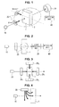
- FIG. 1 is a schematic perspective view illustrating the configuration of a biosensor according to a first embodiment of the present invention.
- FIG. 2 is a configuration block diagram of a biosensor according to the first embodiment of the present invention.
- a biosensor of the first embodiment of the present invention mainly includes a light source 10, magnetic field generation units 20, a light receiving unit 30, and a detection unit 40.
- an optical system including a collimator lens and a condensing lens is appropriately used when necessary.
- the dispersion liquid 1 is stored in an optically transparent container 2.
- the term "optically transparent” as used in the present specification means allowing the light from the light source 10 to pass therethrough in an excellent manner in a wavelength region used by an optical system that is used to detect a biomaterial; and does not necessarily mean having transparency in the entire wavelength region.
- the target biomaterial is a so-called antigen, which is for example made up of an oligosaccharide, a peptide and the like.
- Surface treatment is applied to the magnetic microparticles contained in the dispersion liquid 1 so that the biomaterial can bind to. All that is required is for a material that binds specifically to the biomaterial, such as an antibody, to be provided on the surfaces of the magnetic microparticles.
- a probe consisting of a sulfur atom and a thiol group is fixed; an oligosaccharide, which turns out to be a target biomaterial to which biotin is attached, is so structured as to bind to the probe.
- the surface treatment is not necessarily applied in such a way that the biomaterial can bind to all the magnetic microparticles.
- the magnetic microparticles are not specifically restricted. However, it is preferred that the particle diameters of the magnetic microparticles be 100 nm or less, about a size equivalent to unimolecular DNA, for example. Such a size reduces the difference in size between the magnetic microparticles and the biomaterial, making it easier for the magnetic microparticles and the biomaterial to bind to each other.
- the magnetic microparticles may be ferromagnetic or paramagnetic, and may be ferrite, alnico or the like. More specifically, the magnetic microparticles made of various magnetic materials, including the following, are available: FePt, Co, Ni, Fe, MnSb, and MnAs. In addition, it is possible to use commercially available magnetic microparticles. For example, it is possible to use magnetic microparticles with a particle diameter of 1 ⁇ m, such as Dynabeads MyOne Streptavidin manufactured by Invitrogen Corporation.
- a magnetic field is applied by a magnet, coil or the like. Then, along a direction in which the magnetic field is applied, a plurality of magnetic microparticles are adsorbed in the shape of a column, and a plurality of magnetic microparticle chains are formed as a result.
- a phenomenon is described, for example, " Field-induced Structures in Ferrofluid Emulsions", Jing Liu et al., Physical Review Letters, Vol. 74, No. 14, April 3, 1995 .
- the light source 10 is designed to emit a predetermined wavelength of light to the dispersion liquid 1.
- a source capable of emitting infrared light may be used, for example.
- a white light source, a filter, and the like may be used in combination.
- the magnetic field generation units 20 are designed to apply a magnetic field, a direction of which changes at least in two directions, to the dispersion liquid 1.
- the magnetic field generation units 20 are made from two electromagnets, the electromagnets are so controlled as to be turned ON and OFF alternately. As a result, it is possible to alternately apply a 0-degree and a 90-degree magnetic field to the dispersion liquid 1.
- the magnetic field generation units 20 may be able to apply a rotating magnetic field to the dispersion liquid 1.
- FIG. 3 is a top view illustrating magnetic field generation units that can apply a rotating magnetic field to the dispersion liquid.
- the dispersion liquid 1 is positioned at the center, and electromagnets 20 1 to 20 4 are disposed every 90 degrees so as to face each other.
- the electromagnets 20 1 to 20 4 are so structured as to alternately apply a magnetic field in four directions.
- a rotating magnetic field is applied to the dispersion liquid 1.
- the rotating magnetic field may be appropriately rotated at a speed that does not divide the magnetic microparticle chains.
- the direction of the applied magnetic field and the direction of the light emitted from the light source 10 be directions within the same plane.
- the light may be emitted to the dispersion liquid 1 from a hole at a central portion of an electromagnet of the magnetic field generation unit 20.
- FIG. 4 which is a side view illustrating another way of disposing a magnetic field generation unit, the magnetic field generation unit 20 may be so disposed that the axis of a magnet of the magnetic field generation unit 20 is perpendicular to an optical axis of the light source 10.
- the structure is possible that enables a magnetic flux that extends laterally to be applied into the same plane as the optical axis of the light source 10 relative to the dispersion liquid 1. Since the direction of the applied magnetic field and the direction of the light emitted from the light source are within the same side surface, the amount of change of the transmitted light, which will be described later, becomes larger.
- the intensity of the magnetic field of the magnetic field generation unit 20 varies according to magnetic properties of the magnetic microparticles, such as magnetic moment.
- the intensity may be set appropriately by taking into account the following: the size of a magnetic microparticle chain that can be formed, and the magnetic field intensity at which the magnetic microparticles do not precipitate.
- the applied magnetic field may be up to about 71.6 kA/m (about 900 Oe). Even with a smaller magnetic field, a magnetic microparticle column can be formed.
- the light receiving unit 30 is designed to receive the transmitted light from the dispersion liquid 1.
- the light receiving unit 30 may be so formed as to include a photodiode and the like.
- the light receiving unit 30 may be so formed as to receive only a light beam of an optical-axis direction from the light source 10 out of the transmitted light from the dispersion liquid; or alternatively, the light receiving unit 30 may be so formed as to receive the scattered light emitted from the dispersion liquid.
- the detection unit 40 is designed to detect the amount of change in the quantity of the transmitted light received by the light receiving unit 30, and detect whether or not a target biomaterial exists based on the detection results.
- the amount of change in the quantity of the transmitted light detected by the detection unit 40 will be described in detail.
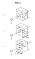
- FIG. 5 is a schematic perspective view illustrating changes of magnetic microparticles contained in the dispersion liquid 1.
- FIG. 5(a) shows the situation where no magnetic field is applied.
- FIG. 5(b) shows the case where a magnetic field is applied in a 0-degree direction.
- FIG. 5(c) shows the case where a magnetic field is applied in a 90-degree direction.
- there is some exaggeration in the drawings as to the size of the magnetic microparticles in a way that makes clear the motion of the magnetic microparticles.
- the magnetic microparticles are dispersed in the dispersion liquid 1.
- a magnetic field is applied, as shown in FIGS. 5(b) and 5(c) , a plurality of magnetic microparticles are adsorbed in the shape of a column along the direction of the applied magnetic field, and a plurality of magnetic microparticle chains are formed.
- the lengths of the magnetic microparticle chains vary depending on whether or not a biomaterial exists in the dispersion liquid 1. If a biomaterial exists in the dispersion liquid 1, the biomaterial binds to the antibody of a magnetic microparticle.
- the magnetic microparticle chains become longer in length.
- the differences in length affect the amount of change in the quantity of the transmitted light that has passed through the dispersion liquid 1 from the light source 10 at a time when the direction of the magnetic field is changed. Therefore, by measuring the amount of change, it is possible to detect whether or not a target biomaterial exists.
- FIG. 6 shows a graph illustrating the differences in the amount of change in the quantity of the transmitted light, which occur depending on whether or not a target biomaterial exists.
- the drawing shows changes in the quantity of the transmitted light received by the light receiving unit at a time when a rotating magnetic field was applied to the dispersion liquid.
- the horizontal axis represents time.
- the light source used was able to emit light with a wavelength of 630 nm; the magnetic microparticles used were 130 nm in particle diameter.
- avidin was used.
- FIG. 6 shows the quantity of the transmitted light at a time when a rotating magnetic field was applied to a dispersion liquid from magnetic field generation units under the above conditions.
- the intensity of the rotating magnetic field was about 955 A/m (12 Oe); the rotational frequency was 0.1 Hz.
- USB2000 manufactured by Ocean Optics, Inc.
- the transmitted light quantity was measured under the above conditions. As shown in the drawing, there were changes in the amount of change in the quantity of the transmitted light between when the target biomaterial existed and when the target biomaterial did not exist. More specifically, under the above-noted conditions, the amount of change in the quantity of the transmitted light was smaller when the target biomaterial existed than when the target biomaterial did not. Accordingly, the detection unit is able to detect whether or not the target biomaterial exists by detecting the amount of change (amplitude) in the quantity of the transmitted light received.
- the detection unit is also able to detect whether or not the target biomaterial exists by detecting the quantity (level) of the transmitted light quantity.
- a difference of detection results before and after the introduction of a sample may be used to detect whether or not the target biomaterial exists; or alternatively, a calibration curve may be created in advance with the use of a known sample so that the calibration curve can be used to detect whether or not the target biomaterial of an unknown sample exists.
- FIG. 7 shows a graph illustrating the differences in the amount of change in the quantity of the transmitted light, which occur depending on whether or not a target biomaterial exists under other conditions.
- the drawing shows the changes in the transmitted light quantity at a time when the light source used was able to emit light with a wavelength of 785 nm, and when the particle diameter of the magnetic microparticles used was 250 nm.
- USB2000 manufactured by Ocean Optics, Inc.
- the amount of change in the quantity of the transmitted light was larger when the target biomaterial existed than when the target biomaterial did not.
- the transmitted light quantity was smaller when the target biomaterial existed than when the target biomaterial did not.
- the biosensor of the first embodiment of the present invention changes the direction of a magnetic field when applying the magnetic field to the dispersion liquid under predetermined conditions, the amount of change in the quantity of the transmitted light is caused by a direction change of the magnetic field. Therefore, using the amount of change described above, it is possible to detect the existence of the target biomaterial.
- the length of a magnetic microparticle chain formed becomes longer as the concentration of the target biomaterial rises. Therefore, it is possible to detect not only whether or not the target biomaterial exists but also the concentration thereof.
- the biosensor of the first embodiment of the present invention changes the direction of the magnetic field, causing the magnetic microparticle chains to be shaken. Therefore, there is also an effect of stirring the dispersion liquid. As a result, compared with the case where a magnetic field is simply applied in one direction, it is also possible to ensure that the target biomaterial easily binds to the magnetic microparticles.
- the magnetic field generation units are not limited to those described above, which apply a rotating magnetic field.
- the direction of the magnetic field applied by the magnetic field generation units all that is required is for the magnetic field to change at least in two directions so that the amount of change in the quantity of the transmitted light can be measured.
- the two directions 0 and 90 degrees, realize the situation where the largest amount of change can be measured.
- the differences in the amount of change in the quantity of the transmitted light appeared immediately after the magnetic field was applied. Therefore, it is sufficient for the biosensor of the present invention to measure the transmitted light quantity at least in the following two situations: the transmitted light quantity at a time when the magnetic field is applied in one direction, and the transmitted light quantity at a time when the magnetic field is applied in another one direction. Therefore, it takes a very short period of time to detect whether or not the target biomaterial exists.
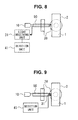
- FIG. 8 is a schematic perspective view illustrating the configuration of a biosensor according to the second embodiment of the present invention.
- the portions indicated by the same reference symbols as those in FIG. 1 represent substantially the same components. Therefore, the detailed description of the components will be omitted.
- the biosensor of the second embodiment the light emitted from the light source 10 enters the dispersion liquid 1.
- the biosensor includes a light receiving unit 31 that receives the light reflected from the dispersion liquid.
- a detection unit 41 detects whether or not the target biomaterial exists based on the amount of change in the quantity of the reflected light received by the light receiving unit 31.
- the quantity of the reflected light is caused by a direction change of a magnetic field applied by the magnetic field generation units 20.
- the reaction is opposite to that of the transmitted light quantity. Accordingly, even when the reflected light quantity is used, as in the case where the transmitted light quantity is used, it is possible to detect whether or not the target biomaterial exists.
- the light from the light source 10 is emitted to the dispersion liquid 1 using an optical waveguide 50, such as optical fiber.
- the structure here allows the reflected light to enter the light receiving unit 31 via the optical waveguide 50.
- the optical waveguide 50 is formed by bundling a plurality of optical fibers, one central fiber of the bundle is connected to the light receiving unit 31, and the other peripheral optical fibers are connected to the light source 10.
- R400-7-VIS-NIR manufactured by Ocean Optics, Inc.
- the light receiving unit 31 may be so formed that a photoelectric conversion device, such as CCD, is directly disposed on a dispersion liquid-side tip of the optical waveguide 50.
- the biosensor of the present invention it is possible to detect whether or not the target biomaterial exists with high levels of sensitivity. That is, if a sensor is designed to measure the magnetism of magnetic microparticles and therefore detect whether or not a target biomaterial exists in the same way as a conventional technique, it could not be possible to detect because of the insufficient sensitivity of the magnetic sensor at a time when the magnetic microparticles are small in diameter and when the magnetism is extremely small.
- the biosensor of the present invention is not intended to measure the magnetism. Based on change in the transmitted or reflected light, the biosensor of the present invention is able to detect whether or not the target biomaterial exists. As a result, compared with a conventional technique, higher-sensitivity measurement is possible.
- biosensor of the present invention that uses the magnetic microparticles is not limited to those in the above embodiments shown in the drawings. Needless to say, various changes may be made without departing from the subject-matter of the present invention.
- the measurement conditions, the measurement results, and the like are only one specific embodiment among many and the present invention is not limited thereto.
Landscapes
- Health & Medical Sciences (AREA)
- Immunology (AREA)
- Life Sciences & Earth Sciences (AREA)
- Chemical & Material Sciences (AREA)
- Engineering & Computer Science (AREA)
- Biochemistry (AREA)
- Molecular Biology (AREA)
- General Physics & Mathematics (AREA)
- Physics & Mathematics (AREA)
- Pathology (AREA)
- Analytical Chemistry (AREA)
- Biomedical Technology (AREA)
- General Health & Medical Sciences (AREA)
- Urology & Nephrology (AREA)
- Hematology (AREA)
- Biotechnology (AREA)
- Microbiology (AREA)
- Cell Biology (AREA)
- Food Science & Technology (AREA)
- Medicinal Chemistry (AREA)
- Investigating Or Analysing Materials By Optical Means (AREA)
Applications Claiming Priority (2)
| Application Number | Priority Date | Filing Date | Title |
|---|---|---|---|
| JP2009240268 | 2009-10-19 | ||
| PCT/JP2010/068273 WO2011049044A1 (ja) | 2009-10-19 | 2010-10-18 | 磁性微粒子を用いるバイオセンサ |
Publications (1)
| Publication Number | Publication Date |
|---|---|
| EP2492665A1 true EP2492665A1 (de) | 2012-08-29 |
Family
ID=43900270
Family Applications (1)
| Application Number | Title | Priority Date | Filing Date |
|---|---|---|---|
| EP10824893A Withdrawn EP2492665A1 (de) | 2009-10-19 | 2010-10-18 | Biosensor mit magnetischen mikropartikeln |
Country Status (4)
| Country | Link |
|---|---|
| US (1) | US20120251392A1 (de) |
| EP (1) | EP2492665A1 (de) |
| JP (1) | JPWO2011049044A1 (de) |
| WO (1) | WO2011049044A1 (de) |
Cited By (1)
| Publication number | Priority date | Publication date | Assignee | Title |
|---|---|---|---|---|
| US9784735B2 (en) | 2013-06-28 | 2017-10-10 | Danmarks Tekniske Universitet | Biosensor based on the measurements of clustering dynamics of magnetic particles using a double pass setup |
Families Citing this family (5)
| Publication number | Priority date | Publication date | Assignee | Title |
|---|---|---|---|---|
| EP2541230A1 (de) | 2011-06-30 | 2013-01-02 | Koninklijke Philips Electronics N.V. | Erkennung von Clustern aus magnetischen Partikeln |
| GB201115120D0 (en) | 2011-09-01 | 2011-10-19 | Univ Exeter | Method and device for detecting an analyte |
| US9863863B2 (en) * | 2011-11-14 | 2018-01-09 | Koninklijke Philips N.V. | Apparatus for cluster detection |
| US20240003806A1 (en) * | 2020-11-10 | 2024-01-04 | Chromologic Llc | System and method for extracting and detecting a paramagnetic material from an aqueous medium |
| KR102927687B1 (ko) * | 2021-05-07 | 2026-02-13 | 오다이라 래보로토리 캄파니 | 미세 기포 분산액의 측정 방법 및 측정 시스템 |
Family Cites Families (24)
| Publication number | Priority date | Publication date | Assignee | Title |
|---|---|---|---|---|
| JPS62118255A (ja) * | 1985-11-19 | 1987-05-29 | Toshimitsu Musha | 磁界を用いた免疫反応の検出法 |
| US4849340A (en) * | 1987-04-03 | 1989-07-18 | Cardiovascular Diagnostics, Inc. | Reaction system element and method for performing prothrombin time assay |
| JPH07111430B2 (ja) * | 1987-10-22 | 1995-11-29 | 日本電信電話株式会社 | レーザ磁気免疫測定方法及び測定装置 |
| JPH01244371A (ja) * | 1988-03-25 | 1989-09-28 | Olympus Optical Co Ltd | 特異結合反応の測定方法 |
| JPH05240859A (ja) | 1991-11-28 | 1993-09-21 | Fujirebio Inc | 凝集免疫測定方法及び装置 |
| US6337215B1 (en) * | 1997-12-01 | 2002-01-08 | International Business Machines Corporation | Magnetic particles having two antiparallel ferromagnetic layers and attached affinity recognition molecules |
| US7015047B2 (en) * | 2001-01-26 | 2006-03-21 | Aviva Biosciences Corporation | Microdevices having a preferential axis of magnetization and uses thereof |
| FR2832507B1 (fr) * | 2001-11-20 | 2004-02-20 | Stago Diagnostica | Methode de detection d'analyte(s) a l'aide de particules magnetiques colloidales |
| US7226414B2 (en) * | 2002-10-09 | 2007-06-05 | Biotex, Inc. | Method and apparatus for analyte sensing |
| JP2006071300A (ja) * | 2004-08-31 | 2006-03-16 | Hitachi Ltd | 生化学物質検出装置 |
| JP5311445B2 (ja) * | 2005-01-31 | 2013-10-09 | コーニンクレッカ フィリップス エヌ ヴェ | 高速かつ高感度バイオセンシング |
| JP2006247535A (ja) * | 2005-03-10 | 2006-09-21 | Toyo Univ | 回転磁場を利用した反応促進方法 |
| CN101198870A (zh) * | 2005-06-17 | 2008-06-11 | 皇家飞利浦电子股份有限公司 | 精密磁性生物传感器 |
| JP5000666B2 (ja) * | 2006-01-25 | 2012-08-15 | コーニンクレッカ フィリップス エレクトロニクス エヌ ヴィ | 流体を分析する装置 |
| WO2007110756A2 (en) * | 2006-03-28 | 2007-10-04 | Inverness Medical Switzerland Gmbh | Assay device and method with magnetic field and time-varying signals |
| WO2008008257A2 (en) * | 2006-07-07 | 2008-01-17 | It Au0801213 | Oriented magnetic particle-fluorescence detectable moiety compositions and methods of making and using the same |
| JP2008128677A (ja) * | 2006-11-16 | 2008-06-05 | Tokyo Institute Of Technology | バイオセンサ用マーカ、バイオセンサ、及びバイオセンサ用マーカ検出方法 |
| RU2487338C2 (ru) * | 2006-12-12 | 2013-07-10 | Конинклейке Филипс Электроникс Н.В. | Микроэлектронное сенсорное устройство для обнаружения частиц-меток |
| WO2009061865A1 (en) * | 2007-11-07 | 2009-05-14 | Siemens Heathcare Diagnostics Inc. | A method and apparatus for increasing the sensitivity of a biosensor used in a planar waveguide |
| CN101925818A (zh) * | 2008-01-28 | 2010-12-22 | 皇家飞利浦电子股份有限公司 | 用于外部驱动生物传感器盒中的磁性粒子的生物传感器系统 |
| WO2009098623A1 (en) * | 2008-02-06 | 2009-08-13 | Koninklijke Philips Electronics N.V. | Magnetic bead actuation using feedback for ftir biosensor |
| US20090220380A1 (en) * | 2008-03-01 | 2009-09-03 | Daniel Joel Brown | Wireless electronic monitor for a container such as an aquarium and the like |
| EP2108938A1 (de) * | 2008-04-09 | 2009-10-14 | Koninklijke Philips Electronics N.V. | Träger für optische Detektion bei kleinen Probenvolumen |
| JP2010071693A (ja) * | 2008-09-16 | 2010-04-02 | Fujifilm Corp | センシング方法、センシング装置、検査チップおよび検査キット |
-
2010
- 2010-10-18 EP EP10824893A patent/EP2492665A1/de not_active Withdrawn
- 2010-10-18 US US13/502,707 patent/US20120251392A1/en not_active Abandoned
- 2010-10-18 JP JP2011537239A patent/JPWO2011049044A1/ja active Pending
- 2010-10-18 WO PCT/JP2010/068273 patent/WO2011049044A1/ja not_active Ceased
Non-Patent Citations (1)
| Title |
|---|
| See references of WO2011049044A1 * |
Cited By (1)
| Publication number | Priority date | Publication date | Assignee | Title |
|---|---|---|---|---|
| US9784735B2 (en) | 2013-06-28 | 2017-10-10 | Danmarks Tekniske Universitet | Biosensor based on the measurements of clustering dynamics of magnetic particles using a double pass setup |
Also Published As
| Publication number | Publication date |
|---|---|
| WO2011049044A1 (ja) | 2011-04-28 |
| US20120251392A1 (en) | 2012-10-04 |
| JPWO2011049044A1 (ja) | 2013-03-14 |
Similar Documents
| Publication | Publication Date | Title |
|---|---|---|
| JP6205041B2 (ja) | マイクロエレクトロニクスセンサデバイス、読み取り装置及び検出方法 | |
| US9841421B2 (en) | Sensor device for magnetically actuated particles | |
| EP3450961B1 (de) | Optisches detektionsverfahren und optische detektionsvorrichtung | |
| EP2225547B1 (de) | Mikroelektronische sensorvorrichtung zur erkennung von zielpartikeln | |
| JP5628784B2 (ja) | 磁性粒子によるアッセイ用カートリッジ | |
| US8970215B2 (en) | Sensor device for and a method of sensing particles | |
| US20100188076A1 (en) | Microelectronic sensor device with magnetic field generator and carrier | |
| EP2467722B1 (de) | Nachweis verschiedener zielkomponenten durch aggregat-bildung | |
| US20120251392A1 (en) | Biosensor Using Magnetic Microparticles | |
| US20120202194A1 (en) | Substance determining apparatus | |
| JP6225114B2 (ja) | クラスタ検出に関する装置 | |
| US20100221842A1 (en) | Sensor device for the detection of target components | |
| EP2726848B1 (de) | Erkennung von clustern aus magnetischen partikeln | |
| JP4911471B2 (ja) | バイオセンサ用マーカ、バイオセンサ、及びバイオセンサ用マーカ検出方法 | |
| JP7455529B2 (ja) | 検体測定装置及び検体測定装置の制御方法 | |
| JP5766642B2 (ja) | 測定方法、センサチップ、および測定装置 | |
| JP2014025879A (ja) | センサーチップおよびこのセンサーチップを備えた光学式検体検出装置 | |
| JP2008128677A (ja) | バイオセンサ用マーカ、バイオセンサ、及びバイオセンサ用マーカ検出方法 | |
| EP1972927A1 (de) | Mikroelektronische Sensorvorrichtung zum Erkennen von Markierungspartikeln | |
| EP2584338A1 (de) | Erkennung von Clustern aus magnetischen Partikeln | |
| US8529837B2 (en) | System and method for detecting specific binding reactions using magnetic labels | |
| JP2020190428A (ja) | 標的物質の計数方法、計数装置 |
Legal Events
| Date | Code | Title | Description |
|---|---|---|---|
| PUAI | Public reference made under article 153(3) epc to a published international application that has entered the european phase |
Free format text: ORIGINAL CODE: 0009012 |
|
| 17P | Request for examination filed |
Effective date: 20120423 |
|
| AK | Designated contracting states |
Kind code of ref document: A1 Designated state(s): AL AT BE BG CH CY CZ DE DK EE ES FI FR GB GR HR HU IE IS IT LI LT LU LV MC MK MT NL NO PL PT RO RS SE SI SK SM TR |
|
| DAX | Request for extension of the european patent (deleted) | ||
| STAA | Information on the status of an ep patent application or granted ep patent |
Free format text: STATUS: THE APPLICATION HAS BEEN WITHDRAWN |
|
| 18W | Application withdrawn |
Effective date: 20150811 |