EP2492912B1 - Appareil de traitement du son, procédé de traitement du son et prothèse auditive - Google Patents
Appareil de traitement du son, procédé de traitement du son et prothèse auditive Download PDFInfo
- Publication number
- EP2492912B1 EP2492912B1 EP10824665.3A EP10824665A EP2492912B1 EP 2492912 B1 EP2492912 B1 EP 2492912B1 EP 10824665 A EP10824665 A EP 10824665A EP 2492912 B1 EP2492912 B1 EP 2492912B1
- Authority
- EP
- European Patent Office
- Prior art keywords
- section
- utterer
- level
- sound
- directivity
- Prior art date
- Legal status (The legal status is an assumption and is not a legal conclusion. Google has not performed a legal analysis and makes no representation as to the accuracy of the status listed.)
- Active
Links
Images









Classifications
-
- H—ELECTRICITY
- H04—ELECTRIC COMMUNICATION TECHNIQUE
- H04R—LOUDSPEAKERS, MICROPHONES, GRAMOPHONE PICK-UPS OR LIKE ACOUSTIC ELECTROMECHANICAL TRANSDUCERS; ELECTRIC HEARING AIDS; PUBLIC ADDRESS SYSTEMS
- H04R25/00—Electric hearing aids
- H04R25/40—Arrangements for obtaining a desired directivity characteristic
- H04R25/407—Circuits for combining signals of a plurality of transducers
-
- G—PHYSICS
- G10—MUSICAL INSTRUMENTS; ACOUSTICS
- G10L—SPEECH ANALYSIS TECHNIQUES OR SPEECH SYNTHESIS; SPEECH RECOGNITION; SPEECH OR VOICE PROCESSING TECHNIQUES; SPEECH OR AUDIO CODING OR DECODING
- G10L21/00—Speech or voice signal processing techniques to produce another audible or non-audible signal, e.g. visual or tactile, in order to modify its quality or its intelligibility
- G10L21/02—Speech enhancement, e.g. noise reduction or echo cancellation
- G10L21/0316—Speech enhancement, e.g. noise reduction or echo cancellation by changing the amplitude
- G10L21/0364—Speech enhancement, e.g. noise reduction or echo cancellation by changing the amplitude for improving intelligibility
-
- G—PHYSICS
- G10—MUSICAL INSTRUMENTS; ACOUSTICS
- G10L—SPEECH ANALYSIS TECHNIQUES OR SPEECH SYNTHESIS; SPEECH RECOGNITION; SPEECH OR VOICE PROCESSING TECHNIQUES; SPEECH OR AUDIO CODING OR DECODING
- G10L21/00—Speech or voice signal processing techniques to produce another audible or non-audible signal, e.g. visual or tactile, in order to modify its quality or its intelligibility
- G10L21/02—Speech enhancement, e.g. noise reduction or echo cancellation
- G10L21/0208—Noise filtering
- G10L21/0216—Noise filtering characterised by the method used for estimating noise
- G10L2021/02161—Number of inputs available containing the signal or the noise to be suppressed
- G10L2021/02165—Two microphones, one receiving mainly the noise signal and the other one mainly the speech signal
-
- G—PHYSICS
- G10—MUSICAL INSTRUMENTS; ACOUSTICS
- G10L—SPEECH ANALYSIS TECHNIQUES OR SPEECH SYNTHESIS; SPEECH RECOGNITION; SPEECH OR VOICE PROCESSING TECHNIQUES; SPEECH OR AUDIO CODING OR DECODING
- G10L21/00—Speech or voice signal processing techniques to produce another audible or non-audible signal, e.g. visual or tactile, in order to modify its quality or its intelligibility
- G10L21/02—Speech enhancement, e.g. noise reduction or echo cancellation
- G10L21/0208—Noise filtering
- G10L21/0216—Noise filtering characterised by the method used for estimating noise
- G10L2021/02161—Number of inputs available containing the signal or the noise to be suppressed
- G10L2021/02166—Microphone arrays; Beamforming
-
- G—PHYSICS
- G10—MUSICAL INSTRUMENTS; ACOUSTICS
- G10L—SPEECH ANALYSIS TECHNIQUES OR SPEECH SYNTHESIS; SPEECH RECOGNITION; SPEECH OR VOICE PROCESSING TECHNIQUES; SPEECH OR AUDIO CODING OR DECODING
- G10L21/00—Speech or voice signal processing techniques to produce another audible or non-audible signal, e.g. visual or tactile, in order to modify its quality or its intelligibility
- G10L21/06—Transformation of speech into a non-audible representation, e.g. speech visualisation or speech processing for tactile aids
- G10L2021/065—Aids for the handicapped in understanding
-
- G—PHYSICS
- G10—MUSICAL INSTRUMENTS; ACOUSTICS
- G10L—SPEECH ANALYSIS TECHNIQUES OR SPEECH SYNTHESIS; SPEECH RECOGNITION; SPEECH OR VOICE PROCESSING TECHNIQUES; SPEECH OR AUDIO CODING OR DECODING
- G10L25/00—Speech or voice analysis techniques not restricted to a single one of groups G10L15/00 - G10L21/00
- G10L25/78—Detection of presence or absence of voice signals
-
- H—ELECTRICITY
- H04—ELECTRIC COMMUNICATION TECHNIQUE
- H04R—LOUDSPEAKERS, MICROPHONES, GRAMOPHONE PICK-UPS OR LIKE ACOUSTIC ELECTROMECHANICAL TRANSDUCERS; ELECTRIC HEARING AIDS; PUBLIC ADDRESS SYSTEMS
- H04R2225/00—Details of deaf aids covered by H04R25/00, not provided for in any of its subgroups
- H04R2225/43—Signal processing in hearing aids to enhance the speech intelligibility
Definitions
- the present invention relates to a sound processing apparatus, a sound processing method and a hearing aid, capable of allowing the user to easily hear the sound of an utterer close to the user by emphasizing the sound of the utterer close to the user relative to the sound of an utterer far away from the user.
- Patent Document 1 is an example of a sound processing apparatus for emphasizing only the sound of an utterer close to the user. According to Patent document 1, near-field sound is emphasized by using the amplitude ratio of the sound input to microphones disposed away from each other by appropriately 50 [cm] to 1 [m] and on the basis of a weighting function that has been calculated in advance so as to correspond to the amplitude ratio.
- FIG. 30 is a block diagram showing an internal configuration of the sound processing apparatus disclosed in Patent document 1.
- a divider 1614 the amplitude value of a microphone 1601A calculated by a first amplitude extractor 1613A and the amplitude value of a microphone 1601B calculated by a second amplitude extractor 1613B are input.
- the divider 1614 obtains the amplitude ratio between the microphones A and B on the basis of the amplitude value of the microphone 1601A and the amplitude value of the microphone 1601B.
- a coefficient calculator 1615 calculates a weighting coefficient corresponding to the amplitude ratio calculated by the divider 1614.
- a near-field sound source separation apparatus 1602 is configured to emphasize near-field sound by using the weighting function that has been calculated in advance according to the amplitude ratio calculated by the coefficient calculator 1615.
- Patent document 2 describes a speaker distance detection apparatus, for instance for a mobile phone.
- the apparatus comprises a microphone array having at least two microphones which are assumed to have different distances to the sound source and out of which one is set as a reference microphone. Differences between a signal level of the reference microphone and of the other microphone(s) are determined based on correlations between signals, and the distance from the microphone array to the sound source is determined based thereon.
- a first microphone may be arranged on a front cover thereof, and a second microphone on a back cover.
- Directivity speech reception processing is performed so as to generate a strong directivity in the direction of the sound source, and a level control is performed so that a gain is set to be smaller when the distance is shorter and the gain is larger when the distance is longer.
- Patent document 3 describes a method and an apparatus for determining the distance between a pair of microphones and an acoustic source, for instance in hands-free telecommunication wherein it is usually intended to process only the voice of the speaker close to the microphone and ignore background noise.
- the distance is determined by analyzing the direct-to-reverberant ratio (DTR) between the sound directly received from the sound source and the reverberant sound.
- the ratio is determined from the angular acoustic power distribution, wherein an angle of incidence of acoustic power is determined by comparing the time lag between the input from the two microphones.
- DTR direct-to-reverberant ratio
- the apparatus 1602 in the case that the sound of a sound source or an utterer close to the user is desired to be emphasized by using the above-mentioned near-field sound source separation apparatus 1602, a large amplitude ratio is required to be obtained between the microphones 1601A and 1601B. For this reason, the two microphones 1601A and 1601B are required to be disposed so that a considerably large distance is provided therebetween. Hence, it is difficult to apply the apparatus to a compact sound processing apparatus in which microphones are disposed so that the distance therebetween is particularly in a range of several [mm] (millimeters) to several [cm] (centimeters).
- the amplitude ratio between the two microphones becomes small; hence, it is difficult to properly distinguish between a sound source or an utterer close to the user and a sound source or an utterer far away from the user.
- an object of the present invention is to provide a sound processing apparatus, a sound processing method and a hearing aid, for efficiently emphasizing the sound of an utterer close to the user regardless of the distance between microphones.
- the sound processing apparatus the sound processing method and the hearing aid of the present invention
- the sound of the utterer close to the user can be efficiently emphasized irrespective of the distance between the microphones.
- the "first”, “fifth” and “sixth” embodiments are comparative examples only.
- the second to fourth embodiments are embodiments of the present invention.
- FIG. 1 is a block diagram showing an internal configuration of a sound processing apparatus 10 according to a first embodiment.
- the sound processing apparatus 10 has a first directional microphone 101, a second directional microphone 102, a first level calculation section 103, a second level calculation section 104, an utterer distance determination section 105, a gain derivation section 106, and a level control section 107.
- the first directional microphone 101 is a unidirectional microphone having the main axis of directivity in the direction of the utterer and mainly picks up the direct sound of the sound of the utterer.
- the first directional microphone 101 outputs this picked-up sound signal x1(t) to each of the first level calculation section 103 and the level control section 107.
- the second directional microphone 102 is a unidirectional microphone or a bidirectional microphone having a directional dead zone in the direction of the utterer, does not pick up the direct sound of the sound of the utterer, but picks up the reverberant sound of the sound of the utterer mainly generated by the reflection from the wall or the like of a room.
- the second directional microphone 102 outputs this picked-up sound signal x2(t) to the second level calculation section 104.
- the distance between the first directional microphone 101 and the second directional microphone 102 is a distance of approximately several [mm] to several [cm].
- the first level calculation section 103 obtains the sound signal x1(t) output from the first directional microphone 101 and calculates the level Lx1(t) [dB] of the obtained sound signal x1(t).
- the first level calculation section 103 outputs the level Lx1(t) of the calculated sound signal x1(t) to the utterer distance determination section 105.
- Mathematical expression (1) shows an example of the calculation expression of the level Lx1(t) that is calculated by the first level calculation section 103.
- N is the number of samples required for the level calculation.
- the sampling frequency is 8 [kHz] and that the analysis time for the level calculation is 20 [ms]
- T represents a time constant, has a value in the range of 0 ⁇ T ⁇ 1 and has been determined in advance.
- FIG. 2 shows the waveform of the sound output from the first directional microphone 101 and the level Lx1(t) obtained when the first level calculation section 103 performed calculation.
- the level Lx1(t) is an example calculated by the first level calculation section 103 in the case that the time constant in the case of Mathematical expression (2) is 100 [ms] and that the time constant in the case of Mathematical expression (3) is 400 [ms].
- FIG. 2(a) is a view showing the time change in the waveform of the sound output from the first directional microphone 101
- FIG. 2(b) is a view showing the time change in the level calculated by the first level calculation section 103.
- the vertical axis represents amplitude
- the horizontal axis represents time [sec].
- the vertical axis represents level
- the horizontal axis represents time [sec].
- the second level calculation section 104 obtains the sound signal x2(t) output from the second directional microphone 102 and calculates the level Lx2(t) of the obtained sound signal x2(t).
- the second level calculation section 104 outputs the calculated level Lx2(t) of the sound signal x2(t) to the utterer distance determination section 105.
- the calculation expression of the level Lx2(t) calculated by the second level calculation section 104 is the same as Mathematical expression (1) by which the level Lx1(t) is calculated.
- FIG. 3 shows the waveform of the sound output from the second directional microphone 102 and the level Lx2(t) obtained when calculation is performed by the second level calculation section 104.
- the level Lx2(t) is an example calculated by the second level calculation section 104 in the case that the time constant in the case of Mathematical expression (2) is 100 [ms] and that the time constant in the case of Mathematical expression (3) is 400 [ms].
- FIG. 3(a) is a view showing the time change in the waveform of the sound output from the second directional microphone 102. Furthermore, FIG. 3(b) is a view showing the time change in the level calculated by the second level calculation section 104.
- the vertical axis represents amplitude
- the horizontal axis represents time [sec].
- the vertical axis represents level
- the horizontal axis represents time [sec].
- the utterer distance determination section 105 obtains the level Lx1(t) of the sound signal x1(t) calculated by the first level calculation section 103 and the level Lx2(t) of the sound signal x2(t) calculated by the second level calculation section 103. On the basis of these obtained level Lx1(t) and level Lx2(t), the utterer distance determination section 105 determines whether the utterer is close to the user. The utterer distance determination section 105 outputs distance determination result information serving as the result of the determination to the gain derivation section 106.
- the utterer distance determination section 105 determines whether the utterer is close to the user.
- the distance indicating that the utterer is close to the user corresponds to a distance of 2 [m] or less between the utterer and the user.
- the distance indicating that the utterer is close to the user is not limited to the distance of 2 [m] or less.
- the utterer distance determination section 105 determines that the utterer is close to the user.
- the first threshold value ⁇ 1 is 12 [dB] for example.
- the utterer distance determination section 105 determines that the utterer is far away from the user.
- the second threshold value ⁇ 2 is 8 [dB] for example. Furthermore, in the case that the level difference ⁇ Lx(t) is equal to or more than the second threshold value ⁇ 2 and less than the first threshold value ⁇ 1, the utterer distance determination section 105 determines that the utterer is slightly away from the user.
- the utterer distance determination section 105 outputs distance determination result information "1" indicating that the utterer is close to the user to the gain derivation section 106.
- the distance determination result information "1" represents that the direct sound picked up by the first directional microphone 101 is abundant and that the reverberant sound picked up by the second directional microphone 102 is scarce.
- the utterer distance determination section 105 outputs distance determination result information "-1" indicating that the utterer is far away from the user.
- the distance determination result information "-1" represents that the direct sound picked up by the first directional microphone 101 is scarce and that the reverberant sound picked up by the second directional microphone 102 is abundant.
- the utterer distance determination section 105 outputs distance determination result information "0" indicating that the utterer is slightly away from the user.
- Determining the distance of the utterer on the basis of only the magnitude of the level Lx1(t) calculated by the first level calculation section 103 is not efficient in the accuracy of the determination. Due to the characteristics of the first directional microphone 101, when only the magnitude of the level Lx1(t) is used, it is difficult to determine the difference between a case in which a person far away from the user speaks at high volume and a case in which a person close to the user speaks at normal volume.
- the characteristics of the first and second directional microphones 101 and 102 are as described next. In the case that the utterer is close to the user, the sound signal x1(t) output from the first directional microphone 101 is relatively larger than the sound signal x2(t) output from the second directional microphone 102.
- the sound signal x1(t) output from the first directional microphone 101 is almost equal to the sound signal x2(t) output from the second directional microphone 102.
- this tendency becomes significant.
- the utterer distance determination section 105 does not determine whether the utterer is close to or far away from the user on the basis of only the magnitude of the level Lx1(t) calculated by the first level calculation section 103. Hence, the utterer distance determination section 105 determines the distance of the utterer on the basis of the difference between the level Lx1(t) of the sound signal x1(t) in which the direct sound is mainly picked up and the level Lx2(t) of the sound signal x2(t) in which the reverberant sound is mainly picked up.
- the gain derivation section 106 derives the gain ⁇ (t) corresponding to the sound signal x1(t) output from the first directional microphone 101 on the basis of the distance determination result information output from the utterer distance determination section 105.
- the gain derivation section 106 outputs the derived gain ⁇ (t) to the level control section 107.
- FIG. 4 is a view showing an example representing the relationship between the level difference ⁇ Lx(t) calculated by the utterer distance determination section 105 and the gain ⁇ (t).
- a gain ⁇ 1 is given as the gain ⁇ (t) corresponding to the sound signal x1(t). For example, when "2.0" is set as the gain ⁇ 1, the sound signal x1(t) is relatively emphasized.
- a gain ⁇ 2 is given as the gain ⁇ (t) corresponding to the sound signal x1(t). For example, when "0.5" is set as the gain ⁇ 2, the sound signal x1(t) is relatively attenuated.
- the sound signal x1(t) is not particularly emphasized or attenuated; hence, "1.0" is given as the gain ⁇ (t).
- the value derived as the gain ⁇ (t) in the above description is herein given as an instantaneous gain a'(t) to reduce the distortion that is generated in the sound signal x1(t) when the gain ⁇ (t) changes rapidly.
- the gain derivation section 106 finally calculates the gain ⁇ (t) according to Mathematical expression (4) described below.
- T ⁇ represents a time constant, has a value in the range of 0 ⁇ T ⁇ 1 and has been determined in advance.
- the level control section 107 obtains the gain ⁇ (t) derived according to Mathematical expression (4) described above by the gain derivation section 106 and the sound signal x1(t) output from the first directional microphone 101.
- the level control section 107 generates an output signal y(t) that is obtained by multiplying the gain ⁇ (t) derived by the gain derivation section 106 to the sound signal x1(t) output from the first directional microphone 101.
- FIG. 5 is a flowchart illustrating the operation of the sound processing apparatus 10 according to the first embodiment.
- the first directional microphone 101 picks up the direct sound of the sound of the utterer (at S101). Concurrently, the second directional microphone 102 picks up the reverberant sound of the sound of the utterer (at S102).
- the respective sound pickup processes of the first directional microphone 101 and the second directional microphone 102 are performed at the same timing.
- the first directional microphone 101 outputs the picked-up sound signal x1(t) to each of the first level calculation section 103 and the level control section 107.
- the second directional microphone 102 outputs the picked-up sound signal x2(t) to the second level calculation section 104.
- the first level calculation section 103 obtains the sound signal x1(t) output from the first directional microphone 101 and calculates the level Lx1(t) of the obtained sound signal x1(t) (at S103).
- the second level calculation section 104 obtains the sound signal x2(t) output from the second directional microphone 102 and calculates the level Lx2(t) of the obtained sound signal x2 (at S104).
- the first level calculation section 103 outputs the calculated level Lx1(t) to the utterer distance determination section 105. Furthermore, the second level calculation section 104 outputs the calculated level Lx2(t) to the utterer distance determination section 105.
- the utterer distance determination section 105 obtains the level Lx1(t) calculated by the first level calculation section 103 and the level Lx2(t) calculated by the second level calculation section 104.
- the utterer distance determination section 105 determines whether the utterer is close to the user on the basis of the level difference ⁇ Lx(t) between the level Lx1(t) and the level Lx2(t) obtained as described above (at S105).
- the utterer distance determination section 105 outputs the distance determination result information serving as the result of the determination to the gain derivation section 106.
- the gain derivation section 106 obtains the distance determination result information output from the utterer distance determination section 105.
- the gain derivation section 106 derives the gain ⁇ (t) corresponding to the sound signal x1(t) output from the first directional microphone 101 on the basis of the distance determination result information output from the utterer distance determination section 105 (at S106).
- the gain derivation section 106 outputs the derived gain ⁇ (t) to the level control section 107.
- the level control section 107 obtains the gain ⁇ (t) derived from the gain derivation section 106 and the sound signal x1(t) output from the first directional microphone 101.
- the level control section 107 generates the output signal y(t) that is obtained by multiplying the gain ⁇ (t) derived by the gain derivation section 106 to the sound signal x1(t) output from the first directional microphone 101 (at S107).
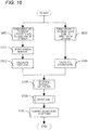
- FIG. 6 is a flowchart illustrating the details of the operation of the gain derivation section 106.
- the distance determination result information is "1", that is, in the case of the level difference ⁇ Lx ⁇ 1 (YES at S1061), "2.0” is derived as the instantaneous gain a'(t) corresponding to the sound signal x1(t) (at S1062).
- the distance determination result information is "-1", that is, in the case of the level difference ⁇ Lx ⁇ 2 (YES at S1063), "0.5” is derived as the instantaneous gain a'(t) corresponding to the sound signal x1(t) (at S1064).
- the gain derivation section 106 calculates the gain ⁇ (t) according to Mathematical expression (4) described above (at S1066).
- the determination as to whether the utterer is close to or far away from the user is made even in the case that the first and second directional microphones being disposed at a distance of approximately several [mm] to several [cm] therebetween are used. More specifically, in this embodiment, the distance of the utterer is determined according to the magnitude of the level difference ⁇ Lx(t) between the sound signals x1(t) and x2(t) picked up respectively by the first and second directional microphones being disposed at a distance of approximately several [mm] to several [cm] therebetween.
- the gain calculated according to the result of the determination is multiplied to the sound signal output to the first directional microphone for picking up the direct sound of the utterer, and the level is controlled.
- the sound of the utterer close to the user such as the conversational partner thereof, is emphasized; conversely, the sound of the utterer far away from the user is attenuated or suppressed.
- the sound of the conversational partner close to the user can be emphasized so as to be heard clearly and efficiently, regardless of the distance between the microphones.
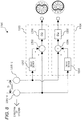
- FIG. 7 is a block diagram showing an internal configuration of a sound processing apparatus 11 according to a second embodiment.
- the same components as those shown in FIG. 1 are designated by the same reference codes and the descriptions of the components are omitted.
- the sound processing apparatus 11 has a directional sound pickup section 1101, the first level calculation section 103, the second level calculation section 104, the utterer distance determination section 105, the gain derivation section 106, and the level control section 107.
- the directional sound pickup section 1101 has a microphone array 1102, a first directivity forming section 1103, and a second directivity forming section 1104.
- the microphone array 1102 is an array in which a plurality of omnidirectional microphones are disposed.
- the configuration shown in FIG. 7 is an example in which an array is formed of two omnidirectional microphones.
- the distance D between the two omnidirectional microphones is a given value that is determined by restrictions in the required frequency band and installation space.
- the first directivity forming section 1103 forms directivity having the main axis of directivity in the direction of the utterer by using the sound signals output from the two omnidirectional microphones of the microphone array 1102 and mainly picks up the direct sound of the sound of the utterer.
- the first directivity forming section 1103 outputs the sound signal x1(t), the directivity of which has been formed, to each of the first level calculation section 103 and the level control section 107.
- the second directivity forming section 1104 forms directivity having the dead zone of directivity in the direction of the utterer by using the sound signals output from the two omnidirectional microphones of the microphone array 1102. Next, the second directivity forming section 1104 does not pick up the direct sound of the sound of the utterer but picks up the reverberant sound of the sound of the utterer mainly generated by the reflection from the wall or the like of a room.
- the second directivity forming section 1104 outputs the sound signal x2(t), the directivity of which has been formed, to the second level calculation section 104.
- FIG. 8 is a block diagram showing an internal configuration of the directional sound pickup section 1101 shown in FIG. 7 and illustrating the directivity forming method of the sound pressure gradient type. As shown in FIG. 8 , two omnidirectional microphones 1201-1 and 1201-2 are used for the microphone array 1102.
- the first level calculation section 1103 is formed of a delay device 1202, an arithmetic unit 1203, and an EQ 1204.
- the delay device 1202 obtains the sound signal output from the omnidirectional microphone 1201-2 and delays the obtained sound signal by a predetermined amount.
- the amount of the delay by the delay device 1202 is, for example, a value corresponding to a delay time D/c [s] wherein the distance between the microphones is D [m] and the speed of sound is c [m/s].
- the delay device 1202 outputs the sound signal delayed by the predetermined amount to the arithmetic unit 1203.
- the arithmetic unit 1203 obtains the sound signal output from the omnidirectional microphone 1201-1 and the sound signal delayed by the delay device 1202.
- the arithmetic unit 1203 calculates the difference obtained by subtracting the sound signal delayed by the delay device 1202 from the sound signal output from the omnidirectional microphone 1201-1 and outputs the calculated sound signal to the EQ 1204.
- the equalizer EQ 1204 mainly compensates for the low frequency band of the sound signal output from the arithmetic unit 1203.
- the difference between the sound signal output from the omnidirectional microphone 1201-1 and the sound signal delayed by the delay device 1202 is made small in the low frequency band by the arithmetic unit 1203.
- the EQ 1204 is inserted to flatten the frequency characteristics in the direction of the utterer.
- the second directivity forming section 1104 is formed of a delay device 1205, an arithmetic unit 1206, and an EQ 1207.
- the input signals in the second directivity forming section 1104 are opposite to those in the first directivity forming section 1103.
- the delay device 1205 obtains the sound signal output from the omnidirectional microphone 1201-1 and delays the obtained sound signal by a predetermined amount.
- the amount of the delay of the delay device 1205 is, for example, a value corresponding to a delay time D/c [s] wherein the distance between the microphones is D [m] and the speed of sound is c [m/s].
- the delay device 1205 outputs the sound signal delayed by the predetermined amount to the arithmetic unit 1206.
- the arithmetic unit 1206 obtains the sound signal output from the omnidirectional microphone 1201-2 and the sound signal delayed by the delay device 1205. The arithmetic unit 1206 calculates the difference between the sound signal output from the omnidirectional microphone 1201-2 and the sound signal delayed by the delay device 1205 and outputs the calculated sound signal to the EQ 1207.
- the equalizer EQ 1207 mainly compensates for the low frequency band of the sound signal output from the arithmetic unit 1206.
- the difference between the sound signal output from the omnidirectional microphone 1201-2 and the sound signal delayed by the delay device 1205 is made small in the low frequency band by the arithmetic unit 1206.
- the EQ 1207 is inserted to flatten the frequency characteristics in the direction of the utterer.
- the first level calculation section 103 obtains the sound signal x1(t) output from the first directivity forming section 1103 and calculates the level Lx1(t) [dB] of the obtained sound signal x1(t) according to Mathematical expression (1) described above.
- the first level calculation section 103 outputs the level Lx1(t) of the calculated sound signal x1(t) to the utterer distance determination section 105.
- T represents a time constant, has a value in the range of 0 ⁇ T ⁇ 1 and has been determined in advance.
- T for the purpose of promptly following the rising of sound, a small time constant is used in the case that the relationship represented by Mathematical expression (2) described above is established.
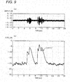
- FIG. 9 shows the waveform of the sound output from the first directivity forming section 1103 and the level Lx1(t) obtained when the first level calculation section 103 performed calculation.
- the calculated level Lx1(t) is an example obtained by the first level calculation section 103 in the case that the time constant in Mathematical expression (2) described above is 100 [ms] and that the time constant in Mathematical expression (3) described above is 400 [ms].
- FIG. 9(a) is a view showing the time change in the waveform of the sound output from the first directivity forming section 1103, and FIG. 9(b) is a view showing the time change in the level calculated by the first level calculation section 103.
- the vertical axis represents amplitude
- the horizontal axis represents time [sec].
- the vertical axis represents level
- the horizontal axis represents time [sec].
- the second level calculation section 104 obtains the sound signal x2(t) output from the second directivity forming section 1104 and calculates the level Lx2(t) of the obtained sound signal x2(t).
- the second level calculation section 104 outputs the calculated level Lx2(t) of the sound signal x2(t) to the utterer distance determination section 105.
- the calculation expression of the level Lx2(t) calculated by the second level calculation section 104 is the same as Mathematical expression (1) by which the level Lx1(t) is calculated.
- FIG. 10 shows the waveform of the sound output from the second directivity forming section 1104 and the level Lx2(t) obtained when calculation is performed by the second level calculation section 104.
- the calculated level Lx2(t) is an example obtained by the second level calculation section 104 in the case that the time constant in Mathematical expression (2) described above is 100 [ms] and that the time constant in Mathematical expression (3) described above is 400 [ms].
- FIG. 10(a) is a view showing the time change in the waveform of the sound output from the second directivity forming section 1104. Furthermore, FIG. 10(b) is a view showing the time change in the level calculated by the second level calculation section 104.
- the vertical axis represents amplitude
- the horizontal axis represents time [sec].
- the vertical axis represents level
- the horizontal axis represents time [sec].
- the utterer distance determination section 105 obtains the level Lx1(t) of the sound signal x1(t) calculated by the first level calculation section 103 and the level Lx2(t) of the sound signal x2(t) calculated by the second level calculation section 103. On the basis of these obtained level Lx1(t) and level Lx2(t), the utterer distance determination section 105 determines whether the utterer is close to the user. The utterer distance determination section 105 outputs distance determination result information serving as the result of the determination to the gain derivation section 106.
- the utterer distance determination section 105 determines whether the utterer is close to the user.
- the distance indicating that the utterer is close to the user corresponds to a distance of 2 [m] or less between the utterer and the user.
- the distance indicating that the utterer is close to the user is not limited to the distance of 2 [m] or less.
- the utterer distance determination section 105 determines that the utterer is close to the user.
- the first threshold value ⁇ 1 is 12 [dB] for example.
- the utterer distance determination section 105 determines that the utterer is far away from the user.
- the second threshold value ⁇ 2 is 8 [dB] for example. Furthermore, in the case that the level difference ⁇ Lx(t) is equal to or more than the second threshold value ⁇ 2 and less than the first threshold value ⁇ 1, the utterer distance determination section 105 determines that the utterer is slightly away from the user.
- FIG. 11 is a graph showing the relationship between the level difference ⁇ Lx(t) calculated by the above-mentioned method and the distance between the user and the utterer by using data picked up by the actual two omnidirectional microphones. According to FIG. 11 , it is possible to confirm that the level difference ⁇ Lx(t) lowers as the utterer becomes far away from the user.
- the utterer distance determination section 105 outputs the distance determination result information "1" indicating that the utterer is close to the user to the gain derivation section 106.
- the distance determination result information "1" represents that the direct sound picked up by the first directivity forming section 1103 is abundant and that the reverberant sound picked up by the second directivity forming section 1104 is scarce.
- the utterer distance determination section 105 outputs the distance determination result information "-1" indicating that the utterer is far away from the user.
- the distance determination result information "-1" represents that the direct sound picked up by the first directivity forming section 1103 is scarce and that the reverberant sound picked up by the second directivity forming section 1104 is abundant.
- the utterer distance determination section 105 outputs the distance determination result information "0" indicating that the utterer is slightly away from the user.
- Determining the distance of the utterer on the basis of only the magnitude of the level Lx1(t) calculated by the first level calculation section 103 is not efficient in the accuracy of the determination, as in the first embodiment. Due to the characteristics of the first directivity forming section 1103, when only the magnitude of the level Lx1(t) is used, it is difficult to determine the difference between a case in which a person far away from the user speaks at high volume and a case in which a person close to the user speaks at normal volume.
- the characteristics of the first and second directivity forming sections 1103 and 1104 are as described next.
- the sound signal x1(t) output from the first directivity forming section 1103 is relatively larger than the sound signal x2(t) output from the second directivity forming section 1104.
- the sound signal x1(t) output from the first directivity forming section 1103 is almost equal to the sound signal x2(t) output from the second directivity forming section 1104.
- this tendency becomes significant.
- the utterer distance determination section 105 does not determine whether the utterer is close to or far away from the user on the basis of only the magnitude of the level Lx1(t) calculated by the first level calculation section 103. Hence, the utterer distance determination section 105 determines the distance of the utterer on the basis of the difference between the level Lx1(t) of the sound signal x1(t) in which the direct sound is mainly picked up and the level Lx2(t) of the sound signal x2(t) in which the reverberant sound is mainly picked up.
- the gain derivation section 106 derives the gain ⁇ (t) corresponding to the sound signal x1(t) output from the first directivity forming section 1103 on the basis of the distance determination result information output from the utterer distance determination section 105.
- the gain derivation section 106 outputs the derived gain ⁇ (t) to the level control section 107.
- the gain ⁇ (t) is determined on the basis of the distance determination result information or the level difference ⁇ Lx(t).
- the relationship between the level difference ⁇ Lx(t) calculated by the utterer distance determination section 105 and the gain ⁇ (t) is the same as the relationship shown in FIG. 4 in the first embodiment.
- the gain ⁇ 1 is given as the gain ⁇ (t) corresponding to the sound signal x1(t). For example, when "2.0" is set as the gain ⁇ 1, the sound signal x1(t) is relatively emphasized.
- the gain ⁇ 2 is given as the gain ⁇ (t) corresponding to the sound signal x1(t).
- the gain ⁇ 2 is relatively attenuated.
- the sound signal x1(t) is not particularly emphasized or attenuated; hence, "1.0" is given as the gain ⁇ (t).
- the value derived as the gain ⁇ (t) in the above description is herein given as the instantaneous gain a'(t) to reduce the distortion that is generated in the sound signal x1(t) when the gain ⁇ (t) changes rapidly.
- the gain derivation section 106 calculates the gain ⁇ (t) according to Mathematical expression (4) described above.
- T ⁇ represents a time constant, has a value in the range of 0 ⁇ T ⁇ ⁇ 1 and has been determined in advance.
- the level control section 107 obtains the gain ⁇ (t) derived according to Mathematical expression (4) described above by the gain derivation section 106 and the sound signal x1(t) output from the first directivity forming section 1103.
- the level control section 107 generates an output signal y(t) that is obtained by multiplying the gain ⁇ (t) derived by the gain derivation section 106 to the sound signal x1(t) output from the first directivity forming section 1103.
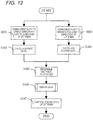
- FIG. 12 is a flowchart illustrating the operation of the sound processing apparatus 11 according to the second embodiment.
- the first directivity forming section 1103 forms the directivity regarding the direct sound component from the utterer with respect to the sound signals respectively output from the microphone array 1102 of the directional sound pickup section 1101 (at S651).
- the first directivity forming section 1103 outputs a sound signal, the directivity of which has been formed, to each of the first level calculation section 103 and the level control section 107.
- the second directivity forming section 1104 forms the directivity regarding the reverberant sound component from the utterer with respect to the sound signals respectively output from the microphone array 1102 of the directional sound pickup section 1101 (at S652).
- the second directivity forming section 1104 outputs a sound signal, the directivity of which has been formed, to the second level calculation section 104.
- the first level calculation section 103 obtains the sound signal x1(t) output from the first directivity forming section 1103 and calculates the level Lx1(t) of the obtained sound signal x1(t) (at S103).
- the second level calculation section 104 obtains the sound signal x2(t) output from the second directivity forming section 1104 and calculates the level Lx2(t) of the obtained sound signal x2 (at S104).
- the first level calculation section 103 outputs the calculated level Lx1(t) to the utterer distance determination section 105. Furthermore, the second level calculation section 104 outputs the calculated level Lx2(t) to the utterer distance determination section 105.
- the utterer distance determination section 105 obtains the level Lx1(t) calculated by the first level calculation section 103 and the level Lx2(t) calculated by the second level calculation section 104.
- the utterer distance determination section 105 determines whether the utterer is close to the user on the basis of the level difference ⁇ Lx(t) between the level Lx1(t) and the level Lx2(t) obtained as described above (at S105).
- the utterer distance determination section 105 outputs the distance determination result information serving as the result of the determination to the gain derivation section 106.
- the gain derivation section 106 obtains the distance determination result information output from the utterer distance determination section 105.
- the gain derivation section 106 derives the gain ⁇ (t) corresponding to the sound signal x1(t) output from the first directivity forming section 1103 on the basis of the distance determination result information output from the utterer distance determination section 105 (at S106).
- the details of the derivation of the gain ⁇ (t) have been described referring to FIG. 6 in the first embodiment and thus the descriptions thereof are omitted.
- the gain derivation section 106 outputs the derived gain ⁇ (t) to the level control section 107.
- the level control section 107 obtains the gain ⁇ (t) derived from the gain derivation section 106 and the sound signal x1(t) output from the first directivity forming section 1103.
- the level control section 107 generates the output signal y(t) that is obtained by multiplying the gain ⁇ (t) derived by the gain derivation section 106 to the sound signal x1(t) output from the first directivity forming section 1103 (at S107).
- sound pickup is performed by the microphone array in which a plurality of omnidirectional microphones are disposed at a distance of approximately several [mm] to several [cm] therebetween.
- the apparatus it is determined whether the utterer is close to or far away from the user according to the magnitude of the level difference ⁇ Lx(t) between the sound signals x1(t) and x2(t), the directivities of which have been formed by the first and second directivity forming sections.
- the gain calculated according to the result of the determination is multiplied to the sound signal output to the first directivity forming section for picking up the direct sound of the utterer, and the level is controlled.
- the sound of the utterer close to the user such as the conversational partner thereof, is emphasized; conversely, the sound of the utterer far away from the user is attenuated or suppressed.
- the sound of the conversational partner close to the user can be emphasized so as to be heard clearly and efficiently, regardless of the distance between the microphones.
- sharp directivity can be formed in the direction of the utterer by increasing the number of the omnidirectional microphones constituting the microphone array, whereby the distance of the utterer can be determined highly accurately.
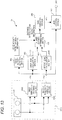
- FIG. 13 is a block diagram showing an internal configuration of a sound processing apparatus 12 according to a third embodiment.
- the sound processing apparatus 12 according to the third embodiment is different from the sound processing apparatus 11 according to the second embodiment in that the apparatus further has a component, that is, a voice activity detection section 501 as shown in FIG. 13 .
- a component that is, a voice activity detection section 501 as shown in FIG. 13 .
- FIG. 13 the same components as those shown in FIG. 7 are designated by the same reference codes and the descriptions of the components are omitted.
- the voice activity detection section 501 obtains the sound signal x1(t) output from the first directivity forming section 1103. By using the sound signal x1(t) output from the first directivity forming section 1103, the voice activity detection section 501 detects an interval in which the utterer, excluding the user of the sound processing apparatus 12, produces sound. The voice activity detection section 501 outputs this detected voice activity detection result information to the utterer distance determination section 105.
- FIG. 14 is a block diagram showing an example of an internal configuration of the voice activity detection section 501.
- the voice activity detection section 501 has a third level calculation section 601, an estimated noise level calculation section 602, a level comparison section 603, and a voice activity determination section 604.
- the third level calculation section 601 calculates the level Lx3(t) of the sound signal x1(t) output from the first directivity forming section 1103 according to Mathematical expression (1) described above.
- the level Lx1(t) of the sound signal x1(t) calculated by the first level calculation section 103 instead of the level Lx3(t), may be input to each of the estimated noise level calculation section 602 and the level comparison section 603.
- the third level calculation section 601 outputs the calculated level Lx3(t) to each of the estimated noise level calculation section 602 and the level comparison section 603.
- the estimated noise level calculation section 602 obtains the level Lx3(t) output from the third level calculation section 601.
- the estimated noise level calculation section 602 calculates the estimated noise level Nx(t) [dB] for the obtained level Lx3(t).
- T N is a time constant, has a value in the range of 0 ⁇ T N ⁇ 1 and has been determined in advance.
- Lx3(t)>Nx(t-1) a large time constant is used as the time constant T N so that the estimated noise level Nx(t) does not rise in the speech interval.
- the estimated noise level calculation section 602 outputs the calculated estimated noise level Nx(t) to the level comparison section 603.
- the level comparison section 603 obtains each of the estimated noise level Nx(t) calculated by the estimated noise level calculation section 602 and the level Lx3(t) calculated by the third level calculation section 601. The level comparison section 603 compares the level Lx3(t) with the noise level Nx(t) and outputs the comparison result information obtained by the comparison to the voice activity determination section 604.
- the voice activity determination section 604 obtains the comparison result information output from the level comparison section 603. On the basis of the obtained comparison result information, the voice activity determination section 604 determines an interval in which the utterer produces sound for the sound signal x1(t) output from the first directivity forming section 1103. The voice activity determination section 604 outputs the voice activity detection result information serving as the voice activity detection result having been determined as the speech interval to the utterer distance determination section 105.
- the level comparison section 603 In the comparison between the level Lx3(t) and the estimated noise level Nx(t), the level comparison section 603 outputs an interval in which the difference between the level Lx3(t) and the estimated noise level Nx(t) is equal to or more than a third threshold value ⁇ N as a "speech interval" to the voice activity determination section 604.
- the third threshold value ⁇ N is 6 [dB] for example. Furthermore, the level comparison section 603 compares the level Lx3(t) with the estimated noise level Nx(t) and outputs an interval in which the difference therebetween is less than the third threshold value ⁇ N as a "no-speech interval" to the voice activity determination section 604.
- FIG. 15 is a view showing the time change in the waveform of the sound signal output from the first directivity forming section 1103, a view showing the time change in the detection result obtained by the voice activity determination section 604, and a view showing the time change in the result of the comparison between the level calculated by the third level calculation section 601 and the estimated noise level.
- FIG. 15(a) is a view showing the time change in the waveform of the sound signal x1(t) output from the first directivity forming section 1103.
- the vertical axis represents amplitude
- the horizontal axis represents time [sec].
- FIG. 15(b) is a view showing the time change in the voice activity detection result detected by the voice activity determination section 604.
- the vertical axis represents voice activity detection result
- the horizontal axis represents time [sec].
- FIG. 15(c) is a view showing the comparison between the level Lx3(t) and the estimated noise level Nx(t) with respect to the waveform of the sound signal x1(t) output from the first directivity forming section 1103.
- the vertical axis represents level
- the horizontal axis represents time [sec].
- FIG. 15(c) an example is shown in which the time constant in the case of Lx3(t) ⁇ Nx(t-1) is 1 [sec] and the time constant in the case of Lx3(t)>Nx(t - 1) is 120 [sec].
- FIG. 15(b) and FIG. 15(c) show the level Lx3(t), the noise level Nx(t), (Nx(t) + ⁇ N) in the case that the third threshold value ⁇ N is 6 [dB], and the sound detection result.
- the utterer distance determination section 105 obtains the voice activity detection result information output from the voice activity determination section 604 of the voice activity detection section 501. On the basis of the obtained voice activity detection result information, the utterer distance determination section 105 determines whether the utterer is close to the user only in the voice activity detected by the voice activity detection section 501. The utterer distance determination section 105 outputs the distance determination result information obtained by the determination to the gain derivation section 106.
- FIG. 16 is a flowchart illustrating the operation of the sound processing apparatus 12 according to the third embodiment.
- the description of the same operation as the operation of the sound processing apparatus 11 according to the second embodiment shown in FIG. 12 is omitted, and the processes relating to the above-mentioned components will mainly be described.
- the first directivity forming section 1103 outputs the sound signal x1(t) formed at step S651 to each of the voice activity detection section 501 and the level control section 107.
- the voice activity detection section 501 obtains the sound signal x1(t) output from the first directivity forming section 1103.
- the voice activity detection section 501 detects an interval in which the utterer produces sound using the sound signal x1(t) output from the first directivity forming section 1103 (at S321).
- the voice activity detection section 501 outputs the detected voice activity detection result information to the utterer distance determination section 105.
- the third level calculation section 601 calculates the level Lx3(t) of the sound signal x1(t) output from the first directivity forming section 1103 according to Mathematical expression (1) described above.
- the third level calculation section 601 outputs the calculated level Lx3(t) to each of the estimated noise level calculation section 602 and the level comparison section 603.
- the estimated noise level calculation section 602 obtains the level Lx3(t) output from the third level calculation section 601.
- the estimated noise level calculation section 602 calculates the estimated noise level Nx(t) corresponding to the obtained level Lx3(t).
- the estimated noise level calculation section 602 outputs the calculated estimated noise level Nx(t) to the level comparison section 603.
- the level comparison section 603 obtains each of the estimated noise level Nx(t) calculated by the estimated noise level calculation section 602 and the level Lx3(t) calculated by the third level calculation section 601. The level comparison section 603 compares the level Lx3(t) with the noise level Nx(t) and outputs the comparison result information obtained by the comparison to the voice activity determination section 604.
- the voice activity determination section 604 obtains the comparison result information output from the level comparison section 603. On the basis of the obtained comparison result information, the voice activity determination section 604 determines an interval in which the utterer produces sound for the sound signal x1(t) output from the first directivity forming section 1103. The voice activity determination section 604 outputs the voice activity detection result information serving as the voice activity detection result having been determined as the voice activity to the utterer distance determination section 105.
- the utterer distance determination section 105 obtains the voice activity detection result information output from the voice activity determination section 604 of the voice activity detection section 501.
- the utterer distance determination section 105 determines whether the utterer is close to the user only in the voice activity detected by the voice activity detection section 501 on the basis of the obtained voice activity detection result information (at S105).
- the details of the following processes are the same as those in the second embodiment (refer to FIG. 12 ) and the descriptions thereof are omitted.
- the voice activity of the sound signal formed by the first directivity forming section is detected by the voice activity detection section 501 added to the internal configuration of the sound processing apparatus according to the second embodiment. Only in the detected speech interval, it is determined whether the utterer is close to or far away from the user. The gain calculated according to the result of the determination is multiplied to the sound signal output to the first directivity forming section for picking up the direct sound of the utterer, and the level is controlled.
- the sound of the utterer close to the user such as the conversational partner thereof, is emphasized; conversely, the sound of the utterer far away from the user is attenuated or suppressed.
- the sound of the conversational partner close to the user is emphasized so as to be heard clearly and efficiently, regardless of the distance between the microphones.
- the distance to the utterer is determined only in the speech interval of the sound signal x1(t) output from the first directivity forming section, the distance to the utterer can be determined highly accurately.
- FIG. 17 is a block diagram showing an internal configuration of a sound processing apparatus 13 according to a fourth embodiment.
- the fourth processing apparatus 13 according to the fourth embodiment is different from the sound processing apparatus 12 according to the third embodiment in that the apparatus further has components, that is, a self-utterance sound determination section 801 and a distance determination threshold value setting section 802 as shown in FIG. 17 .
- self-utterance sound represents the sound produced by the user wearing a hearing aid equipped with the sound processing apparatus 13 according to the fourth embodiment.
- the voice activity detection section 501 obtains the sound signal x1(t) output from the first directivity forming section 1103. By using the sound signal x1(t) output from the first directivity forming section 1103, the voice activity detection section 501 detects an interval in which the user of the sound processing apparatus 13 or the utterer produces sound.
- the voice activity detection section 501 outputs this detected voice activity detection result information to each of the utterer distance determination section 105 and the self-utterance sound determination section 801.
- the specific components of the voice activity detection section 501 are the same as the components shown in FIG. 14 .
- the self-utterance sound determination section 801 obtains the voice activity detection result information output from the voice activity detection section 501.
- the self-utterance sound determination section 801 determines whether the sound detected by the voice activity detection section 501 is self-utterance sound by using the absolute sound pressure level of the level Lx3(t) in the voice activity based on the obtained voice activity detection result information.
- the self-utterance sound determination section 801 determines that the sound corresponding to the level Lx3(t) as self-utterance sound.
- the fourth threshold value ⁇ 4 is 74 [dB(SPL)] for example.
- the self-utterance sound determination section 801 outputs the self-utterance sound determination result information corresponding to the result of the determination to each of the distance determination threshold value setting section 802 and the utterer distance determination section 105.
- the self-utterance sound determination section 801 outputs "0" or "-1" as the self-utterance sound determination result information.
- the self-utterance sound itself should not be level-controlled by the level control section 107 from the viewpoint of protecting the ear of the user.
- the distance determination threshold value setting section 802 obtains the self-utterance sound determination information output from the self-utterance sound determination section 801.
- the distance determination threshold value setting section 802 eliminates the direct sound component contained in the sound signal x2(t) by using the sound signals x1(t) and x2(t) in the voice activity having been determined as self-utterance sound by the self-utterance sound determination section 801.
- the distance determination threshold value setting section 802 calculates the reverberation level contained in the sound signal x2(t).
- the distance determination threshold value setting section 802 sets the first threshold value ⁇ 1 and the second threshold value ⁇ 2 according to the calculated reverberation level.
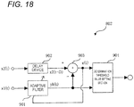
- FIG. 18 shows an example of an internal configuration of the distance determination threshold value setting section 802 equipped with an adaptive filter.
- FIG. 18 is a block diagram showing the internal configuration of the distance determination threshold value setting section 802.
- the distance determination threshold value setting section 802 is formed of an adaptive filter 901, a delay device 902, a difference signal calculation section 903, and a determination threshold value setting section 904.
- the adaptive filter 901 convolutes the coefficient of the adaptive filter 901 with the sound signal x1(t) output from the first directivity forming section 1103. Next, the adaptive filter 901 outputs the convoluted sound signal yh(t) to each of the difference signal calculation section 903 and the determination threshold value setting section 904.
- the delay device 902 delays the sound signal x2(t) output from the second directivity forming section 1104 by a predetermined amount and outputs the delayed sound signal x2(t - D) to the difference signal calculation section 903.
- the parameter D represents the number of samples delayed by the delay device 902.
- the difference signal calculation section 903 obtains the sound signal yh(t) output from the adaptive filter 901 and the sound signal x2(t - D) delayed by the delay device 902. The difference signal calculation section 903 calculates the difference signal e(t) between the sound signal x2(t - D) and the sound signal yh(t).
- the difference signal calculation section 903 outputs the calculated difference signal e(t) to the determination threshold value setting section 904.
- the adaptive filter 901 renews the coefficient of the filter by using the difference signal e(t) calculated by the difference signal calculation section 903.
- the coefficient of the filter is adjusted so that the direct sound component contained in the sound signal x2(t) output from the second directivity forming section 1104 is eliminated.
- the tap length of the filter 901 is made relatively short since only the direct sound component of the sound signal x2(t) output from the second directivity forming section 1104 is eliminated and the reverberant sound component of the sound signal x2(t) is output as the difference signal.
- the tap length of the filter 901 is a length corresponding to approximately several [msec] to several ten [msec].
- the delay device 902 for delaying the sound signal x2(t) output from the second directivity forming section 1104 is inserted to satisfy the causality with the first directivity forming section 1103. This is because a predetermined amount of delay occurs inevitably when the sound signal x1(t) output from the first directivity forming section 1103 passes through the adaptive filter 901.
- the number of samples to be delayed is set to a value approximately half of the tap length of the adaptive filter 901.
- the determination threshold value setting section 904 obtains each of the difference signal e(t) output from the difference signal calculation section 903 and the sound signal yh(t) output from the adaptive filter 901.
- the determination threshold value setting section 904 calculates the level Le(t) by using the obtained difference signal e(t) and the obtained sound signal yh(t) and sets the first threshold value ⁇ 1 and the second threshold value ⁇ 2.
- the level Le(t) [dB] is calculated according to Mathematical expression (6).
- the parameter L is the number of samples for level calculation.
- Mathematical expression (6) in order that the dependence to the absolute level of the difference signal e(t) is reduced, normalization is performed at the level of the sound signal yh(t) that serves as the estimated signal of the direct sound and is output from the adaptive filter 901.
- the value of the level Le(t) becomes large in the case that the reverberant sound component is abundant, and the value becomes small in the case that the reverberant sound component is scarce.
- the numerator in Mathematical expression (6) becomes small, whereby Le(t) becomes a value close to - ⁇ [dB].
- the denominator and the numerator in Mathematical expression (6) have the same level, whereby Le(t) becomes a value close to 0 [dB].
- the level Le(t) is larger than a predetermined value
- reverberant sound is picked up abundantly by the second directivity forming section 1104 even in the case that the utterer is close to the user.
- the predetermined value is -10 [dB] for example.
- the first threshold value ⁇ 1 and the second threshold value ⁇ 2 are respectively set to small values.
- the level Le(t) is smaller than a predetermined value, reverberant sound is not picked up abundantly by the second directivity forming section 1104.
- the predetermined value is -10 [dB] for example.
- the first threshold value ⁇ 1 and the second threshold value ⁇ 2 are respectively set to large values.
- the voice activity detection result information from the voice activity detection section 501, the self-utterance sound determination result information from the self-utterance sound determination section 801, and the first and second threshold values ⁇ 1 and ⁇ 2 having been set by the distance determination threshold value setting section 802 are input.
- the utterer distance determination section 105 determines whether the utterer is close to the user on the basis of the voice activity detection result information having been input, the self-utterance sound determination result information having been input and the first and second threshold values ⁇ 1 and ⁇ 2 having been set.
- the utterer distance determination section 105 outputs the distance determination result information obtained by the determination to the gain derivation section 106.
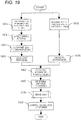
- FIG. 19 is a flowchart illustrating the operation of the sound processing apparatus 13 according to the fourth embodiment.
- the description of the same operation as the operation of the sound processing apparatus 13 according to the third embodiment shown in FIG. 16 is omitted, and the processes relating to the above-mentioned components will mainly be described.
- the voice activity detection section 501 outputs the detected voice activity detection result information to each of the utterer distance determination section 105 and the self-utterance sound determination section 801.
- the self-utterance sound determination section 801 obtains the voice activity detection result information output from the voice activity detection section 501.
- the self-utterance sound determination section 801 determines whether the sound detected by the voice activity detection section 501 is self-utterance sound by using the absolute sound pressure level of the level Lx3(t) in the voice activity based on the obtained voice activity detection result information (at S431).
- the self-utterance sound determination section 801 outputs the self-utterance sound determination result information corresponding to the result of the determination to each of the distance determination threshold value setting section 802 and the utterer distance determination section 105.
- the distance determination threshold value setting section 802 obtains the self-utterance sound determination result information output from the self-utterance sound determination section 801.
- the distance determination threshold value setting section 802 calculates the reverberation level contained in the sound signal x2(t) by using the sound signals x1(t) and x2(t) in the speech interval having determined as self-utterance sound by the self-utterance sound determination section 801.
- the distance determination threshold value setting section 802 sets the first threshold value ⁇ 1 and the second threshold value ⁇ 2 according to the calculated reverberation level (at S432).
- the voice activity detection result information from the voice activity detection section 501, the self-utterance sound determination result information from the self-utterance sound determination section 801, and the first and second threshold values ⁇ 1 and ⁇ 2 having been set by the distance determination threshold value setting section 802 are input.
- the utterer distance determination section 105 determines whether the utterer is close to the user on the basis of the voice activity detection result information having been input, the self-utterance sound determination result information having been input and the first and second threshold values ⁇ 1 and ⁇ 2 having been set (at S105).
- the utterer distance determination section 105 outputs the distance determination result information obtained by the determination to the gain derivation section 106.
- the details of the following processes are the same as those in the first embodiment (refer to FIG. 5 ) and the descriptions thereof are omitted.
- a determination as to whether self-utterance sound is contained in the sound signal x1(t) picked up by the first directivity forming section is made by the self-utterance sound determination section added to the internal configuration of the sound processing apparatus according to the third embodiment.
- the reverberation levels contained in the sound signals respectively picked up by the second directivity forming section are calculated in the speech interval having been determined as self-utterance sound by the distance determination threshold value setting section added to the internal configuration of the sound processing apparatus according to the third embodiment.
- the first threshold value ⁇ 1 and the second threshold value ⁇ 2 are set according to the calculated reverberation levels by the distance determination threshold value setting section.
- the utterer on the basis of the first threshold value ⁇ 1 and the second threshold value ⁇ 2 having been set and the voice activity detection result information and the self-utterance sound determination result information, it is determined whether the utterer is close to or far away from the user.
- the gain calculated according to the result of the determination is multiplied to the sound signal output to the first directivity forming section 1103 for picking up the direct sound of the utterer, and the level is controlled.
- the sound of the utterer close to the user such as the conversational partner thereof, is emphasized; conversely, the sound of the utterer far away from the user is attenuated or suppressed.
- the sound of the conversational partner close to the user is emphasized so as to be heard clearly and efficiently, regardless of the distance between the microphones.
- the distance of the utterer is determined only in the speech interval of the sound signal x1(t) output from the first directivity forming section 1103, the distance of the utterer can be determined highly accurately.
- the threshold values for determining the distance can be set dynamically according to the reverberation levels. Hence, in this embodiment, the distance between the user and the utterer can be determined highly accurately.
- FIG. 20 is a block diagram showing an internal configuration of a sound processing apparatus 14 according to a fifth embodiment.
- the sound processing apparatus 14 according to the fifth embodiment is different from the sound processing apparatus 12 according to the third embodiment in that the apparatus further has components, that is, the self-utterance sound determination section 801 and a conversational partner determination section 1001 as shown in FIG. 20 .
- the same components as those shown in FIG. 7 are designated by the same reference codes and the descriptions thereof are omitted.
- the self-utterance sound determination section 801 obtains the voice activity detection result information output from the voice activity detection section 501.
- the self-utterance sound determination section 801 determines whether the sound detected by the voice activity detection section 501 is self-utterance sound by using the absolute sound pressure level of the level Lx3(t) in the speech interval based on the obtained voice activity detection result information.
- the mouth of the user serving as the sound source of the self-utterance sound is close to the user's ear in which the first directivity forming section 1103 is disposed; hence, the absolute sound pressure level of the self-utterance sound picked up by the first directivity forming section 1103 is high.
- the level Lx3(t) is equal to or more than the fourth threshold value ⁇ 4, the sound corresponding to the level Lx3(t) is determined as self-utterance sound.
- the fourth threshold value ⁇ 4 is 74 [dB(SPL)] for example.
- the self-utterance sound determination section 801 outputs the self-utterance sound determination result information corresponding to the result of the determination to the conversational partner determination section 1001. Furthermore, the self-utterance sound determination section 801 may output the self-utterance sound determination result information to each of the utterer distance determination section 105 and the conversational partner determination section 1001.
- the utterer distance determination section 105 determines whether the utterer is close to the user on the basis of the voice activity detection result information from the voice activity detection section 501. Furthermore, the utterer distance determination section 105 may obtain the self-utterance sound determination result information output from the self-utterance sound determination section 801.
- the utterer distance determination section 105 determines the distance to the utterer in the interval detected as the speech interval excluding the speech interval having been determined as self-utterance sound.
- the utterer distance determination section 105 outputs the determined distance determination result information to the conversational partner determination section 1001 on the basis of the voice activity detection result information.
- the utterer distance determination section 105 may output the distance determination result information obtained by the determination to the conversational partner determination section 1001 on the basis of the voice activity detection result information and the self-utterance sound determination result information.
- the conversational partner determination section 1001 obtains the self-utterance sound determination result information from the self-utterance sound determination section 801 and the distance determination result information from the utterer distance determination section 105.
- the conversational partner determination section 1001 determines whether the utterer is the conversational partner of the user by using the sound of the utterer close to the user and the self-utterance sound determined by the self-utterance sound determination section 801.
- the case in which the utterer distance determination section 105 determines that the utterer is close to the user is the case in which the distance determination result information indicates "1".
- the conversational partner determination section 1001 In the case that it is determined that the utterer is the conversational partner of the user, the conversational partner determination section 1001 outputs the conversational partner determination information "1" to the gain derivation section 106. On the other hand, in the case that it is determined that the utterer is not the conversational partner of the user, the conversational partner determination section 1001 outputs the conversational partner determination information "0" or "-1" to the gain derivation section 106.
- FIG. 21 is a view showing an example in which the distance determination result information and the self-utterance sound determination result information are represented in the same time axis.
- FIG. 22 is a view showing another example in which the distance determination result information and the self-utterance sound determination result information are represented in the same time axis.
- the distance determination result information and the self-utterance sound determination result information shown in FIGS. 21 and 22 are referred to by the conversational partner determination section 1001.
- FIG. 21 is a view at the time when the self-utterance sound determination result information is not output to the utterer distance determination section 105; in this case, the self-utterance sound determination result information is output to the conversational partner determination section 1001.
- the self-utterance sound determination result information is "1"
- the distance determination result information also becomes “1” as shown in FIG. 21 .
- the conversational partner determination section 1001 treats the distance determination result information as "0". In the case that the state in which the distance determination result information is "1" and the state in which the self-utterance sound determination result information is "1" occur alternately and almost continuously in terms of time, the conversational partner determination section 1001 determines that the utterer is the conversational partner of the user.
- FIG. 22 is a view at the time when the self-utterance sound determination result information is output to the utterer distance determination section 105.
- the conversational partner determination section 1001 determines that the utterer is the conversational partner of the user.
- the gain derivation section 106 derives the gain ⁇ (t) by using the conversational partner determination result information from the conversational partner determination section 1001. More specifically, in the case that the conversational partner determination result information is "1", since the utterer is determined as the conversational partner of the user, the gain derivation section 106 sets the installation gain a'(t) to "2.0".
- the gain derivation section sets the installation gain a'(t) to "0.5” or "1.0".
- the gain may be set to "0.5” or "1.0".
- the gain derivation section 106 derives the gain ⁇ (t) according to Mathematical expression (4) described above by using the derived installation gain a'(t) and outputs the derived gain ⁇ (t) to the level control section 107.
- FIG. 23 is a flowchart illustrating the operation of the sound processing apparatus 14 according to the fifth embodiment.
- the description of the same operation as the operation of the sound processing apparatus 12 according to the third embodiment shown in FIG. 16 is omitted, and the processes relating to the above-mentioned components will mainly be described.
- the voice activity detection section 501 outputs the detected voice activity detection result information to each of the utterer distance determination section 105 and the self-utterance sound determination section 801.
- the self-utterance sound determination section 801 obtains the voice activity detection result information output from the voice activity detection section 501.
- the self-utterance sound determination section 801 determines whether the sound detected by the voice activity detection section 501 is self-utterance sound by using the absolute sound pressure level of the level Lx3(t) in the speech interval based on the voice activity detection result information (at S431).
- the self-utterance sound determination section 801 outputs the self-utterance sound determination result information corresponding to the result of the determination to the conversational partner determination section 1001. In addition, it may be possible that the self-utterance sound determination section 801 outputs the self-utterance sound determination result information to the conversational partner determination section 1001 and the utterer distance determination section 105.
- the utterer distance determination section 105 determines whether the utterer is close to the user on the basis of the voice activity detection result information from the voice activity detection section 501 (at S105). In the case that it is determined that the utterer is close to the user by the utterer distance determination section 105 (YES at S541), the conversational partner determination section 1001 determines whether the utterer is the conversational partner of the user (at S542). More specifically, the conversational partner determination section 1001 determines whether the utterer is the conversational partner of the user by using the sound of the utterer close to the user and the self-utterance sound having been determined by the self-utterance sound determination section 801.
- the gain deriving process using the gain derivation section 106 is performed (at S106).
- the gain derivation section 106 derives the gain ⁇ (t) by using the conversational partner determination result information from the conversational partner determination section 1001 (at S106).
- the details of the following processes are the same as those in the first embodiment (refer to FIG. 5 ) and the descriptions thereof are omitted.
- a determination as to whether self-utterance sound is contained in the sound signal x1(t) picked up by the first directivity forming section is made by the self-utterance sound determination section added to the internal configuration of the sound processing apparatus according to the third embodiment.
- the conversational partner determination section in the speech interval in which it has been determined that the utterer is close to the user by the conversational partner determination section, it is determined whether the utterer is the conversational partner of the user on the basis of the time-wise chronological order of the self-utterance sound determination result information and the distance determination result information.
- the gain calculated on the basis of the conversational partner determination result information obtained by the determination is multiplied to the sound signal output to the first directivity forming section for picking up the direct sound of the utterer, and the level is controlled.
- the sound of the utterer close to the user such as the conversational partner thereof, is emphasized; conversely, the sound of the utterer far away from the user is attenuated or suppressed.
- the sound of the conversational partner close to the user is emphasized so as to be heard clearly and efficiently, regardless of the distance between the microphones.
- the distance of the utterer is determined only in the speech interval of the sound signal x1(t) output from the first directivity forming section, the distance of the utterer can be determined highly accurately.
- the sound of the utterer can be emphasized only in the case that the utterer close to the user is the conversational partner, and the sound of only the conversational partner of the user can be heard clearly.
- FIG. 24 is a block diagram showing an internal configuration of a sound processing apparatus 15 according to a sixth embodiment.
- the sound processing apparatus 15 according to the sixth embodiment is an apparatus in which the sound processing apparatus 11 according to the second embodiment is applied to a hearing aid.
- the apparatus is different from the sound processing apparatus 11 according to the second embodiment in that the gain derivation section 106 and the level control section 107 shown in FIG. 7 are integrated into a nonlinear amplification section 3101 and that the apparatus is further equipped with a speaker 3102 as a sound output section as shown in FIG. 24 .
- the same components as those shown in FIG. 7 are designated by the same reference codes and the descriptions of the components are omitted.
- the nonlinear amplification section 3101 obtains the sound signal x1(t) output from the first directivity forming section 1103 and the distance determination result information output from the utterer distance determination section 105. On the basis of the distance determination result information output from the utterer distance determination section 105, the nonlinear amplification section 3101 amplifies the sound signal x1(t) output from the first directivity forming section 1103 and outputs the signal to the speaker 3102.
- FIG. 25 is a block diagram showing an example of an internal configuration of the nonlinear amplification section 3101.
- the nonlinear amplification section 3101 has a band division section 3201, a plurality of band signal control sections (#1 to "N) 3202, and a band synthesis section 3203.
- the band division section 3201 divides the sound signal x1(t) from the first directivity forming section 1103 into N band frequency band signals x1n(t) using a filter or the like.
- a DFT (Discrete Fourier Transform) filter bank, a band pass filter, etc. is used as the filter.
- each of the band signal control sections (#1 to "N) 3202 sets a gain that is multiplied to each frequency band signal x1n(t). Next, each of the band signal control sections (#1 to #N) 3202 controls the level of each frequency band signal x1n(t) by using the set gain.
- FIG. 25 shows an internal configuration of the band signal control section (#n) 3202 in the frequency band #n among the band signal control sections (#1 to #N) 3202.
- the band signal control section (#n) 3202 has a band level calculation section 3202-1, a band gain setting section 3202-2, and a band gain control section 3202-3.
- the band signal control sections 3202 in the other frequency bands have similar internal configurations.
- the band level calculation section 3202-1 calculates the level Lx1n(t) [dB] of the frequency band signal x1n(t). The calculation is performed using a level calculation method, such as Mathematical expression (1) described above.
- the band gain setting section 3202-2 To the band gain setting section 3202-2, the band level Lx1n(t) calculated by the band level calculation section 3202-1 and the distance determination result information output from the utterer distance determination section 105 are input. Next, on the basis of the band level Lx1n(t) and the distance determination result information, the band gain setting section 3202-2 sets a band gain an(t) that is multiplied to the band signal x1n(t) serving as the control target of the band signal control section 3202.
- the band gain setting section 3202-2 sets the band gain an(t) for compensating for such aural characteristics of the user as shown in FIG.26 by using the band level Lx1n(t) of the signal.
- FIG. 26 is a view illustrating the input-output characteristics of the level for compensating for the aural characteristics of the user.
- the band gain setting section 3202-2 sets "1.0" as the band gain an(t) for the band signal x1n(t) serving as the control target.
- the band gain control section 3202-3 multiplies the band gain an(t) to the band signal x1n(t) serving as the control target, thereby calculating a band signal yn(t) after the control by the band signal control section 3202.
- the band synthesis section 3203 synthesizes the respective band signals yn(t) by using a method corresponding to the band division section 3201, thereby calculating a signal y(t) after the band synthesis.
- the speaker 3102 outputs the signal y(t) after the band synthesis in which the band gain has been set by the nonlinear amplification section 3101.
- FIG. 27 is a flowchart illustrating the operation of the sound processing apparatus 15 according to the sixth embodiment.
- the description of the same operation as the operation of the sound processing apparatus 11 according to the second embodiment shown in FIG. 12 is omitted, and the processes relating to the above-mentioned components will mainly be described.
- the nonlinear amplification section 3101 obtains the sound signal x1(t) output from the first directivity forming section 1103 and the distance determination result information output from the utterer distance determination section 105. Next, on the basis of the distance determination result information output from the utterer distance determination section 105, the nonlinear amplification section 3101 amplifies the sound signal x1(t) output from the first directivity forming section 1103 and outputs the signal to the speaker 3102 (at S3401).
- FIG. 28 is a flowchart illustrating the details of the operation of the nonlinear amplification section 3101.
- the band division section 3201 divides the sound signal x1(t) output from the first directivity forming section 1103 into N band frequency band signals x1n(t) (at S3501).
- the band level calculation section 3202-1 calculates the level Lx1n(t) of each respective frequency band signal x1n(t) (at S3502).
- the band gain setting section 3202-2 sets the band gain an(t) that is multiplied to the band signal x1n(t) (at S3503).
- FIG. 29 is a flowchart illustrating the details of the operation of the band gain setting section 3202-2.
- the band gain setting section 3202-2 sets the band gain an(t) for compensating for such aural characteristics of the user as shown in FIG. 26 by using the band level Lx1n(t) (at S3602).
- the band gain setting section 3202-2 sets "1.0" as the band gain an(t) for the band signal x1n(t) (at S3603).
- the band gain control section 3202-3 multiplies the band gain an(t) to the band signal x1n(t), thereby calculating the band signal yn(t) after the control by the band signal control section 3202 (at S3504).
- the band synthesis section 3203 synthesizes the respective band signals yn(t) by using the method corresponding to the band division section 3201, thereby calculating the signal y(t) after the band synthesis (at S3505).
- the speaker 3102 outputs the signal y(t) after the band synthesis in which the gain has been adjusted (at S3402).
- the gain derivation section 106 and the level control section 107 in the internal configuration of the sound processing apparatus 11 according to the second embodiment are integrated into the nonlinear amplification section 3101. Furthermore, the sound processing apparatus 15 according to the sixth embodiment is further equipped with a component, that is, the speaker 3102 in the sound output section; hence, only the sound of the conversational partner can be amplified, and only the sound of the conversational partner of the user can be heard clearly.
- the value of the above-mentioned installation gain a'(t) is specifically described as "2.0” or "0.5", the value is not limited to these values.
- the value of the installation gain a'(t) can also be set individually in advance according to, for example, the degree of hearing difficulty of the user who uses the apparatus as a hearing aid.
- the conversational partner determination section determines whether the utterer is the conversational partner of the user by using the sound of the utterer and the self-utterance sound determined by the self-utterance sound determination section.
- the conversational partner determination section 1001 recognizes the sound of the utterer and the sound of the self-utterance. At this time, in the case that the conversational partner determination section 1001 extracts predetermined keywords in the recognized sound and determines that keywords in the same field are used, it may be possible that the utterer is determined as the conversational partner of the user.
- the predetermined keywords are, for example, keywords, such as “airplane”, “car”, “Hokkaido” and “Kyushu”, these relating to the same field.
- the conversational partner determination section 1001 performs specific utterer recognition for au utterer close to the user.
- the person determined as the result of the recognition is a specific utter having been registered in advance or in the case that only one utterer is present around the user, the person is determined as the conversational partner of the user.
- the first level calculation process has been described so as to be performed after the voice activity detection process. However, it may be possible that the first level calculation process is performed before the voice activity detection process.
- the first level calculation process is performed after the voice activity detection process and the self-utterance sound determination process and before the distance determination threshold value setting process.
- the first level calculation process is performed before the sound detection process or the self-utterance sound determination process or after the distance determination threshold value setting.
- the second level calculation process is performed before the distance determination threshold value setting process. However, it may be possible that the second level calculation process is performed after the distance determination threshold value setting.
- the first level calculation process is performed after the voice activity detection process and the self-utterance sound determination process.
- the conditions for allowing the self-utterance sound determination process to be performed after the voice activity detection process have been satisfied, it may be possible that the first level calculation process is performed before the voice activity detection process or the self-utterance sound determination process.
- the respective processing sections are each equipped with a computer system formed of a microprocessor, a ROM, a RAM, etc.
- Each processing section includes the first and second directivity forming sections 1103 and 1104, the first and second level control sections 103 and 104, the utterer distance determination section 105, the gain derivation section 106, the level control section 107, the voice activity detection section 501, the self-utterance sound determination section 801, the distance determination threshold value setting section 802, the conversational partner determination section 1001, etc.
- Computer programs are stored in this RAM.
- the microprocessor operates according to the computer programs, whereby each device accomplishes its function.
- the computer programs are each formed of a plurality of instruction codes for indicating commands given to the computer to accomplish a predetermined function.
- the system LSI is a super multifunctional LSI produced by integrating a plurality of components on a single chip, and is, specifically speaking, a computer system formed of a microprocessor, a ROM, a RAM, etc.
- Computer programs are stored in the RAM.
- the microprocessor operates according to the computer programs, whereby the system LSI accomplishes its function.
- part or whole of the component constituting each processing section described above is formed of an IC card or a single module that can be attached to or detached from any one of the sound processing apparatuses 10 to 60.
- the IC card or module is a computer system formed of a microprocessor, a ROM, a RAM, etc. Furthermore, it may be possible that the IC card or the module includes the above-mentioned super multifunctional LSI. Since the microprocessor operates according to computer programs, the IC card or the module accomplishes its function. It may be possible that the IC card or the module has tamper resistance.
- the embodiments according to the present invention may be sound processing methods performed by the above-mentioned sound processing apparatuses.
- the present invention may be computer programs for accomplishing these methods using a computer or may be digital signals constituting computer programs.
- the present invention may be computer programs or digital signals recorded on computer-readable recording media, such as flexible disks, hard disks, CD-ROMs, MOs, DVDs, DVD-ROMs, DVD-RAMs, BDs (Blu-ray Discs) and semiconductor memory devices.
- computer-readable recording media such as flexible disks, hard disks, CD-ROMs, MOs, DVDs, DVD-ROMs, DVD-RAMs, BDs (Blu-ray Discs) and semiconductor memory devices.
- the present invention may be digital signals recorded on these recording media. Further, the present invention may be computer programs or digital signals to be transmitted via telecommunication lines, wireless or wired communication lines, networks as typified in the Internet, data broadcasting, etc.
- the present invention may be a computer system equipped with a microprocessor and a memory; the memory may store the above-mentioned computer programs, and the microprocessor may operate according to the computer programs.
- the present invention may execute programs or process digital signals using other independent computer systems by recording the programs or digital signals on recording media and transferring them or by transferring the programs and digital signals via a network or the like.
- the sound processing apparatus has an utterer distance determination section that performs determination according to the difference between the levels of two directional microphones and is useful as a hearing aid or the like when the user wishes to hear only the sound of the conversational partner close to the user.
Landscapes
- Engineering & Computer Science (AREA)
- Signal Processing (AREA)
- Acoustics & Sound (AREA)
- Health & Medical Sciences (AREA)
- Physics & Mathematics (AREA)
- Otolaryngology (AREA)
- Neurosurgery (AREA)
- General Health & Medical Sciences (AREA)
- Computational Linguistics (AREA)
- Quality & Reliability (AREA)
- Audiology, Speech & Language Pathology (AREA)
- Human Computer Interaction (AREA)
- Multimedia (AREA)
- Circuit For Audible Band Transducer (AREA)
- Obtaining Desirable Characteristics In Audible-Bandwidth Transducers (AREA)
Claims (5)
- Dispositif de traitement de son comprenant :une première section de formation de directivité (1103) configurée pour générer un premier signal de directivité dans lequel un axe principal de directivité est formé dans une direction d'un énonciateur ;une deuxième section de formation de directivité (1104) configurée pour générer un deuxième signal de directivité dans lequel une zone morte de directivité est formée dans la direction d'un énonciateur ;une première section de calcul de niveau (103) configurée pour calculer un niveau de la première sortie de signal de directivité issue de la première section de formation de directivité (1103) ;une deuxième section de calcul de niveau (104) configurée pour calculer un niveau de la deuxième sortie de signal de directivité issue de la deuxième section de formation de directivité (1104) ;une section de détermination de distance d'énonciateur (105) configurée pour déterminer une distance à l'énonciateur selon le niveau du premier signal de directivité et le niveau du deuxième signal de directivité calculés par les première et deuxième sections de calcul de niveau (103, 104) ;une section de dérivation de gain (106) configurée pour dériver un gain à attribuer au premier signal de directivité selon un résultat de la section de détermination de distance d'énonciateur (105), etune section de contrôle de niveau (107) configurée pour contrôler le niveau du premier signal de directivité en utilisant le gain dérivé issu de la section de dérivation de gain ;caractérisé en ce quela première section de formation de directivité (1103) est configurée pour générer le premier signal de directivité en utilisant des signaux de sortie issus d'une pluralité de microphones omnidirectionnels (1102 ; 1201-1, 1201-2), respectivement ;la deuxième section de formation de directivité (1104) est configurée pour générer le deuxième signal de directivité en utilisant les signaux de sortie issus des microphones omnidirectionnels respectifs (1102 ; 1201-1, 1201-2) ;la section de détermination de distance d'énonciateur (105) est configurée pour déterminer que l'énonciateur est proche de l'utilisateur si la différence entre le niveau du premier signal de directivité et le niveau du deuxième signal de directivité est supérieure ou égale à une première valeur de seuil prédéfinie, pour déterminer que l'énonciateur est éloigné de l'utilisateur si la différence entre le niveau du premier signal de directivité et le niveau du deuxième signal de directivité est inférieure à une deuxième valeur de seuil prédéfinie, la première valeur de seuil étant plus grande que la deuxième valeur de seuil, et pour déterminer que l'énonciateur est légèrement éloigné de l'utilisateur si la différence entre le niveau du premier signal de directivité et le niveau du deuxième signal de directivité est supérieure ou égale à la deuxième valeur de seuil et inférieure à la première valeur de seuil ; etla section de dérivation de gain (106) est configurée pour dériver le gain de sorte à accentuer relativement le premier signal de directivité si la section de détermination de distance d'énonciateur (105) détermine que l'énonciateur est proche de l'utilisateur, à atténuer relativement le premier signal de directivité si la section de détermination de distance d'énonciateur (105) détermine que l'énonciateur est éloigné de l'utilisateur, et à particulièrement ni n'accentuer ni n'atténuer le premier signal de directivité si la section de détermination de distance d'énonciateur (105) détermine que l'énonciateur est légèrement éloigné de l'utilisateur.
- Le procédé de traitement de son selon la revendication 1, comprenant en outre :une section de détection d'activité vocale (501) configurée pour détecter un intervalle vocal du premier signal de directivité,dans lequel la section de détermination de distance d'énonciateur (105) est configurée pour déterminer la distance à l'énonciateur selon le signal sonore dans l'intervalle vocal détecté par la section de détection d'activité vocale (501).
- Le procédé de traitement de son selon la revendication 2, comprenant en outre :une section de détermination de son d'auto-énonciation (801) configurée pour déterminer si un son est un son d'auto-énonciation selon le niveau du premier signal de directivité dans l'intervalle vocal détecté par la section de détection d'activité vocale (501) ; etune section de définition de valeur de seuil de détermination de distance (802) configurée pour estimer un son réverbérant contenu dans le son d'auto-énonciation détecté par la section de détermination de son d'auto-énonciation (801), et configurée pour définir des valeurs de seuil de détermination utilisées lorsque la section de détermination de distance d'énonciateur (105) détermine la distance à l'énonciateur,dans lequel la section de détermination de distance d'énonciateur (105) est configurée pour déterminer la distance à l'énonciateur en utilisant les valeurs de seuil de détermination définies par la section de définition de valeur de seuil de détermination (802).
- Procédé de traitement du son comprenant :une étape (S651) de génération d'un premier signal de directivité dans laquelle un axe principal de directivité est formé dans une direction d'un énonciateur ;une étape (S652) de génération d'un deuxième signal de directivité dans laquelle une zone morte de directivité est formée dans la direction de l'énonciateur ;une étape (S103) de calcul d'un niveau du premier signal de directivité de sortie ;une étape (S104) de calcul d'un niveau du deuxième signal de directivité de sortie ;une étape (S105) de détermination d'une distance à l'énonciateur selon le niveau calculé du premier signal de directivité et le niveau calculé du deuxième signal de directivité ;une étape (S106) de dérive d'un gain à attribuer au premier signal de directivité selon la distance déterminée à l'énonciateur, etune étape (S107) de contrôle du niveau du premier signal de directivité en utilisant le gain dérivé ; et caractérisé en ce quele premier signal de directivité est généré en utilisant des signaux de sortie issus d'une pluralité de microphones omnidirectionnels (1101 ; 1201-1, 1201-2), respectivement ;le deuxième signal de directivité est généré en utilisant les signaux de sortie issus des microphones omnidirectionnels respectifs (1102 ; 1201-1, 1201-2) ;l'étape (S105) de détermination d'une distance détermine que l'énonciateur est proche de l'utilisateur si la différence entre le niveau du premier signal de directivité et le niveau du deuxième signal de directivité est supérieure ou égale à une première valeur de seuil prédéfinie, détermines que l'énonciateur est éloigné de l'utilisateur si la différence entre le niveau du premier signal de directivité et le niveau du deuxième signal de directivité est inférieure à une deuxième valeur de seuil prédéfinie, la première valeur de seuil étant plus grande que la deuxième valeur de seuil, et détermine que l'énonciateur est légèrement éloigné de l'utilisateur si la différence entre le niveau du premier signal de directivité et le niveau du deuxième signal de directivité est supérieure ou égale à la deuxième valeur de seuil et inférieure à la première valeur de seuil ; etl'étape (S106) de dérivation d'un gain dérive le gain de sorte à accentuer relativement le premier signal de directivité si il est déterminé que l'énonciateur est proche de l'utilisateur, à atténuer relativement le premier signal de directivité si il est déterminé que l'énonciateur est éloigné de l'utilisateur, et à particulièrement ni n'accentuer ni n'atténuer le premier signal de directivité si il est déterminé que l'énonciateur est légèrement éloigné de l'utilisateur.
- Aide auditive comprenant le dispositif de traitement de son (11 ; 12 ; 13) selon l'une quelconque des revendications 1 à 3.
Applications Claiming Priority (2)
| Application Number | Priority Date | Filing Date | Title |
|---|---|---|---|
| JP2009242602 | 2009-10-21 | ||
| PCT/JP2010/006231 WO2011048813A1 (fr) | 2009-10-21 | 2010-10-20 | Appareil de traitement du son, procédé de traitement du son et prothèse auditive |
Publications (3)
| Publication Number | Publication Date |
|---|---|
| EP2492912A1 EP2492912A1 (fr) | 2012-08-29 |
| EP2492912A4 EP2492912A4 (fr) | 2016-10-19 |
| EP2492912B1 true EP2492912B1 (fr) | 2018-12-05 |
Family
ID=43900057
Family Applications (1)
| Application Number | Title | Priority Date | Filing Date |
|---|---|---|---|
| EP10824665.3A Active EP2492912B1 (fr) | 2009-10-21 | 2010-10-20 | Appareil de traitement du son, procédé de traitement du son et prothèse auditive |
Country Status (5)
| Country | Link |
|---|---|
| US (1) | US8755546B2 (fr) |
| EP (1) | EP2492912B1 (fr) |
| JP (1) | JP5519689B2 (fr) |
| CN (1) | CN102549661B (fr) |
| WO (1) | WO2011048813A1 (fr) |
Families Citing this family (25)
| Publication number | Priority date | Publication date | Assignee | Title |
|---|---|---|---|---|
| JP5817366B2 (ja) * | 2011-09-12 | 2015-11-18 | 沖電気工業株式会社 | 音声信号処理装置、方法及びプログラム |
| US8185387B1 (en) * | 2011-11-14 | 2012-05-22 | Google Inc. | Automatic gain control |
| US20140112483A1 (en) * | 2012-10-24 | 2014-04-24 | Alcatel-Lucent Usa Inc. | Distance-based automatic gain control and proximity-effect compensation |
| US9685171B1 (en) * | 2012-11-20 | 2017-06-20 | Amazon Technologies, Inc. | Multiple-stage adaptive filtering of audio signals |
| WO2014108222A1 (fr) | 2013-01-08 | 2014-07-17 | Fraunhofer-Gesellschaft zur Förderung der angewandten Forschung e.V. | Amélioration d'intelligibilité de la parole dans du bruit de fond par amplification et compression dépendantes du sii |
| JP6125953B2 (ja) * | 2013-02-21 | 2017-05-10 | 日本電信電話株式会社 | 音声区間検出装置、その方法、及びプログラム |
| US10091583B2 (en) | 2013-03-07 | 2018-10-02 | Apple Inc. | Room and program responsive loudspeaker system |
| DE102013207149A1 (de) * | 2013-04-19 | 2014-11-06 | Siemens Medical Instruments Pte. Ltd. | Steuerung der Effektstärke eines binauralen direktionalen Mikrofons |
| EP2876900A1 (fr) | 2013-11-25 | 2015-05-27 | Oticon A/S | Banc de filtrage spatial pour système auditif |
| KR101950305B1 (ko) * | 2014-07-28 | 2019-02-20 | 후아웨이 테크놀러지 컴퍼니 리미티드 | 통신 장치를 위한 소리 신호 처리 방법 및 장치 |
| JP6361360B2 (ja) * | 2014-08-05 | 2018-07-25 | 沖電気工業株式会社 | 残響判定装置及びプログラム |
| CN107431867B (zh) * | 2014-11-19 | 2020-01-14 | 西万拓私人有限公司 | 用于快速识别自身语音的方法和设备 |
| CN105100413B (zh) * | 2015-05-27 | 2018-08-07 | 努比亚技术有限公司 | 一种信息处理方法及装置、终端 |
| DE102015210652B4 (de) * | 2015-06-10 | 2019-08-08 | Sivantos Pte. Ltd. | Verfahren zur Verbesserung eines Aufnahmesignals in einem Hörsystem |
| KR20170035504A (ko) * | 2015-09-23 | 2017-03-31 | 삼성전자주식회사 | 전자 장치 및 전자 장치의 오디오 처리 방법 |
| WO2018173266A1 (fr) * | 2017-03-24 | 2018-09-27 | ヤマハ株式会社 | Dispositif de capture de son et procédé de capture de son |
| DE102017215823B3 (de) | 2017-09-07 | 2018-09-20 | Sivantos Pte. Ltd. | Verfahren zum Betrieb eines Hörgerätes |
| WO2019160006A1 (fr) * | 2018-02-16 | 2019-08-22 | 日本電信電話株式会社 | Dispositif de suppression de l'effet larsen, procédé associé et programme |
| US10939202B2 (en) * | 2018-04-05 | 2021-03-02 | Holger Stoltze | Controlling the direction of a microphone array beam in a video conferencing system |
| DE102018207346B4 (de) * | 2018-05-11 | 2019-11-21 | Sivantos Pte. Ltd. | Verfahren zum Betrieb eines Hörgeräts sowie Hörgerät |
| JP7210926B2 (ja) * | 2018-08-02 | 2023-01-24 | 日本電信電話株式会社 | 集音装置 |
| JP7422683B2 (ja) * | 2019-01-17 | 2024-01-26 | Toa株式会社 | マイクロホン装置 |
| CN112712790B (zh) * | 2020-12-23 | 2023-08-15 | 平安银行股份有限公司 | 针对目标说话人的语音提取方法、装置、设备及介质 |
| US12256203B2 (en) | 2020-12-25 | 2025-03-18 | Panasonic Intellectual Property Management Co., Ltd. | Ear-worn device and reproduction method |
| JP7673864B1 (ja) * | 2024-07-29 | 2025-05-09 | 沖電気工業株式会社 | 収音装置、収音プログラム及び収音方法 |
Family Cites Families (15)
| Publication number | Priority date | Publication date | Assignee | Title |
|---|---|---|---|---|
| JPH0511696A (ja) * | 1991-07-05 | 1993-01-22 | Sumitomo Electric Ind Ltd | 地図表示装置 |
| JPH05207587A (ja) | 1992-01-24 | 1993-08-13 | Matsushita Electric Ind Co Ltd | マイクロホン装置 |
| JPH09311696A (ja) | 1996-05-21 | 1997-12-02 | Nippon Telegr & Teleph Corp <Ntt> | 自動利得調整装置 |
| US6519346B1 (en) | 1998-01-16 | 2003-02-11 | Sony Corporation | Speaker apparatus and electronic apparatus having a speaker apparatus enclosed therein |
| US6243322B1 (en) * | 1999-11-05 | 2001-06-05 | Wavemakers Research, Inc. | Method for estimating the distance of an acoustic signal |
| US8326611B2 (en) * | 2007-05-25 | 2012-12-04 | Aliphcom, Inc. | Acoustic voice activity detection (AVAD) for electronic systems |
| WO2003010996A2 (fr) * | 2001-07-20 | 2003-02-06 | Koninklijke Philips Electronics N.V. | Systeme amplificateur de son equipe d'un dispositif de suppression d'echo et d'un dispositif de formation de faisceaux de haut-parleurs |
| JP4195267B2 (ja) * | 2002-03-14 | 2008-12-10 | インターナショナル・ビジネス・マシーンズ・コーポレーション | 音声認識装置、その音声認識方法及びプログラム |
| JP4247002B2 (ja) * | 2003-01-22 | 2009-04-02 | 富士通株式会社 | マイクロホンアレイを用いた話者距離検出装置及び方法並びに当該装置を用いた音声入出力装置 |
| US8180067B2 (en) * | 2006-04-28 | 2012-05-15 | Harman International Industries, Incorporated | System for selectively extracting components of an audio input signal |
| WO2008157421A1 (fr) * | 2007-06-13 | 2008-12-24 | Aliphcom, Inc. | Réseau de microphone omnidirectionnel double |
| JP2008312002A (ja) * | 2007-06-15 | 2008-12-25 | Yamaha Corp | テレビ会議装置 |
| JP5123595B2 (ja) | 2007-07-31 | 2013-01-23 | 独立行政法人情報通信研究機構 | 近傍場音源分離プログラム、及びこのプログラムを記録したコンピュータ読取可能な記録媒体、並びに近傍場音源分離方法 |
| JP2009242602A (ja) | 2008-03-31 | 2009-10-22 | Panasonic Corp | 粘着シート |
| JP2010112996A (ja) | 2008-11-04 | 2010-05-20 | Sony Corp | 音声処理装置、音声処理方法およびプログラム |
-
2010
- 2010-10-20 US US13/499,027 patent/US8755546B2/en active Active
- 2010-10-20 WO PCT/JP2010/006231 patent/WO2011048813A1/fr not_active Ceased
- 2010-10-20 JP JP2011537143A patent/JP5519689B2/ja active Active
- 2010-10-20 CN CN2010800449129A patent/CN102549661B/zh active Active
- 2010-10-20 EP EP10824665.3A patent/EP2492912B1/fr active Active
Non-Patent Citations (1)
| Title |
|---|
| None * |
Also Published As
| Publication number | Publication date |
|---|---|
| EP2492912A4 (fr) | 2016-10-19 |
| CN102549661B (zh) | 2013-10-09 |
| EP2492912A1 (fr) | 2012-08-29 |
| JP5519689B2 (ja) | 2014-06-11 |
| JPWO2011048813A1 (ja) | 2013-03-07 |
| US20120189147A1 (en) | 2012-07-26 |
| CN102549661A (zh) | 2012-07-04 |
| US8755546B2 (en) | 2014-06-17 |
| WO2011048813A1 (fr) | 2011-04-28 |
Similar Documents
| Publication | Publication Date | Title |
|---|---|---|
| EP2492912B1 (fr) | Appareil de traitement du son, procédé de traitement du son et prothèse auditive | |
| US11264017B2 (en) | Robust speaker localization in presence of strong noise interference systems and methods | |
| EP3857912B1 (fr) | Formation de faisceaux à l'aide d'un dispositif audio intra-auriculaire | |
| US8391507B2 (en) | Systems, methods, and apparatus for detection of uncorrelated component | |
| US8981994B2 (en) | Processing signals | |
| US8842861B2 (en) | Method of signal processing in a hearing aid system and a hearing aid system | |
| US10154353B2 (en) | Monaural speech intelligibility predictor unit, a hearing aid and a binaural hearing system | |
| EP1370112B1 (fr) | Procédé pour ensembles adaptatifs de capteurs multiples et processeur numérique et dispositif de stockage de programme correspondents | |
| US20070088544A1 (en) | Calibration based beamforming, non-linear adaptive filtering, and multi-sensor headset | |
| EP2751806B1 (fr) | Procédé et système de suppression de bruit d'un signal audio | |
| EP3757993B1 (fr) | Prétraitement de reconnaissance automatique de parole | |
| US8200488B2 (en) | Method for processing speech using absolute loudness | |
| JP5903921B2 (ja) | ノイズ低減装置、音声入力装置、無線通信装置、ノイズ低減方法、およびノイズ低減プログラム | |
| CN108235181B (zh) | 在音频处理装置中降噪的方法 | |
| US20100111290A1 (en) | Call Voice Processing Apparatus, Call Voice Processing Method and Program | |
| CN102282865A (zh) | 用于电子系统的声学语音活动检测(avad) | |
| US8639499B2 (en) | Formant aided noise cancellation using multiple microphones | |
| KR101689332B1 (ko) | 정보 기반 소리 음량 조절 장치 및 그 방법 | |
| JP6794887B2 (ja) | 音声処理用コンピュータプログラム、音声処理装置及び音声処理方法 | |
| JP2005227512A (ja) | 音信号処理方法及びその装置、音声認識装置並びにプログラム | |
| JPWO2004084187A1 (ja) | 対象音検出方法、信号入力遅延時間検出方法及び音信号処理装置 | |
| US8635064B2 (en) | Information processing apparatus and operation method thereof | |
| JP2005227511A (ja) | 対象音検出方法、音信号処理装置、音声認識装置及びプログラム | |
| EP4278350B1 (fr) | Détection et amélioration du discours dans des enregistrements binauraux | |
| JP2005157086A (ja) | 音声認識装置 |
Legal Events
| Date | Code | Title | Description |
|---|---|---|---|
| PUAI | Public reference made under article 153(3) epc to a published international application that has entered the european phase |
Free format text: ORIGINAL CODE: 0009012 |
|
| 17P | Request for examination filed |
Effective date: 20120330 |
|
| AK | Designated contracting states |
Kind code of ref document: A1 Designated state(s): AL AT BE BG CH CY CZ DE DK EE ES FI FR GB GR HR HU IE IS IT LI LT LU LV MC MK MT NL NO PL PT RO RS SE SI SK SM TR |
|
| DAX | Request for extension of the european patent (deleted) | ||
| RAP1 | Party data changed (applicant data changed or rights of an application transferred) |
Owner name: PANASONIC INTELLECTUAL PROPERTY CORPORATION OF AME |
|
| RA4 | Supplementary search report drawn up and despatched (corrected) |
Effective date: 20160916 |
|
| RIC1 | Information provided on ipc code assigned before grant |
Ipc: G10L 21/0364 20130101ALI20160912BHEP Ipc: H04R 25/00 20060101ALI20160912BHEP Ipc: H04R 3/00 20060101ALI20160912BHEP Ipc: G10L 25/78 20130101ALN20160912BHEP Ipc: G10L 21/0216 20130101ALN20160912BHEP Ipc: G10L 21/02 20130101AFI20160912BHEP Ipc: G10L 21/06 20130101ALN20160912BHEP |
|
| STAA | Information on the status of an ep patent application or granted ep patent |
Free format text: STATUS: EXAMINATION IS IN PROGRESS |
|
| 17Q | First examination report despatched |
Effective date: 20170823 |
|
| GRAP | Despatch of communication of intention to grant a patent |
Free format text: ORIGINAL CODE: EPIDOSNIGR1 |
|
| STAA | Information on the status of an ep patent application or granted ep patent |
Free format text: STATUS: GRANT OF PATENT IS INTENDED |
|
| RIC1 | Information provided on ipc code assigned before grant |
Ipc: G10L 21/0216 20130101ALN20180509BHEP Ipc: G10L 21/06 20130101ALN20180509BHEP Ipc: H04R 3/00 20060101ALI20180509BHEP Ipc: G10L 21/0364 20130101ALI20180509BHEP Ipc: G10L 21/02 20060101AFI20180509BHEP Ipc: G10L 25/78 20130101ALN20180509BHEP Ipc: H04R 25/00 20060101ALI20180509BHEP |
|
| INTG | Intention to grant announced |
Effective date: 20180605 |
|
| GRAS | Grant fee paid |
Free format text: ORIGINAL CODE: EPIDOSNIGR3 |
|
| GRAA | (expected) grant |
Free format text: ORIGINAL CODE: 0009210 |
|
| GRAA | (expected) grant |
Free format text: ORIGINAL CODE: 0009210 |
|
| STAA | Information on the status of an ep patent application or granted ep patent |
Free format text: STATUS: THE PATENT HAS BEEN GRANTED |
|
| AK | Designated contracting states |
Kind code of ref document: B1 Designated state(s): AL AT BE BG CH CY CZ DE DK EE ES FI FR GB GR HR HU IE IS IT LI LT LU LV MC MK MT NL NO PL PT RO RS SE SI SK SM TR |
|
| REG | Reference to a national code |
Ref country code: GB Ref legal event code: FG4D |
|
| REG | Reference to a national code |
Ref country code: CH Ref legal event code: EP |
|
| REG | Reference to a national code |
Ref country code: AT Ref legal event code: REF Ref document number: 1074063 Country of ref document: AT Kind code of ref document: T Effective date: 20181215 |
|
| REG | Reference to a national code |
Ref country code: DE Ref legal event code: R096 Ref document number: 602010055675 Country of ref document: DE |
|
| REG | Reference to a national code |
Ref country code: IE Ref legal event code: FG4D |
|
| REG | Reference to a national code |
Ref country code: NL Ref legal event code: MP Effective date: 20181205 |
|
| REG | Reference to a national code |
Ref country code: AT Ref legal event code: MK05 Ref document number: 1074063 Country of ref document: AT Kind code of ref document: T Effective date: 20181205 |
|
| REG | Reference to a national code |
Ref country code: LT Ref legal event code: MG4D |
|
| PG25 | Lapsed in a contracting state [announced via postgrant information from national office to epo] |
Ref country code: FI Free format text: LAPSE BECAUSE OF FAILURE TO SUBMIT A TRANSLATION OF THE DESCRIPTION OR TO PAY THE FEE WITHIN THE PRESCRIBED TIME-LIMIT Effective date: 20181205 Ref country code: HR Free format text: LAPSE BECAUSE OF FAILURE TO SUBMIT A TRANSLATION OF THE DESCRIPTION OR TO PAY THE FEE WITHIN THE PRESCRIBED TIME-LIMIT Effective date: 20181205 Ref country code: AT Free format text: LAPSE BECAUSE OF FAILURE TO SUBMIT A TRANSLATION OF THE DESCRIPTION OR TO PAY THE FEE WITHIN THE PRESCRIBED TIME-LIMIT Effective date: 20181205 Ref country code: NO Free format text: LAPSE BECAUSE OF FAILURE TO SUBMIT A TRANSLATION OF THE DESCRIPTION OR TO PAY THE FEE WITHIN THE PRESCRIBED TIME-LIMIT Effective date: 20190305 Ref country code: LV Free format text: LAPSE BECAUSE OF FAILURE TO SUBMIT A TRANSLATION OF THE DESCRIPTION OR TO PAY THE FEE WITHIN THE PRESCRIBED TIME-LIMIT Effective date: 20181205 Ref country code: ES Free format text: LAPSE BECAUSE OF FAILURE TO SUBMIT A TRANSLATION OF THE DESCRIPTION OR TO PAY THE FEE WITHIN THE PRESCRIBED TIME-LIMIT Effective date: 20181205 Ref country code: LT Free format text: LAPSE BECAUSE OF FAILURE TO SUBMIT A TRANSLATION OF THE DESCRIPTION OR TO PAY THE FEE WITHIN THE PRESCRIBED TIME-LIMIT Effective date: 20181205 Ref country code: BG Free format text: LAPSE BECAUSE OF FAILURE TO SUBMIT A TRANSLATION OF THE DESCRIPTION OR TO PAY THE FEE WITHIN THE PRESCRIBED TIME-LIMIT Effective date: 20190305 |
|
| PG25 | Lapsed in a contracting state [announced via postgrant information from national office to epo] |
Ref country code: AL Free format text: LAPSE BECAUSE OF FAILURE TO SUBMIT A TRANSLATION OF THE DESCRIPTION OR TO PAY THE FEE WITHIN THE PRESCRIBED TIME-LIMIT Effective date: 20181205 Ref country code: SE Free format text: LAPSE BECAUSE OF FAILURE TO SUBMIT A TRANSLATION OF THE DESCRIPTION OR TO PAY THE FEE WITHIN THE PRESCRIBED TIME-LIMIT Effective date: 20181205 Ref country code: GR Free format text: LAPSE BECAUSE OF FAILURE TO SUBMIT A TRANSLATION OF THE DESCRIPTION OR TO PAY THE FEE WITHIN THE PRESCRIBED TIME-LIMIT Effective date: 20190306 Ref country code: RS Free format text: LAPSE BECAUSE OF FAILURE TO SUBMIT A TRANSLATION OF THE DESCRIPTION OR TO PAY THE FEE WITHIN THE PRESCRIBED TIME-LIMIT Effective date: 20181205 |
|
| PG25 | Lapsed in a contracting state [announced via postgrant information from national office to epo] |
Ref country code: NL Free format text: LAPSE BECAUSE OF FAILURE TO SUBMIT A TRANSLATION OF THE DESCRIPTION OR TO PAY THE FEE WITHIN THE PRESCRIBED TIME-LIMIT Effective date: 20181205 |
|
| PG25 | Lapsed in a contracting state [announced via postgrant information from national office to epo] |
Ref country code: CZ Free format text: LAPSE BECAUSE OF FAILURE TO SUBMIT A TRANSLATION OF THE DESCRIPTION OR TO PAY THE FEE WITHIN THE PRESCRIBED TIME-LIMIT Effective date: 20181205 Ref country code: PT Free format text: LAPSE BECAUSE OF FAILURE TO SUBMIT A TRANSLATION OF THE DESCRIPTION OR TO PAY THE FEE WITHIN THE PRESCRIBED TIME-LIMIT Effective date: 20190405 Ref country code: PL Free format text: LAPSE BECAUSE OF FAILURE TO SUBMIT A TRANSLATION OF THE DESCRIPTION OR TO PAY THE FEE WITHIN THE PRESCRIBED TIME-LIMIT Effective date: 20181205 Ref country code: IT Free format text: LAPSE BECAUSE OF FAILURE TO SUBMIT A TRANSLATION OF THE DESCRIPTION OR TO PAY THE FEE WITHIN THE PRESCRIBED TIME-LIMIT Effective date: 20181205 |
|
| PG25 | Lapsed in a contracting state [announced via postgrant information from national office to epo] |
Ref country code: EE Free format text: LAPSE BECAUSE OF FAILURE TO SUBMIT A TRANSLATION OF THE DESCRIPTION OR TO PAY THE FEE WITHIN THE PRESCRIBED TIME-LIMIT Effective date: 20181205 Ref country code: SM Free format text: LAPSE BECAUSE OF FAILURE TO SUBMIT A TRANSLATION OF THE DESCRIPTION OR TO PAY THE FEE WITHIN THE PRESCRIBED TIME-LIMIT Effective date: 20181205 Ref country code: IS Free format text: LAPSE BECAUSE OF FAILURE TO SUBMIT A TRANSLATION OF THE DESCRIPTION OR TO PAY THE FEE WITHIN THE PRESCRIBED TIME-LIMIT Effective date: 20190405 Ref country code: SK Free format text: LAPSE BECAUSE OF FAILURE TO SUBMIT A TRANSLATION OF THE DESCRIPTION OR TO PAY THE FEE WITHIN THE PRESCRIBED TIME-LIMIT Effective date: 20181205 Ref country code: RO Free format text: LAPSE BECAUSE OF FAILURE TO SUBMIT A TRANSLATION OF THE DESCRIPTION OR TO PAY THE FEE WITHIN THE PRESCRIBED TIME-LIMIT Effective date: 20181205 |
|
| REG | Reference to a national code |
Ref country code: DE Ref legal event code: R097 Ref document number: 602010055675 Country of ref document: DE |
|
| PLBE | No opposition filed within time limit |
Free format text: ORIGINAL CODE: 0009261 |
|
| STAA | Information on the status of an ep patent application or granted ep patent |
Free format text: STATUS: NO OPPOSITION FILED WITHIN TIME LIMIT |
|
| PG25 | Lapsed in a contracting state [announced via postgrant information from national office to epo] |
Ref country code: DK Free format text: LAPSE BECAUSE OF FAILURE TO SUBMIT A TRANSLATION OF THE DESCRIPTION OR TO PAY THE FEE WITHIN THE PRESCRIBED TIME-LIMIT Effective date: 20181205 Ref country code: SI Free format text: LAPSE BECAUSE OF FAILURE TO SUBMIT A TRANSLATION OF THE DESCRIPTION OR TO PAY THE FEE WITHIN THE PRESCRIBED TIME-LIMIT Effective date: 20181205 |
|
| 26N | No opposition filed |
Effective date: 20190906 |
|
| PG25 | Lapsed in a contracting state [announced via postgrant information from national office to epo] |
Ref country code: TR Free format text: LAPSE BECAUSE OF FAILURE TO SUBMIT A TRANSLATION OF THE DESCRIPTION OR TO PAY THE FEE WITHIN THE PRESCRIBED TIME-LIMIT Effective date: 20181205 |
|
| PG25 | Lapsed in a contracting state [announced via postgrant information from national office to epo] |
Ref country code: MC Free format text: LAPSE BECAUSE OF FAILURE TO SUBMIT A TRANSLATION OF THE DESCRIPTION OR TO PAY THE FEE WITHIN THE PRESCRIBED TIME-LIMIT Effective date: 20181205 |
|
| REG | Reference to a national code |
Ref country code: CH Ref legal event code: PL |
|
| PG25 | Lapsed in a contracting state [announced via postgrant information from national office to epo] |
Ref country code: CH Free format text: LAPSE BECAUSE OF NON-PAYMENT OF DUE FEES Effective date: 20191031 Ref country code: LU Free format text: LAPSE BECAUSE OF NON-PAYMENT OF DUE FEES Effective date: 20191020 Ref country code: LI Free format text: LAPSE BECAUSE OF NON-PAYMENT OF DUE FEES Effective date: 20191031 |
|
| REG | Reference to a national code |
Ref country code: BE Ref legal event code: MM Effective date: 20191031 |
|
| PG25 | Lapsed in a contracting state [announced via postgrant information from national office to epo] |
Ref country code: BE Free format text: LAPSE BECAUSE OF NON-PAYMENT OF DUE FEES Effective date: 20191031 |
|
| GBPC | Gb: european patent ceased through non-payment of renewal fee |
Effective date: 20191020 |
|
| PG25 | Lapsed in a contracting state [announced via postgrant information from national office to epo] |
Ref country code: IE Free format text: LAPSE BECAUSE OF NON-PAYMENT OF DUE FEES Effective date: 20191020 Ref country code: FR Free format text: LAPSE BECAUSE OF NON-PAYMENT OF DUE FEES Effective date: 20191031 Ref country code: GB Free format text: LAPSE BECAUSE OF NON-PAYMENT OF DUE FEES Effective date: 20191020 |
|
| PG25 | Lapsed in a contracting state [announced via postgrant information from national office to epo] |
Ref country code: CY Free format text: LAPSE BECAUSE OF FAILURE TO SUBMIT A TRANSLATION OF THE DESCRIPTION OR TO PAY THE FEE WITHIN THE PRESCRIBED TIME-LIMIT Effective date: 20181205 |
|
| PG25 | Lapsed in a contracting state [announced via postgrant information from national office to epo] |
Ref country code: HU Free format text: LAPSE BECAUSE OF FAILURE TO SUBMIT A TRANSLATION OF THE DESCRIPTION OR TO PAY THE FEE WITHIN THE PRESCRIBED TIME-LIMIT; INVALID AB INITIO Effective date: 20101020 Ref country code: MT Free format text: LAPSE BECAUSE OF FAILURE TO SUBMIT A TRANSLATION OF THE DESCRIPTION OR TO PAY THE FEE WITHIN THE PRESCRIBED TIME-LIMIT Effective date: 20181205 |
|
| PG25 | Lapsed in a contracting state [announced via postgrant information from national office to epo] |
Ref country code: MK Free format text: LAPSE BECAUSE OF FAILURE TO SUBMIT A TRANSLATION OF THE DESCRIPTION OR TO PAY THE FEE WITHIN THE PRESCRIBED TIME-LIMIT Effective date: 20181205 |
|
| PGFP | Annual fee paid to national office [announced via postgrant information from national office to epo] |
Ref country code: DE Payment date: 20251021 Year of fee payment: 16 |