EP2493201A2 - Verfahren und Gerät zur Videoanzeige - Google Patents
Verfahren und Gerät zur Videoanzeige Download PDFInfo
- Publication number
- EP2493201A2 EP2493201A2 EP11177317A EP11177317A EP2493201A2 EP 2493201 A2 EP2493201 A2 EP 2493201A2 EP 11177317 A EP11177317 A EP 11177317A EP 11177317 A EP11177317 A EP 11177317A EP 2493201 A2 EP2493201 A2 EP 2493201A2
- Authority
- EP
- European Patent Office
- Prior art keywords
- video
- video display
- dimensional
- dimensional video
- source
- Prior art date
- Legal status (The legal status is an assumption and is not a legal conclusion. Google has not performed a legal analysis and makes no representation as to the accuracy of the status listed.)
- Withdrawn
Links
- 238000000034 method Methods 0.000 title claims abstract description 25
- 238000006243 chemical reaction Methods 0.000 claims description 6
- 238000012986 modification Methods 0.000 description 8
- 230000004048 modification Effects 0.000 description 8
- 238000010586 diagram Methods 0.000 description 5
- 230000006870 function Effects 0.000 description 5
- 230000005236 sound signal Effects 0.000 description 3
- 238000004891 communication Methods 0.000 description 2
- 208000003464 asthenopia Diseases 0.000 description 1
- 230000003139 buffering effect Effects 0.000 description 1
- 230000006835 compression Effects 0.000 description 1
- 238000007906 compression Methods 0.000 description 1
- 206010025482 malaise Diseases 0.000 description 1
- 230000000717 retained effect Effects 0.000 description 1
- 238000006467 substitution reaction Methods 0.000 description 1
Images


Classifications
-
- H—ELECTRICITY
- H04—ELECTRIC COMMUNICATION TECHNIQUE
- H04N—PICTORIAL COMMUNICATION, e.g. TELEVISION
- H04N21/00—Selective content distribution, e.g. interactive television or video on demand [VOD]
- H04N21/80—Generation or processing of content or additional data by content creator independently of the distribution process; Content per se
- H04N21/81—Monomedia components thereof
- H04N21/816—Monomedia components thereof involving special video data, e.g 3D video
-
- H—ELECTRICITY
- H04—ELECTRIC COMMUNICATION TECHNIQUE
- H04N—PICTORIAL COMMUNICATION, e.g. TELEVISION
- H04N13/00—Stereoscopic video systems; Multi-view video systems; Details thereof
- H04N13/30—Image reproducers
- H04N13/356—Image reproducers having separate monoscopic and stereoscopic modes
-
- H—ELECTRICITY
- H04—ELECTRIC COMMUNICATION TECHNIQUE
- H04N—PICTORIAL COMMUNICATION, e.g. TELEVISION
- H04N13/00—Stereoscopic video systems; Multi-view video systems; Details thereof
- H04N13/30—Image reproducers
- H04N13/398—Synchronisation thereof; Control thereof
-
- H—ELECTRICITY
- H04—ELECTRIC COMMUNICATION TECHNIQUE
- H04N—PICTORIAL COMMUNICATION, e.g. TELEVISION
- H04N21/00—Selective content distribution, e.g. interactive television or video on demand [VOD]
- H04N21/40—Client devices specifically adapted for the reception of or interaction with content, e.g. set-top-box [STB]; Operations thereof
- H04N21/43—Processing of content or additional data, e.g. demultiplexing additional data from a digital video stream; Elementary client operations, e.g. monitoring of home network or synchronising decoder's clock; Client middleware
- H04N21/431—Generation of visual interfaces for content selection or interaction; Content or additional data rendering
-
- H—ELECTRICITY
- H04—ELECTRIC COMMUNICATION TECHNIQUE
- H04N—PICTORIAL COMMUNICATION, e.g. TELEVISION
- H04N21/00—Selective content distribution, e.g. interactive television or video on demand [VOD]
- H04N21/40—Client devices specifically adapted for the reception of or interaction with content, e.g. set-top-box [STB]; Operations thereof
- H04N21/43—Processing of content or additional data, e.g. demultiplexing additional data from a digital video stream; Elementary client operations, e.g. monitoring of home network or synchronising decoder's clock; Client middleware
- H04N21/44—Processing of video elementary streams, e.g. splicing a video clip retrieved from local storage with an incoming video stream or rendering scenes according to encoded video stream scene graphs
- H04N21/44008—Processing of video elementary streams, e.g. splicing a video clip retrieved from local storage with an incoming video stream or rendering scenes according to encoded video stream scene graphs involving operations for analysing video streams, e.g. detecting features or characteristics in the video stream
-
- H—ELECTRICITY
- H04—ELECTRIC COMMUNICATION TECHNIQUE
- H04N—PICTORIAL COMMUNICATION, e.g. TELEVISION
- H04N21/00—Selective content distribution, e.g. interactive television or video on demand [VOD]
- H04N21/40—Client devices specifically adapted for the reception of or interaction with content, e.g. set-top-box [STB]; Operations thereof
- H04N21/43—Processing of content or additional data, e.g. demultiplexing additional data from a digital video stream; Elementary client operations, e.g. monitoring of home network or synchronising decoder's clock; Client middleware
- H04N21/44—Processing of video elementary streams, e.g. splicing a video clip retrieved from local storage with an incoming video stream or rendering scenes according to encoded video stream scene graphs
- H04N21/4402—Processing of video elementary streams, e.g. splicing a video clip retrieved from local storage with an incoming video stream or rendering scenes according to encoded video stream scene graphs involving reformatting operations of video signals for household redistribution, storage or real-time display
-
- H—ELECTRICITY
- H04—ELECTRIC COMMUNICATION TECHNIQUE
- H04N—PICTORIAL COMMUNICATION, e.g. TELEVISION
- H04N21/00—Selective content distribution, e.g. interactive television or video on demand [VOD]
- H04N21/40—Client devices specifically adapted for the reception of or interaction with content, e.g. set-top-box [STB]; Operations thereof
- H04N21/47—End-user applications
- H04N21/485—End-user interface for client configuration
- H04N21/4854—End-user interface for client configuration for modifying image parameters, e.g. image brightness, contrast
Definitions
- Embodiments described herein relate generally to a video display method and a video display apparatus.
- video display apparatuses having a function of displaying a three-dimensional video have been commercialized. Furthermore, among the video display apparatuses, there are also products having a function of converting a two-dimensional video to a three-dimensional video. In the products having this conversion function, an ordinary two-dimensional video is also converted to a three-dimensional video. Even if the viewer does not intentionally select a broadcast or external contents of a three-dimensional video, therefore, the viewer can view all video sources as three-dimensional videos. In the case where the three-dimensional video display mode is set, therefore, the three-dimensional video display mode is continued throughout even if the video source is changed over, as long as the viewer does not return the mode to the two-dimensional video display mode.
- Some viewers usually view in the two-dimensional video display mode and want to view different programs and external contents in the three-dimensional video display mode.
- such viewers must restore the two-dimensional video display mode manually when the video source is changed over to a different program or external contents, resulting in inconvenience.
- a video display method includes: storing setting contents concerning whether to view a three-dimensional video continuously; and either displaying an input video as a three-dimensional video, or displaying the input video as a two-dimensional video, based on the stored setting contents.
- FIG. 1 A video display apparatus according to a first embodiment is shown in FIG. 1 .
- radio waves of a first broadcast wave and a second broadcast wave received by an antenna which is not illustrated are detected respectively by detector circuits 2 1 and 2 2 and sent to a demodulator circuit 4.
- the demodulator circuit 4 demodulates video and audio broadcast data subjected to MPEG compression and sends resultant data to a video processor 10.
- an external input signal receiver circuit 6 receives video and audio signals supplied from a plurality of external devices, such as, for example, first to third digital video&audio signals and an analog video&audio signal in respective ports, separates a signal in a port selected by a viewer to video data and audio data, and sends the video data and audio data respectively to a video input circuit 12 and an audio output circuit 20.
- a plurality of external devices such as, for example, first to third digital video&audio signals and an analog video&audio signal in respective ports, separates a signal in a port selected by a viewer to video data and audio data, and sends the video data and audio data respectively to a video input circuit 12 and an audio output circuit 20.
- the video and audio data sent via the demodulator circuit 4 are sent to an MPEG decoder circuit 14 and separated to video data and audio data.
- the video data and audio data are sent to a video processor circuit 18 and the audio output circuit 20, respectively.
- the video processor circuit 18 performs processing on the sent video data to make it conform to a display panel 44, and then sends resultant data to a video converter circuit 40. Furthermore, a CPU 22 is incorporated in the video processor 10. The CPU 22 makes a decision whether the video signal which is input from the external is a three-dimensional video. The CPU 22 displays a setting menu concerning whether to perform conversion from a two-dimensional video to a three-dimensional video in the case of a two-dimensional video or whether to view a three-dimensional video continuously, on the display 44, and sends an instruction to the video converter circuit 40 on the basis of setting contents selected by the viewer from the setting menu.
- the CPU 22 gives an instruction such as two-dimensional video without conversion, conversion from two-dimensional video to three-dimensional video, or conversion from three-dimensional video to three-dimensional video to the video converter circuit 40 on the basis of setting contents selected by the viewer.
- the video converter circuit 40 converts video data on the basis of the instruction, and sends the converted video data to the display panel 44 through a display panel control circuit 42.
- the converted video data is displayed on the display panel 44.
- audio data sent to the audio output circuit 20 is sent to an audio amplifier 46 and amplified therein.
- the amplified audio data is sent to a speaker 48 and output.
- the video processor 10 includes a memory control circuit 24.
- the memory control circuit 24 performs access to program data in a program memory 32, data control in a work memory 30 during its operation, and access to GUI data in the menu. In addition, the memory control circuit 24 performs buffering of video data for video processing in the work memory 30.
- An instruction such as a setting manipulation of the viewer is acquired by receiving infrared light rays emitted from a remote controller, in a remote control receiver circuit 7 and performing communication with a communication circuit 16 in the video processor 10 via a system controller 8 which controls a power supply circuit 9 and the like.
- the instruction is sent to the CPU 22.
- the CPU 22 performs setting on the basis of the instruction. Operation of the CPU 22 concerning the manipulation menu which is set by the viewer will now be described with reference to FIGS. 2 to 4 .
- FIG. 2 is a flow chart showing a procedure used when the CPU 22 makes a video source changeover decision, for example, the CPU 22 performs changeover of channel or the like.
- FIG. 3 is a function block diagram of the CPU 22.
- FIG. 4 is a diagram for explaining a case where the viewer performs setting by using, for example, the remote controller.
- a viewer 200 previously performs various kinds of setting, such as, for example, setting as to whether to continuously view a three-dimensional video (3D video continuous viewing setting) by using, for example, a remote controller 60 with reference to the setting menu displayed on the display panel 44.
- This setting can be performed when the video display apparatus is purchased, or can be performed whenever the video display apparatus is turned on.
- the CPU 22 includes a display mode decision unit 22a, a three-dimensional video continuation decision unit 22b, a video source decision unit 22c, a three-dimensional video display setting unit 22d, a two-dimensional video display setting unit 22e, and a display changeover unit 22f as shown in FIG. 3 .
- the display mode decision unit 22a makes a decision whether the current display mode is the two-dimensional video display mode or the three-dimensional video mode (see step S1 in FIG. 2 ). If the current display mode is the two-dimensional video display mode, then the processing proceeds to step S10 and the two-dimensional video display setting unit 22e sets the two-dimensional video display. In the case of the three-dimensional video display mode, processing proceeds to step S3 and the three-dimensional continuation decision unit 22b makes a decision whether to perform three-dimensional video continuous viewing on the basis of setting contents which are previously set by the viewer and stored in the memory. If the setting contents which are set by the viewer are "continuous viewing is not performed," then the processing proceeds to the step S10 and the two-dimensional video display setting unit 22e sets the two-dimensional video display.
- step S5 the video source decision unit 22c makes a decision whether the current video source is a broadcast wave or an external input signal supplied from a video player or the like. If the current video source is judged to be an external input signal, then the processing proceeds to the step S10 and the two-dimensional video display setting unit 22e sets the two-dimensional video display. On the other hand, if the current video source is judged to be a broadcast wave, then the processing proceeds to step S7 and the video source decision unit 22c makes a decision whether a video source after the changeover is a broadcast wave or an external input signal.
- the processing proceeds to the step S10 and the two-dimensional video display setting unit 22e sets the two-dimensional video display. If the video source after the changeover is judged to be a broadcast wave, then the processing proceeds to step S9 and the three-dimensional video display setting unit 22d sets the three-dimensional video display and sends an instruction to the display changeover unit 22f to display a three-dimensional video. Furthermore, at the step S10, the two-dimensional video display setting unit 22e sets the two-dimensional video display and sends an instruction to the display changeover unit 22f to display a two-dimensional video.
- the display changeover unit 22f controls the video converter circuit 40 and the display panel control circuit 42 to change over the display on the basis of the above-described instruction (step S11).
- the two-dimensional video display setting or the three-dimensional video display setting is performed on the basis of the current display mode, the contents of the three-dimensional video continuous viewing setting, the current video source, and the video source after the changeover as described heretofore.
- the video display apparatus according to this modification differs from that according to the first embodiment in operation of the CPU 22. Operation of the CPU 22 is shown in FIG. 5 .
- the modification has a flow obtained from the first embodiment by replacing the step S7 with step S6.
- the step S6 is adapted to set the three-dimensional video display if the three-dimensional video continuous viewing is set, no matter whether the video source after the changeover is a broadcast wave or an external input signal.
- the video source decision unit 22c is adapted to send an instruction signal to the three-dimensional video display setting unit 22d no matter whether the video source after the changeover is a broadcast wave or an external input signal.
- the modification can be adapted to set the two-dimensional video display when the video source after the changeover is an external input signal having no three-dimensional video and the external input signal is an analog video signal having a low video quality.
- These kinds of setting can be displayed in the setting menu to urge the viewer to perform selection beforehand.
- a video display apparatus will now be described with reference to FIG. 6 .
- the video display apparatus according to the second embodiment differs from that according to the first embodiment in operation of the CPU 22. Operation of the CPU 22 is shown in FIG. 6 .
- the second embodiment has a flow obtained from the first embodiment by removing the step S5 and newly adding step S8. In other words, operation of the CPU 22 shown in FIG. 6 represents operation performed when video source changeover is performed irrespective of the kind of the current video source.
- the CPU 22 makes a decision in the video source decision unit 22c whether the video source after the changeover is a broadcast wave or an external input signal at the step S7. If the video source after the changeover is judged to be a broadcast wave, then the processing proceeds to the step S9 and the three-dimensional video display setting is performed in the same way as the first embodiment. On the other hand, if the video source after the changeover is judged to be an external input signal, then the processing proceeds to the step S8.
- the video source decision unit 22c makes a decision whether the external input signal is a three-dimensional video or a two-dimensional video. If the external input signal is judged to be a two-dimensional video, then the processing proceeds to the step S10 and the two-dimensional video display setting unit 22e sets the two-dimensional video display. On the other hand, if the external input signal is judged at the step S8 to be a three-dimensional video, then the processing proceeds to the step S9 and the three-dimensional video display setting unit 22d sets the three-dimensional video display and sends an instruction to the display changeover unit 22f to display the three-dimensional video.
- the two-dimensional video display setting or the three-dimensional video display setting is performed on the basis of the current display mode, the contents of the three-dimensional video continuous viewing setting, and the video source after the changeover in the same way as the first embodiment as described heretofore.
- the three-dimensional video display setting or the two-dimensional video display setting is performed depending upon whether the video source after the changeover is a three-dimensional video or a two-dimensional video. As a result, the troublesome manual changeover manipulation becomes unnecessary when changing over the video source.
- the three-dimensional video display can be set even if the video source after the changeover is judged to be a two-dimensional video at the step S8.
- the video source after the changeover is judged to be a two-dimensional video
- it is possible to set the three-dimensional video display in the case where the quality of the video source is good for example, in the case of a video of high resolution
- set the two-dimensional video display in the case where the quality of the video source is poor for example, in the case of a video of low resolution such as an analog video signal.
- the CPU 22 can automatically make a decision, or a setting menu can be displayed on the display panel 44 to the viewer to urge the viewer to make a selection.
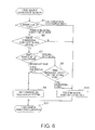
- a video display apparatus will now be described with reference to FIG. 7 .
- the video display apparatus according to the third embodiment differs from that according to the second embodiment in operation of the CPU 22. Operation of the CPU 22 is shown in FIG. 7 .
- the third embodiment has a flow obtained from the second embodiment by replacing the step S8 with step S8'. Operation of the CPU 22 shown in FIG. 7 also represents operation performed when video source changeover is performed irrespective of the kind of the current video source in the same way as the case of the second embodiment.
- the CPU 22 makes a decision in the video source decision unit 22c whether the video source after the changeover is a broadcast wave or an external input signal at the step S7. If the video source after the changeover is judged to be a broadcast wave, then the processing proceeds to the step S9 and the three-dimensional video display setting is performed in the same way as the second embodiment. On the other hand, if the video source after the changeover is judged to be an external input signal, then the processing proceeds to the step S8'.
- the video source decision unit 22c makes a decision whether the external input signal is a digital video or an analog video. If the external input signal is judged to be an analog video, then the processing proceeds to the step S10 and the two-dimensional video display setting unit 22e sets the two-dimensional video display. On the other hand, if the external input signal is judged at the step S8' to be a digital video, then the processing proceeds to the step S9 and the three-dimensional video display setting unit 22d sets the three-dimensional video display and sends an instruction to the display changeover unit 22f to display the three-dimensional video.
- the two-dimensional video display setting or the three-dimensional video display setting is performed on the basis of the current display mode, the contents of the three-dimensional video continuous viewing setting, and the video source after the changeover in the same way as the second embodiment as described heretofore.
- the three-dimensional video display setting or the two-dimensional video display setting is performed depending upon whether the video source after the changeover is a digital video or an analog video. As a result, the troublesome manual changeover manipulation becomes unnecessary when changing over the video source.
Landscapes
- Engineering & Computer Science (AREA)
- Multimedia (AREA)
- Signal Processing (AREA)
- Human Computer Interaction (AREA)
- Controls And Circuits For Display Device (AREA)
- Testing, Inspecting, Measuring Of Stereoscopic Televisions And Televisions (AREA)
- Transforming Electric Information Into Light Information (AREA)
- Closed-Circuit Television Systems (AREA)
Applications Claiming Priority (1)
| Application Number | Priority Date | Filing Date | Title |
|---|---|---|---|
| JP2011037389A JP5075996B2 (ja) | 2011-02-23 | 2011-02-23 | 映像表示方法および映像表示装置 |
Publications (2)
| Publication Number | Publication Date |
|---|---|
| EP2493201A2 true EP2493201A2 (de) | 2012-08-29 |
| EP2493201A3 EP2493201A3 (de) | 2013-04-24 |
Family
ID=44508917
Family Applications (1)
| Application Number | Title | Priority Date | Filing Date |
|---|---|---|---|
| EP11177317.2A Withdrawn EP2493201A3 (de) | 2011-02-23 | 2011-08-11 | Verfahren und Gerät zur Videoanzeige |
Country Status (3)
| Country | Link |
|---|---|
| US (1) | US20120212576A1 (de) |
| EP (1) | EP2493201A3 (de) |
| JP (1) | JP5075996B2 (de) |
Families Citing this family (1)
| Publication number | Priority date | Publication date | Assignee | Title |
|---|---|---|---|---|
| JP2013058847A (ja) * | 2011-09-07 | 2013-03-28 | Canon Inc | 表示装置、およびその制御方法 |
Family Cites Families (7)
| Publication number | Priority date | Publication date | Assignee | Title |
|---|---|---|---|---|
| CN1703915A (zh) * | 2002-09-27 | 2005-11-30 | 夏普株式会社 | 3-d图像显示单元,3-d图像记录装置和3-d图像记录方法 |
| KR100804572B1 (ko) * | 2002-09-27 | 2008-02-20 | 샤프 가부시키가이샤 | 입체화상 표시장치, 입체화상 기록장치, 입체화상 부호화장치, 입체화상 복호장치, 입체화상 기록방법 및 입체화상 전송방법 |
| US20080062069A1 (en) * | 2006-09-07 | 2008-03-13 | Icuiti Corporation | Personal Video Display Device |
| CN102510464B (zh) * | 2008-09-17 | 2015-04-22 | 松下电器产业株式会社 | 记录方法、再现装置和集成电路 |
| JP4525831B1 (ja) * | 2009-03-31 | 2010-08-18 | 株式会社カシオ日立モバイルコミュニケーションズ | 画像受信装置、および、プログラム |
| JP5274359B2 (ja) * | 2009-04-27 | 2013-08-28 | 三菱電機株式会社 | 立体映像および音声記録方法、立体映像および音声再生方法、立体映像および音声記録装置、立体映像および音声再生装置、立体映像および音声記録媒体 |
| US20110012993A1 (en) * | 2009-07-14 | 2011-01-20 | Panasonic Corporation | Image reproducing apparatus |
-
2011
- 2011-02-23 JP JP2011037389A patent/JP5075996B2/ja not_active Expired - Fee Related
- 2011-08-05 US US13/204,329 patent/US20120212576A1/en not_active Abandoned
- 2011-08-11 EP EP11177317.2A patent/EP2493201A3/de not_active Withdrawn
Non-Patent Citations (1)
| Title |
|---|
| None |
Also Published As
| Publication number | Publication date |
|---|---|
| EP2493201A3 (de) | 2013-04-24 |
| US20120212576A1 (en) | 2012-08-23 |
| JP2012175557A (ja) | 2012-09-10 |
| JP5075996B2 (ja) | 2012-11-21 |
Similar Documents
| Publication | Publication Date | Title |
|---|---|---|
| US20090089675A1 (en) | Method for providing graphical user interface and video apparatus using the same | |
| US8522296B2 (en) | Broadcast receiving apparatus and method for configuring the same according to configuration setting values received from outside | |
| US7538665B2 (en) | Remote-control system, remote controller, and display-control method | |
| JP5043379B2 (ja) | 放送受信/伝送デバイス、無線a/vシステム、および無線a/vシステムの制御方法 | |
| KR20110060464A (ko) | 오디오 출력 제어방법 및 이를 적용한 디지털 기기 | |
| US20140348485A1 (en) | Image signal processing apparatus and image signal processing method | |
| US11665397B2 (en) | Image display apparatus and method thereof | |
| EP2493201A2 (de) | Verfahren und Gerät zur Videoanzeige | |
| CN109791755B (zh) | 图像处理装置、显示装置及其控制方法 | |
| KR102782042B1 (ko) | 영상 표시 장치 및 그 동작방법 | |
| US8743133B2 (en) | Image processing system, image processing method, and program | |
| KR101356483B1 (ko) | 디지털 티브이의 오디오 볼륨 자동 조절 장치 및 방법 | |
| US8610829B2 (en) | Display system and method for reproduction of program contents | |
| US12598347B2 (en) | Signal processing device and image display apparatus including the same | |
| US12294807B2 (en) | A/V receiving apparatus and wireless display system | |
| US20100050224A1 (en) | Display apparatus and control method thereof | |
| US12483831B2 (en) | Wireless audio transmission device, wireless sound output device, and system having same | |
| US12003315B2 (en) | Broadcast reception device and operating method therefor | |
| KR102423567B1 (ko) | 디스플레이 장치 | |
| US20230205324A1 (en) | Image display device and method for operating same | |
| KR100747842B1 (ko) | 영상 표시 장치에서 화면 크기 변경에 따른 음성 선택방법 | |
| JP2006319797A (ja) | 放送受信装置及びリモコン | |
| EP2424232A2 (de) | Verfahren und Vorrichtung zum Umschalten eines Rundfunkkanals für eine 2D/3D umschaltbare Anzeigevorrichtung | |
| JP2010087620A (ja) | 映像処理装置及び映像処理方法 | |
| KR20100050988A (ko) | 오디오 신호 처리 방법 및 이를 이용한 방송 출력 장치 |
Legal Events
| Date | Code | Title | Description |
|---|---|---|---|
| PUAI | Public reference made under article 153(3) epc to a published international application that has entered the european phase |
Free format text: ORIGINAL CODE: 0009012 |
|
| 17P | Request for examination filed |
Effective date: 20110811 |
|
| AK | Designated contracting states |
Kind code of ref document: A2 Designated state(s): AL AT BE BG CH CY CZ DE DK EE ES FI FR GB GR HR HU IE IS IT LI LT LU LV MC MK MT NL NO PL PT RO RS SE SI SK SM TR |
|
| AX | Request for extension of the european patent |
Extension state: BA ME |
|
| PUAL | Search report despatched |
Free format text: ORIGINAL CODE: 0009013 |
|
| AK | Designated contracting states |
Kind code of ref document: A3 Designated state(s): AL AT BE BG CH CY CZ DE DK EE ES FI FR GB GR HR HU IE IS IT LI LT LU LV MC MK MT NL NO PL PT RO RS SE SI SK SM TR |
|
| AX | Request for extension of the european patent |
Extension state: BA ME |
|
| RIC1 | Information provided on ipc code assigned before grant |
Ipc: H04N 13/04 20060101ALI20130320BHEP Ipc: H04N 13/00 20060101AFI20130320BHEP Ipc: H04N 21/81 20110101ALI20130320BHEP |
|
| STAA | Information on the status of an ep patent application or granted ep patent |
Free format text: STATUS: THE APPLICATION IS DEEMED TO BE WITHDRAWN |
|
| 18D | Application deemed to be withdrawn |
Effective date: 20160301 |