EP2493680B1 - Anlage zur herstellung eines festprodukts mithilfe eines oder mehrerer pulvermaterialien - Google Patents
Anlage zur herstellung eines festprodukts mithilfe eines oder mehrerer pulvermaterialien Download PDFInfo
- Publication number
- EP2493680B1 EP2493680B1 EP10788108.8A EP10788108A EP2493680B1 EP 2493680 B1 EP2493680 B1 EP 2493680B1 EP 10788108 A EP10788108 A EP 10788108A EP 2493680 B1 EP2493680 B1 EP 2493680B1
- Authority
- EP
- European Patent Office
- Prior art keywords
- punch
- die
- solid product
- punches
- press
- Prior art date
- Legal status (The legal status is an assumption and is not a legal conclusion. Google has not performed a legal analysis and makes no representation as to the accuracy of the status listed.)
- Active
Links
Images



Classifications
-
- B—PERFORMING OPERATIONS; TRANSPORTING
- B30—PRESSES
- B30B—PRESSES IN GENERAL
- B30B1/00—Presses, using a press ram, characterised by the features of the drive therefor, pressure being transmitted directly, or through simple thrust or tension members only, to the press ram or platen
- B30B1/18—Presses, using a press ram, characterised by the features of the drive therefor, pressure being transmitted directly, or through simple thrust or tension members only, to the press ram or platen by screw means
-
- B—PERFORMING OPERATIONS; TRANSPORTING
- B30—PRESSES
- B30B—PRESSES IN GENERAL
- B30B11/00—Presses specially adapted for forming shaped articles from material in particulate or plastic state, e.g. briquetting presses, tabletting presses
- B30B11/005—Control arrangements
-
- B—PERFORMING OPERATIONS; TRANSPORTING
- B30—PRESSES
- B30B—PRESSES IN GENERAL
- B30B11/00—Presses specially adapted for forming shaped articles from material in particulate or plastic state, e.g. briquetting presses, tabletting presses
- B30B11/02—Presses specially adapted for forming shaped articles from material in particulate or plastic state, e.g. briquetting presses, tabletting presses using a ram exerting pressure on the material in a moulding space
- B30B11/04—Presses specially adapted for forming shaped articles from material in particulate or plastic state, e.g. briquetting presses, tabletting presses using a ram exerting pressure on the material in a moulding space co-operating with a fixed mould
- B30B11/06—Presses specially adapted for forming shaped articles from material in particulate or plastic state, e.g. briquetting presses, tabletting presses using a ram exerting pressure on the material in a moulding space co-operating with a fixed mould each charge of the material being compressed against the previously formed body
-
- B—PERFORMING OPERATIONS; TRANSPORTING
- B30—PRESSES
- B30B—PRESSES IN GENERAL
- B30B15/00—Details of, or accessories for, presses; Auxiliary measures in connection with pressing
- B30B15/0094—Press load monitoring means
-
- B—PERFORMING OPERATIONS; TRANSPORTING
- B30—PRESSES
- B30B—PRESSES IN GENERAL
- B30B15/00—Details of, or accessories for, presses; Auxiliary measures in connection with pressing
- B30B15/30—Feeding material to presses
- B30B15/302—Feeding material in particulate or plastic state to moulding presses
- B30B15/304—Feeding material in particulate or plastic state to moulding presses by using feed frames or shoes with relative movement with regard to the mould or moulds
- B30B15/306—Feeding material in particulate or plastic state to moulding presses by using feed frames or shoes with relative movement with regard to the mould or moulds for multi-layer articles
Definitions
- the invention relates to an installation making it possible to produce, from one or more pulverulent materials, a solid, monolayer or multilayer product.
- Each of said punches is motorized such as for example by means of a connecting rod-crank member, making it possible to vary the height of translation of said punches, and consequently, the compression ratio.
- the filling of the matrix with powder is carried out by specific positioning of the lower punch, and the compression is carried out by actuating the upper punch so as to cause it to descend into said matrix.
- Tablet production machines typically vary the translation height of the punches by a continuous system for driving the punches in rotation by a turret and for compression by rollers. This device is more difficult to use in R&D because of the minimum volume of powder required as well as by the mechanical stresses that this type of rotary press imposes on the tablet.
- EP-0358770A1 discloses a press provided with the characteristics of the preamble of claim 1. If undoubtedly, this improvement constitutes a significant improvement compared to the devices of the prior art, (extremely expensive hydraulic presses), it is however complex to carry out , and expensive to produce.
- the objective of the present invention is to provide a device of the type in question, which is both simpler to produce and therefore less expensive, while offering a certain reliability in terms of compression.
- the devices known to date do not make it possible to produce such multilayer tablets in a reliable manner, that is to say, without risking the return of one, or even of several of the intermediate layers in the pulverulent state, or by ignoring the dosing / shaving function.
- the lower punch is associated with a system for uncoupling the means or members ensuring its movement, said system itself being provided with a brake, capable of limiting the stroke of said punch towards the bottom in order to preserve the contact of said punch with the pulverulent material present in the matrix during the production of the solid product, in particular multilayer, and as a corollary, so as not to generate additional compression during the displacement in the matrix of the various amalgams of pulverulent product during the intermediate phases of filling for each layer of product.
- the lower punch enjoys a certain freedom or a certain clearance with respect to the member or members which ensure its movement, this clearance obviously extending in the same direction as the direction of displacement of said piston.
- the purpose of the brake referred to above is to counterbalance the weight of said piston, so that, during the filling and packing stages of the pulverulent material, in particular for the production of multilayer tablets, to systematically keep the upper end of said piston in contact with the pulverulent product then added and by its adjustment to dose the settlement induced by the displacement.
- the upper punch is movable in translation only between two positions, respectively high and low, said upper punch being static during the compression phase (s).
- This variant is simple to produce and implement, and therefore inexpensive while allowing the production of multilayer tablets.
- the upper punch does not play a positive role during the compression step or steps, this role being assigned only to the lower punch.
- the upper punch therefore only fulfills a feedback function when the lower punch is actuated. It will be described in the context of the detailed description of the invention, the additional role of the upper punch, tending to compact the pulverulent material then introduced into the matrix, ie in contact with the lower layer produced during the previous compression step. , or in contact with the upper end of the lower punch when the first layer is produced.
- the displacement of the upper punch is controlled at any time, thus making it possible to have more flexibility and the possibility of having a fixed or mobile upper punch during the compression phase.
- the lower punch is driven in a translational movement at the level of the die by means of a ball or roller screw actuated by an electric motor.
- said lower punch is therefore driven in an upward or downward translational movement, directly by means acting directly on said punch, in the absence of any intermediate element of the cam, universal joint or other type.
- the implementation of such a ball or roller screw system makes it possible to have high power over a reduced distance, and as a corollary to generate a very low inertia, capable of promoting the compression cycles over a period of time. particularly reduced.
- the load capacity and therefore the pressure that can be applied can reach very high values, typically more than 10 tonnes.
- the compression occurs by the lower punch, unlike all the devices of the prior art which implement compression by the upper punch.
- the main advantages of the invention therefore lie in the control of the dosage by displacement of the lower punch and the possibility of manufacturing multilayer tablets by associating the declutching with brake of said lower punch.
- the lower punch is associated with a lower carriage, movable in translation, in this case ascending and descending, and guided at the level of ball guide columns mounted within the frame receiving the installation in question.
- the upper punch is movable only between two positions, respectively high and low. This movement is ensured by means of a rod-crank type system, the high position being implemented when the matrix is fed with the pulverulent material or materials and when the solid product is ejected. out of the matrix.
- the upper punch may itself be subjected to the action of a ball or roller screw system, also actuated by an electric motor, when it is desired to complexify the compression cycle.
- a ball or roller screw system also actuated by an electric motor, when it is desired to complexify the compression cycle.
- the advantages inherent in the implementation of such a system are identical to those described in relation to the lower punch. This combination of movements advantageously makes it possible to simulate the movement of the punches on rotary production presses with very little pulverulent material.
- the electric motor or motors actuating the ball or roller screw is of the brushless type and are advantageously coupled to a programmable variator, so as to control and synchronize the movement of the lower punch and, if necessary, the upper punch.
- the support of the lower and upper punches is provided with a force sensor making it possible to measure the compression ratio exerted and to adjust the installation.
- this measurement system may consist of one or more sensors for linear measurement of the movement of the punches, intended to determine the respective position of the lower and upper punches, and consequently the filling height of the matrix of material. pulverulent and the thickness of the solid product produced.
- This installation basically comprises a frame (1), in particular metallic, resting on the ground by means of a base.
- This frame (1) includes a vertical guide system ensuring the precision of the movement of the punches described below.
- this system comprises two vertical hollow columns (3, 4), making it possible to house the means for guiding the essential mobile members of the installation.
- These two columns (3) and (4) are attached to either side of a table (5), one of the primary functions of which is to secure the matrix within which are intended to be produced solid products according to the invention.
- it has two bores (6) formed within its thickness, and each capable of receiving a screw for fixing a matrix holder, thus allowing the interchangeability of the matrix and consequently, allowing '' adapt the installation to the shape of the desired solid product.
- the installation comprises a lower punch (7) and an upper punch (8) intended to cooperate within the matrix (9), in order to ensure the compression of the pulverulent material previously introduced into the matrix and as a corollary, the production of a solid product, in this case a tablet.
- the lower punch (7) is associated with a movable carriage (10) capable of moving between the columns (3) and (4) of the frame. More specifically, this mobile carriage is provided at its two ends with ball guides (11) cooperating with two guide columns (12) parallel to each other and fixed within the columns respectively (3) and (4). Due to the precision of these ball guides, it is possible to dispense with any punch guide system proper, the adjustment being carried out during construction.
- the mobile carriage (10) is moved in upward or downward translation by means of a ball screw or satellite roller (13), itself driven in rotation by means of an electric motor (14) of brushless type. To this end, it is secured at its lower end to a pulley (16) rotated by said motor (14) by means of a toothed belt (15).
- Ball or satellite roller screws are of a type known per se, so there is no need to describe them here in more detail. It should simply be recalled that they constitute a mechanism ensuring the conversion of a rotational movement into a translational movement according to a helical connection. They allow power transmission while ensuring the precision required in terms of displacement of said translation.
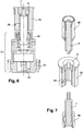
- the lower punch (7) is associated with a declutching and brake system (39), in this case constituted by an adjustable spring acting radially on said punch, intended to limit its stroke towards the bottom.
- a declutching and brake system 39
- the lower punch is in contact with the screw (13) and the lower mobile carriage (10) only in the upward or upward direction, said screw (13) and the mobile carriage (10) being able by this declutching system descending a fixed length without action on said punch, the latter being held by the brake - spring (39), also adjustable, to maintain the punch in contact with the powder and effect a first compaction on the latter.
- adjustable intensity is also adjustable, to maintain the punch in contact with the powder and effect a first compaction on the latter.
- the upper punch (8) only performs the feedback function when it cooperates with the lower punch (7) within the die. In doing so, and in this embodiment, it is only animated in an upward movement to allow the filling of the matrix with pulverulent product and the ejection of the tablet once produced. It is animated in a descending movement and only enters the matrix to take its position without exerting any notorious force (see above). It therefore works in principle "all or nothing" using a rod-crank assembly (20), actuated by an electric motor (18), and acting on an upper carriage (21), itself received at the level guide columns (22) like the lower carriage (10).
- said upper carriage (21) is also received, unlike the lower carriage, on external springs (23) so as to balance the weight of the assembly.
- two adjustable compression springs (23) are secured to the carriage (21) at each of its ends to balance the entire carriage and its equipment. This device also provides security against the fall of the carriage in the event of an electrical system failure.
- Figure 8a zero stage, that is to say that a previous stage in the production of such a tablet ended with the ejection of the tablet obtained: the upper end of the lower punch (7) is flush with the upper face of the table (5), and as a corollary, with the upper end of the die. The upper punch (8) is in the high position, to allow this ejection step.
- Figure 8b The upper punch is held in the high position, and as a corollary, the members ensuring the movement of the lower punch are lowered. Due to the disengagement of these members with respect to the punch, in addition to the presence of the brake (39), said lower punch only lowers partially, in any case sufficient to release the volume necessary for filling with the pulverulent material constituting the lower layer of the bilayer tablet to be produced.
- Figure 8c the bodies ensuring the displacement of the lower punch (7) go back, so as to induce the upward thrust of the latter, and as a corollary allow the metering and leveling of the excess powdery material.
- Figure 8d the displacement members of the lower punch are lowered again, but the said punch remains substantially in place, due to the brake and clutch release with respect to said members.
- Figure 8e the upper punch (8) is lowered, enters the matrix, ensuring a "light” compaction of the material present in the matrix, the lower punch descending slowly, slowed down by the brake, the adjustment of which controls the intensity of compaction.
- Figure 8f compression step: the lower punch is raised under the action of the organs ensuring its movement, and as a corollary, the upper punch, then in the low position, provides the feedback: the first layer of the tablet is thus produced.
- Figure 8g the upper punch is raised to the high position, without the lower piston being released from the organs ensuring its progression: it therefore remains in its place.
- Figure 8h due to the retraction of the upper punch, access to the matrix is freed, the volume of which is partially filled by said lower layer of the tablet: a a new step of filling said matrix with a second pulverulent material is carried out.
- Figure 8i new leveling step: identical to the figure 8c .
- Figure 8j identical to the figure 8d : the lower punch is released from the action of the organs ensuring its movement, but is held in place by the brake (39).
- Figure 8k identical to the figure 8e : soft packing of the second pulverulent material in contact with said lower layer, following the descent of the upper punch into its lower position.
- Figure 8l identical to the figure 8f : compression of the second layer of the tablet by raising the lower punch, with an exerted force capable of reaching 10 tonnes.
- Figure 8m the upper punch is repositioned in its upper position, and the lower punch goes up in turn, pushing the bilayer tablet thus produced out of the matrix, then allowing the ejection of the latter.
- the upper punch (8) after having been retracted to allow the introduction of a new quantity of pulverulent material capable of constituting the second layer, then reintroduced into the matrix, induces the displacement inside the matrix, and therefore in the downward direction, of the precompressed powder bed thus produced, when the lower punch adopts its low position.
- This positioning is obtained using the freedom provided by the system.
- the brushless motor associated with the ball screw allows the programming and the control of the movement of the associated punch.
- This control associated with the synchronization of the two punches allows a reproduction of the movement over time of the punches, allowing the reproduction of the displacements of the elements of the so-called rotary machines during the various phases of production of the tablets.
- each powder or pulverulent material reacts differently to the movements of the punches (reduction in volume of the powder bed within the matrix), and therefore as a corollary to the pressure exerted. It is therefore necessary to be able to act on the displacement of the punches, and in the described embodiment of the lower punch as a function of the force measured at the level of the powder.
- This force is only the reaction force of the powder to the reduction in volume imparted by the relative movement of the punches.
- An external system typically consisting of an electronic servo control at the level of which the measurements carried out by the sensors lead, controls the force and the displacement of the punches, and at the very least of the lower punch, thus making it possible to influence said displacement as a function of the resulting compressive force measured (for example displacement stopped as soon as a force level is reached).
- the carriage (10) receives a sensor support (19) integrating a force sensor proper (28), typically consisting of a strain gauge, and making it possible to calibrate the force exerted by the lower punch.
- a force sensor proper typically consisting of a strain gauge
- the brushless motor (14) is equipped with a brake or a torque support, capable of opposing a torque close to 80 N / m.
- This brake can be integrated into the engine or external to it, and this, in a known manner.
- the system therefore makes it possible to control the displacement of the lower punch as a function of the two modes of behavior of the pulverulent materials described above.
- a sensor holder (24) is integral with the carriage (21) integrating a force sensor proper of a type similar to that associated with the lower carriage (10) and making it possible to determine, in cooperation with the latter, the stress and therefore the pressure exerted on the pulverulent material, and consequently the displacement of said lower punch.
- This first embodiment corresponds to a simplified mode of installation of the invention. It implements the essential principle targeted by the invention, namely the compression of the pulverulent material from below, associated with a braking and declutching system for the lower punch, which is particularly innovative with regard to the prior art. .
- the lower punch (7) ensures the filling / dosing phases, due to its free travel, and compression.
- FIGS. 3 and 4 are views analogous to Figures 1 and 2 , except that the displacement of the upper punch (8) is, in this particular embodiment, also achieved by a ball screw or satellite roller type of the screw (13) animating in translation the lower punch.
- This more expensive realization brings many advantages in terms of control and simulation of production presses with symmetrical movements.
- this screw (not shown so as not to overload the figure) is driven in rotation by means of a brushless electric motor (25) actuating a pulley (26) by means of a toothed belt (27).
- the models implemented by the installation of the invention can either completely simulate the behavior of industrial production machines (traditionally controlled on the move on rotary presses), or compress using force as the only control element in order to have a tablet density independent of the variations inherent in filling.
Landscapes
- Engineering & Computer Science (AREA)
- Mechanical Engineering (AREA)
- Medical Preparation Storing Or Oral Administration Devices (AREA)
- Medicinal Preparation (AREA)
- Processing And Handling Of Plastics And Other Materials For Molding In General (AREA)
- Press Drives And Press Lines (AREA)
Claims (9)
- Ein- Stempel- Simulationspresse für industrielle Pressen zur Herstellung eines Festproduktes aus einem oder mehreren Pulvermaterialien, die umfasst:• Zufuhrvorrichtungen (31, 32, 38) für Material(ien);• eine Aufnahmematrize (9) für das oder die Pulvermaterialien, mit der Form des herzustellenden Festproduktes, vorteilhafterweise reversibel an einem Stanzsatteltisch (5) befestigt, der mit dem Pressenrahmen fest verbunden ist;• ein oberer Stempel (8) und ein unterer Stempel (7), angetrieben durch eine Längsbewegung, die miteinander in Höhe dieser Aufnahmematrize (9) zusammenarbeiten können, um die Kompression des oder der Pulvermaterialien und die Herstellung des Festproduktes zu gewährleisten;dadurch gekennzeichnet, dass :• der Unterstempel (7) mit einem System zum Entkoppeln der Vorrichtungen oder Organe verbunden ist, die für seine Bewegung sorgen, wobei diese Vorrichtungen oder Organe aus einem Unterschlitten (10) besteht, der in Längsrichtung mobil ist und auf Höhe von Führungssäulen einer Kugelführung (11, 12), montiert innerhalb des Presserahmens, geführt wird, dieser mobile Unterschlitten (10) wird selbst in Längsrichtung über eine Kugelrollspindel oder ein Rollengewinde (13) bewegt, angetrieben über einen Elektromotor, wodurch sich dieser Unterstempel in Höhe der Matrize (9) verschiebt;• dadurch, dass dieser Unterstempel (7) nicht fest mit dem genannten mobilen Unterschlitten (10) verbunden ist;• dadurch, dass der Unterstempel (7) mit einem Kupplungs- und Bremssystem (39) verbunden ist, das aus einer einstellbaren Feder besteht, die radial auf diesen Stempel wirkt und seinen Hubweg nach unten in einer Art und Weise begrenzen soll, dass dieser Unterstempel (7) nur in aufsteigender oder Aufwärtsrichtung Kontakt zur Schraube und dem mobilen Unterschlitten (10) hat, diese Schraube (13) und der mobile Unterschlitten (10) können über dieses Kupplungs- und Bremssystem sich über eine feste Länge hinweg wieder senken, ohne auf diesen Stempel einzuwirken, da dieser durch die Bremse - Feder (39) gehalten wird, damit der Stempel bei der Herstellung des Festproduktes in Kontakt mit dem Pulvermaterial in der Matrize bleibt um dieses ein erstes Mal, mit einstellbarer Stärke zu komprimieren; das untere Endstück des genannten Unterstempels (7) hat also mit dem genannten mobilen Unterschlitten (10) nur in den Kompressions-, Dosier- und Auswurfphasen Kontakt.
- Ein- Stempel- Simulationspresse nach Anspruch 1, dadurch gekennzeichnet, dass der Oberstempel (8) in Längsrichtung nur zwischen zwei Positionen mobil ist und zwar oben und unten, da dieser Oberstempel bei der oder den Kompressionsphasen statisch ist.
- Ein- Stempel- Simulationspresse nach Anspruch 2, dadurch gekennzeichnet, dass der Oberstempel (8) in Längsrichtung über ein System vom Typ Kurbeltrieb (20) mobil ist, die obere Position wird eingenommen, wenn die Matrize mit dem oder den Pulvermaterialien gefüllt wird sowie beim Auswerfen des Festproduktes aus der Matrize, und die untere Position wird während der Verdichtungsphasen des Pulverproduktes eingenommen.
- Ein- Stempel- Simulationspresse nach Anspruch 1, dadurch gekennzeichnet, dass die Bewegung des Oberstempels (8) zu jeder Zeit gesteuert wird.
- Ein- Stempel- Simulationspresse nach Anspruch 4, dadurch gekennzeichnet, dass der Oberstempel (8) in Längsrichtung in Höhe der Matrize über eine Kugelrollspindel oder ein Rollengewinde bewegt wird, das von einem Elektromotor angetrieben wird.
- Ein- Stempel- Simulationspresse nach einem der Ansprüche 1 bis 5, dadurch gekennzeichnet, dass es sich bei dem Elektromotor, der die Kugelrollspindel oder das Rollengewinde antreibt, um einen Brushless-Typ handelt, der mit einem programmierbaren Regler verbunden ist, so dass die Bewegungen des Unterstempels (7) und auch des Oberstempels (8), gesteuert und synchronisiert werden können.
- Ein- Stempel- Simulationspresse nach einem der Ansprüche 1 bis 6, dadurch gekennzeichnet, dass die Halterung der Unter- (7) und Oberstempel (8) einen Kraftaufnehmer enthält, mit dem der Grad der ausgeübten Kompression gemessen und die Presse eingestellt werden kann.
- Ein- Stempel- Simulationspresse nach einem der Ansprüche 1 bis 7, dadurch gekennzeichnet, dass sie außerdem einen oder mehrere lineare Messfühler für die Stempelbewegung enthält, mit denen die jeweilige Position des unteren und oberen Stempels und gleichzeitig die Füllhöhe der Matrize mit Pulver und die Dicke des hergestellten Festproduktes bestimmt werden können.
- Ein- Stempel- Simulationspresse nach Anspruch 8, dadurch gekennzeichnet, dass die Bewegung des unteren und oberen Stempels nach Position oder Kraft gesteuert werden kann oder alternativ nach Position und Kraft, über eine externe elektronische Regelung.
Applications Claiming Priority (2)
| Application Number | Priority Date | Filing Date | Title |
|---|---|---|---|
| FR0957643A FR2951989B1 (fr) | 2009-10-30 | 2009-10-30 | Installation pour la realisation d'un produit solide a partir d'un ou de plusieurs materiaux pulverulents |
| PCT/FR2010/052314 WO2011051626A1 (fr) | 2009-10-30 | 2010-10-28 | Installation pour la réalisation d'un produit solide à partir d'un ou de plusieurs matériaux pulvérulents |
Publications (2)
| Publication Number | Publication Date |
|---|---|
| EP2493680A1 EP2493680A1 (de) | 2012-09-05 |
| EP2493680B1 true EP2493680B1 (de) | 2020-03-11 |
Family
ID=42174329
Family Applications (1)
| Application Number | Title | Priority Date | Filing Date |
|---|---|---|---|
| EP10788108.8A Active EP2493680B1 (de) | 2009-10-30 | 2010-10-28 | Anlage zur herstellung eines festprodukts mithilfe eines oder mehrerer pulvermaterialien |
Country Status (4)
| Country | Link |
|---|---|
| US (1) | US8668483B2 (de) |
| EP (1) | EP2493680B1 (de) |
| FR (1) | FR2951989B1 (de) |
| WO (1) | WO2011051626A1 (de) |
Families Citing this family (13)
| Publication number | Priority date | Publication date | Assignee | Title |
|---|---|---|---|---|
| DE102011116548B4 (de) | 2011-10-21 | 2014-05-15 | Fette Compacting Gmbh | Presse |
| DE102011116552B4 (de) | 2011-10-21 | 2015-08-20 | Fette Compacting Gmbh | Presse |
| DE102012010767A1 (de) * | 2012-05-31 | 2013-12-05 | Fette Compacting Gmbh | Presse |
| DE102013114693A1 (de) * | 2013-12-20 | 2015-06-25 | Fette Engineering GmbH | Stopfstempelstation und Verfahren zum Füllen von Kapseln in einer Stopfstempelstation |
| DE102014006374A1 (de) * | 2014-05-05 | 2015-11-05 | Gkn Sinter Metals Engineering Gmbh | Vorrichtung zur Herstellung eines Rohlings nebst Verfahren hierzu und Rohling |
| FR3021805B1 (fr) * | 2014-05-27 | 2019-05-03 | Commissariat A L'energie Atomique Et Aux Energies Alternatives | Presse pour mettre en forme des pastilles dans un environnement restreint et hostile et procede d'assemblage de la presse |
| JP6344360B2 (ja) * | 2015-10-06 | 2018-06-20 | トヨタ自動車株式会社 | 粉末成形装置の制御方法 |
| GB2543579B (en) * | 2015-10-23 | 2018-06-06 | Gamlen Michael | Pivoting tablet die |
| CA3125792C (en) * | 2019-01-07 | 2024-05-14 | Fritz Schmitt | Device for tableting a powder, liquid, paste, encapsulated or granular active ingredient composition |
| CN109849398A (zh) * | 2019-01-16 | 2019-06-07 | 陕西理工大学 | 一种螺距任意可调的螺旋伺服压力机 |
| CN109719988B (zh) * | 2019-03-08 | 2024-02-13 | 萍乡鹏华液压机械制造有限公司 | 全自动圆刀片干粉液压机 |
| CH716048B1 (de) * | 2019-04-09 | 2024-02-15 | Dietmar Kramer Dr Sc Techn Eth Phd | Verfahren sowie eine Messeinrichtung zum Ausmessen von Utensilien für Pressen. |
| CN111941912A (zh) * | 2020-08-17 | 2020-11-17 | 南通中液液压机有限公司 | 多种粉料全自动液压机 |
Family Cites Families (17)
| Publication number | Priority date | Publication date | Assignee | Title |
|---|---|---|---|---|
| GB952006A (en) * | 1962-02-21 | 1964-03-11 | John Holroyd & Company Ltd | Multi-layer tablet making machines |
| US3353215A (en) * | 1965-11-10 | 1967-11-21 | Haller John | Powdered material briquetting press |
| US4104014A (en) * | 1977-07-13 | 1978-08-01 | Key Industries | Punch for compressing machine |
| SU935313A1 (ru) * | 1979-05-10 | 1982-06-15 | Предприятие П/Я В-8857 | Роторный пресс дл прессовани порошковых материалов |
| JP2519498B2 (ja) * | 1988-01-16 | 1996-07-31 | ファナック株式会社 | 電動式粉末成形機 |
| US5211964A (en) * | 1991-05-20 | 1993-05-18 | Westinghouse Electric Corp. | Press machine with means to adjust punching force |
| DE4428842C1 (de) * | 1994-08-02 | 1996-01-18 | Mannesmann Ag | Vorrichtung zur Herstellung von Preßkörpern |
| JPH1043889A (ja) * | 1996-07-31 | 1998-02-17 | Tsukuba Seiko Kk | プレス機用連動機構 |
| EP0893239B1 (de) * | 1997-07-23 | 2002-07-31 | KILIAN & Co. GmbH | Rundlauf-Tablettenpresse |
| US6106262A (en) * | 1997-12-25 | 2000-08-22 | Metropolitan Computing Corporation | Press simulation apparatus |
| FR2791602B1 (fr) | 1999-03-31 | 2001-05-11 | Medelco | Dispositif de fabrication d'un produit solide a partir d'une matiere pulverulente |
| DE19919693C2 (de) * | 1999-04-30 | 2001-08-23 | Fette Wilhelm Gmbh | Verfahren zur Positionsbestimmung eines Preßstempels einer Pulverpresse |
| FR2855094B1 (fr) | 2003-05-20 | 2006-04-28 | Medelco | Installation pour la realisation d'un produit solide a partir d'un materiau pulverulent |
| ES2452022T3 (es) * | 2006-02-06 | 2014-03-31 | Abb Research Ltd. | Sistema de línea de prensas y método |
| WO2008104969A1 (en) * | 2007-02-26 | 2008-09-04 | Polygon-Tamarisk Ltd | Press for producing powder based parts using compaction |
| DE102008015820B4 (de) * | 2008-03-27 | 2013-02-28 | Fette Compacting Gmbh | Vorrichtung und Verfahren zur Messung der vertikalen Position von Ober- und Unterstempeln einer Rundläufer-Tablettenpresse |
| DE102008035301B3 (de) * | 2008-07-29 | 2010-03-25 | Fette Gmbh | Pulverpresse |
-
2009
- 2009-10-30 FR FR0957643A patent/FR2951989B1/fr active Active
-
2010
- 2010-10-28 WO PCT/FR2010/052314 patent/WO2011051626A1/fr not_active Ceased
- 2010-10-28 EP EP10788108.8A patent/EP2493680B1/de active Active
-
2012
- 2012-04-26 US US13/456,846 patent/US8668483B2/en active Active
Non-Patent Citations (1)
| Title |
|---|
| None * |
Also Published As
| Publication number | Publication date |
|---|---|
| US8668483B2 (en) | 2014-03-11 |
| EP2493680A1 (de) | 2012-09-05 |
| FR2951989B1 (fr) | 2012-02-03 |
| WO2011051626A1 (fr) | 2011-05-05 |
| FR2951989A1 (fr) | 2011-05-06 |
| US20120207867A1 (en) | 2012-08-16 |
Similar Documents
| Publication | Publication Date | Title |
|---|---|---|
| WO2011051626A1 (fr) | Installation pour la réalisation d'un produit solide à partir d'un ou de plusieurs matériaux pulvérulents | |
| EP2454040B1 (de) | Vorrichtung um dünne filme herzustellen und verfahren um solch eine vorrichtung zu verwenden | |
| EP0365447B1 (de) | Verfahren und Vorrichtung zum Zusammenpressen und Steuern der Zusammenpressung von pulverförmigen Materialien und Presse zur Anwendung in diesem Verfahren | |
| FR2584046A1 (fr) | Procede et installation pour produire des garnitures d'emballage | |
| WO2020239553A1 (fr) | Machine de fabrication additive a distribution de poudre par tamisage | |
| WO2004037704A1 (fr) | Dispositif a roulements pour deplacer une charge dans un plan sensiblement horizontal | |
| JP7471405B2 (ja) | タブレットプレス機および圧縮方法 | |
| EP1631447A1 (de) | Anlage zur herstellung eines festen produktes aus einem pulverförmigen rohstoff | |
| EP2879820A2 (de) | Maschine zur herstellung eines pulverförmigen zusatzstoffs | |
| EP1937462B1 (de) | Pulverspender, insbesondere für pelletpresse und verfahren zur herstellung von kernbrennstofftabletten | |
| FR2569653A1 (fr) | Procede pour commander le remplissage d'un recipient et dispositif pour sa mise en oeuvre | |
| WO2023025893A1 (fr) | Contrôle d'impression 3d | |
| EP1971814B1 (de) | Vorrichtung zur trennung von sinterschiffchen | |
| FR2549403A1 (fr) | Presse pour le forgeage et l'estampage | |
| WO2010146100A1 (fr) | Procédé et dispositif de fabrication de produits compactés par compaction lente | |
| EP1600285B1 (de) | Vorrichtung zur Herstellung von Pastillen durch Zusammenpressen | |
| JP5491257B2 (ja) | 回転プレス機のプレス・ステーション | |
| FR2629448A1 (fr) | Appareillage pour decouper une piece en un materiau du type verre ou ceramique le long d'une ligne incisee | |
| EP2403669A2 (de) | Presswerkzeug | |
| FR2791602A1 (fr) | Dispositif de fabrication d'un produit solide a partir d'une matiere pulverulente | |
| FR2661343A1 (fr) | Procede et machine pour la fabrication d'un produit fritte avec reglage des parametres en continu. | |
| FR3004125A1 (fr) | Machine a granuler | |
| FR2872447A1 (fr) | Dispositif de compactage de poudre pour la fabrication de pastilles | |
| FR3068289A1 (fr) | Installation pour la realisation d'un produit a partir d'un ou plusieurs materiaux pulverulents | |
| FR2937892A1 (fr) | Dispositif de fabrication d'une brique compressee et brique obtenue par un tel dispositif |
Legal Events
| Date | Code | Title | Description |
|---|---|---|---|
| PUAI | Public reference made under article 153(3) epc to a published international application that has entered the european phase |
Free format text: ORIGINAL CODE: 0009012 |
|
| 17P | Request for examination filed |
Effective date: 20120426 |
|
| AK | Designated contracting states |
Kind code of ref document: A1 Designated state(s): AL AT BE BG CH CY CZ DE DK EE ES FI FR GB GR HR HU IE IS IT LI LT LU LV MC MK MT NL NO PL PT RO RS SE SI SK SM TR |
|
| DAX | Request for extension of the european patent (deleted) | ||
| STAA | Information on the status of an ep patent application or granted ep patent |
Free format text: STATUS: EXAMINATION IS IN PROGRESS |
|
| 17Q | First examination report despatched |
Effective date: 20180827 |
|
| REG | Reference to a national code |
Ref country code: DE Ref legal event code: R079 Ref document number: 602010063473 Country of ref document: DE Free format text: PREVIOUS MAIN CLASS: B30B0001180000 Ipc: B30B0011020000 |
|
| RIC1 | Information provided on ipc code assigned before grant |
Ipc: B30B 15/30 20060101ALI20190404BHEP Ipc: B30B 11/06 20060101ALI20190404BHEP Ipc: B30B 1/18 20060101ALI20190404BHEP Ipc: B30B 11/00 20060101ALI20190404BHEP Ipc: B30B 11/02 20060101AFI20190404BHEP |
|
| APBK | Appeal reference recorded |
Free format text: ORIGINAL CODE: EPIDOSNREFNE |
|
| APBN | Date of receipt of notice of appeal recorded |
Free format text: ORIGINAL CODE: EPIDOSNNOA2E |
|
| APBR | Date of receipt of statement of grounds of appeal recorded |
Free format text: ORIGINAL CODE: EPIDOSNNOA3E |
|
| APBV | Interlocutory revision of appeal recorded |
Free format text: ORIGINAL CODE: EPIDOSNIRAPE |
|
| GRAP | Despatch of communication of intention to grant a patent |
Free format text: ORIGINAL CODE: EPIDOSNIGR1 |
|
| STAA | Information on the status of an ep patent application or granted ep patent |
Free format text: STATUS: GRANT OF PATENT IS INTENDED |
|
| INTG | Intention to grant announced |
Effective date: 20191111 |
|
| GRAS | Grant fee paid |
Free format text: ORIGINAL CODE: EPIDOSNIGR3 |
|
| GRAA | (expected) grant |
Free format text: ORIGINAL CODE: 0009210 |
|
| STAA | Information on the status of an ep patent application or granted ep patent |
Free format text: STATUS: THE PATENT HAS BEEN GRANTED |
|
| AK | Designated contracting states |
Kind code of ref document: B1 Designated state(s): AL AT BE BG CH CY CZ DE DK EE ES FI FR GB GR HR HU IE IS IT LI LT LU LV MC MK MT NL NO PL PT RO RS SE SI SK SM TR |
|
| REG | Reference to a national code |
Ref country code: GB Ref legal event code: FG4D Free format text: NOT ENGLISH |
|
| REG | Reference to a national code |
Ref country code: CH Ref legal event code: EP |
|
| REG | Reference to a national code |
Ref country code: AT Ref legal event code: REF Ref document number: 1242620 Country of ref document: AT Kind code of ref document: T Effective date: 20200315 |
|
| REG | Reference to a national code |
Ref country code: IE Ref legal event code: FG4D Free format text: LANGUAGE OF EP DOCUMENT: FRENCH |
|
| REG | Reference to a national code |
Ref country code: DE Ref legal event code: R096 Ref document number: 602010063473 Country of ref document: DE |
|
| PG25 | Lapsed in a contracting state [announced via postgrant information from national office to epo] |
Ref country code: RS Free format text: LAPSE BECAUSE OF FAILURE TO SUBMIT A TRANSLATION OF THE DESCRIPTION OR TO PAY THE FEE WITHIN THE PRESCRIBED TIME-LIMIT Effective date: 20200311 Ref country code: FI Free format text: LAPSE BECAUSE OF FAILURE TO SUBMIT A TRANSLATION OF THE DESCRIPTION OR TO PAY THE FEE WITHIN THE PRESCRIBED TIME-LIMIT Effective date: 20200311 Ref country code: NO Free format text: LAPSE BECAUSE OF FAILURE TO SUBMIT A TRANSLATION OF THE DESCRIPTION OR TO PAY THE FEE WITHIN THE PRESCRIBED TIME-LIMIT Effective date: 20200611 |
|
| REG | Reference to a national code |
Ref country code: NL Ref legal event code: MP Effective date: 20200311 |
|
| PG25 | Lapsed in a contracting state [announced via postgrant information from national office to epo] |
Ref country code: HR Free format text: LAPSE BECAUSE OF FAILURE TO SUBMIT A TRANSLATION OF THE DESCRIPTION OR TO PAY THE FEE WITHIN THE PRESCRIBED TIME-LIMIT Effective date: 20200311 Ref country code: GR Free format text: LAPSE BECAUSE OF FAILURE TO SUBMIT A TRANSLATION OF THE DESCRIPTION OR TO PAY THE FEE WITHIN THE PRESCRIBED TIME-LIMIT Effective date: 20200612 Ref country code: LV Free format text: LAPSE BECAUSE OF FAILURE TO SUBMIT A TRANSLATION OF THE DESCRIPTION OR TO PAY THE FEE WITHIN THE PRESCRIBED TIME-LIMIT Effective date: 20200311 Ref country code: SE Free format text: LAPSE BECAUSE OF FAILURE TO SUBMIT A TRANSLATION OF THE DESCRIPTION OR TO PAY THE FEE WITHIN THE PRESCRIBED TIME-LIMIT Effective date: 20200311 Ref country code: BG Free format text: LAPSE BECAUSE OF FAILURE TO SUBMIT A TRANSLATION OF THE DESCRIPTION OR TO PAY THE FEE WITHIN THE PRESCRIBED TIME-LIMIT Effective date: 20200611 |
|
| REG | Reference to a national code |
Ref country code: LT Ref legal event code: MG4D |
|
| PG25 | Lapsed in a contracting state [announced via postgrant information from national office to epo] |
Ref country code: NL Free format text: LAPSE BECAUSE OF FAILURE TO SUBMIT A TRANSLATION OF THE DESCRIPTION OR TO PAY THE FEE WITHIN THE PRESCRIBED TIME-LIMIT Effective date: 20200311 |
|
| PG25 | Lapsed in a contracting state [announced via postgrant information from national office to epo] |
Ref country code: IS Free format text: LAPSE BECAUSE OF FAILURE TO SUBMIT A TRANSLATION OF THE DESCRIPTION OR TO PAY THE FEE WITHIN THE PRESCRIBED TIME-LIMIT Effective date: 20200711 Ref country code: CZ Free format text: LAPSE BECAUSE OF FAILURE TO SUBMIT A TRANSLATION OF THE DESCRIPTION OR TO PAY THE FEE WITHIN THE PRESCRIBED TIME-LIMIT Effective date: 20200311 Ref country code: SK Free format text: LAPSE BECAUSE OF FAILURE TO SUBMIT A TRANSLATION OF THE DESCRIPTION OR TO PAY THE FEE WITHIN THE PRESCRIBED TIME-LIMIT Effective date: 20200311 Ref country code: PT Free format text: LAPSE BECAUSE OF FAILURE TO SUBMIT A TRANSLATION OF THE DESCRIPTION OR TO PAY THE FEE WITHIN THE PRESCRIBED TIME-LIMIT Effective date: 20200805 Ref country code: RO Free format text: LAPSE BECAUSE OF FAILURE TO SUBMIT A TRANSLATION OF THE DESCRIPTION OR TO PAY THE FEE WITHIN THE PRESCRIBED TIME-LIMIT Effective date: 20200311 Ref country code: LT Free format text: LAPSE BECAUSE OF FAILURE TO SUBMIT A TRANSLATION OF THE DESCRIPTION OR TO PAY THE FEE WITHIN THE PRESCRIBED TIME-LIMIT Effective date: 20200311 Ref country code: EE Free format text: LAPSE BECAUSE OF FAILURE TO SUBMIT A TRANSLATION OF THE DESCRIPTION OR TO PAY THE FEE WITHIN THE PRESCRIBED TIME-LIMIT Effective date: 20200311 Ref country code: SM Free format text: LAPSE BECAUSE OF FAILURE TO SUBMIT A TRANSLATION OF THE DESCRIPTION OR TO PAY THE FEE WITHIN THE PRESCRIBED TIME-LIMIT Effective date: 20200311 |
|
| REG | Reference to a national code |
Ref country code: AT Ref legal event code: MK05 Ref document number: 1242620 Country of ref document: AT Kind code of ref document: T Effective date: 20200311 |
|
| REG | Reference to a national code |
Ref country code: DE Ref legal event code: R097 Ref document number: 602010063473 Country of ref document: DE |
|
| PLBE | No opposition filed within time limit |
Free format text: ORIGINAL CODE: 0009261 |
|
| STAA | Information on the status of an ep patent application or granted ep patent |
Free format text: STATUS: NO OPPOSITION FILED WITHIN TIME LIMIT |
|
| PG25 | Lapsed in a contracting state [announced via postgrant information from national office to epo] |
Ref country code: DK Free format text: LAPSE BECAUSE OF FAILURE TO SUBMIT A TRANSLATION OF THE DESCRIPTION OR TO PAY THE FEE WITHIN THE PRESCRIBED TIME-LIMIT Effective date: 20200311 Ref country code: ES Free format text: LAPSE BECAUSE OF FAILURE TO SUBMIT A TRANSLATION OF THE DESCRIPTION OR TO PAY THE FEE WITHIN THE PRESCRIBED TIME-LIMIT Effective date: 20200311 Ref country code: IT Free format text: LAPSE BECAUSE OF FAILURE TO SUBMIT A TRANSLATION OF THE DESCRIPTION OR TO PAY THE FEE WITHIN THE PRESCRIBED TIME-LIMIT Effective date: 20200311 Ref country code: AT Free format text: LAPSE BECAUSE OF FAILURE TO SUBMIT A TRANSLATION OF THE DESCRIPTION OR TO PAY THE FEE WITHIN THE PRESCRIBED TIME-LIMIT Effective date: 20200311 |
|
| 26N | No opposition filed |
Effective date: 20201214 |
|
| PG25 | Lapsed in a contracting state [announced via postgrant information from national office to epo] |
Ref country code: SI Free format text: LAPSE BECAUSE OF FAILURE TO SUBMIT A TRANSLATION OF THE DESCRIPTION OR TO PAY THE FEE WITHIN THE PRESCRIBED TIME-LIMIT Effective date: 20200311 Ref country code: PL Free format text: LAPSE BECAUSE OF FAILURE TO SUBMIT A TRANSLATION OF THE DESCRIPTION OR TO PAY THE FEE WITHIN THE PRESCRIBED TIME-LIMIT Effective date: 20200311 |
|
| PG25 | Lapsed in a contracting state [announced via postgrant information from national office to epo] |
Ref country code: MC Free format text: LAPSE BECAUSE OF FAILURE TO SUBMIT A TRANSLATION OF THE DESCRIPTION OR TO PAY THE FEE WITHIN THE PRESCRIBED TIME-LIMIT Effective date: 20200311 Ref country code: LU Free format text: LAPSE BECAUSE OF NON-PAYMENT OF DUE FEES Effective date: 20201028 |
|
| REG | Reference to a national code |
Ref country code: BE Ref legal event code: MM Effective date: 20201031 |
|
| PG25 | Lapsed in a contracting state [announced via postgrant information from national office to epo] |
Ref country code: BE Free format text: LAPSE BECAUSE OF NON-PAYMENT OF DUE FEES Effective date: 20201031 |
|
| PG25 | Lapsed in a contracting state [announced via postgrant information from national office to epo] |
Ref country code: TR Free format text: LAPSE BECAUSE OF FAILURE TO SUBMIT A TRANSLATION OF THE DESCRIPTION OR TO PAY THE FEE WITHIN THE PRESCRIBED TIME-LIMIT Effective date: 20200311 Ref country code: MT Free format text: LAPSE BECAUSE OF FAILURE TO SUBMIT A TRANSLATION OF THE DESCRIPTION OR TO PAY THE FEE WITHIN THE PRESCRIBED TIME-LIMIT Effective date: 20200311 Ref country code: CY Free format text: LAPSE BECAUSE OF FAILURE TO SUBMIT A TRANSLATION OF THE DESCRIPTION OR TO PAY THE FEE WITHIN THE PRESCRIBED TIME-LIMIT Effective date: 20200311 |
|
| PG25 | Lapsed in a contracting state [announced via postgrant information from national office to epo] |
Ref country code: MK Free format text: LAPSE BECAUSE OF FAILURE TO SUBMIT A TRANSLATION OF THE DESCRIPTION OR TO PAY THE FEE WITHIN THE PRESCRIBED TIME-LIMIT Effective date: 20200311 Ref country code: AL Free format text: LAPSE BECAUSE OF FAILURE TO SUBMIT A TRANSLATION OF THE DESCRIPTION OR TO PAY THE FEE WITHIN THE PRESCRIBED TIME-LIMIT Effective date: 20200311 |
|
| P01 | Opt-out of the competence of the unified patent court (upc) registered |
Effective date: 20230527 |
|
| PGFP | Annual fee paid to national office [announced via postgrant information from national office to epo] |
Ref country code: IE Payment date: 20250918 Year of fee payment: 16 |
|
| REG | Reference to a national code |
Ref country code: CH Ref legal event code: U11 Free format text: ST27 STATUS EVENT CODE: U-0-0-U10-U11 (AS PROVIDED BY THE NATIONAL OFFICE) Effective date: 20251101 |
|
| PGFP | Annual fee paid to national office [announced via postgrant information from national office to epo] |
Ref country code: DE Payment date: 20251015 Year of fee payment: 16 |
|
| PGFP | Annual fee paid to national office [announced via postgrant information from national office to epo] |
Ref country code: GB Payment date: 20251023 Year of fee payment: 16 |
|
| PGFP | Annual fee paid to national office [announced via postgrant information from national office to epo] |
Ref country code: FR Payment date: 20251030 Year of fee payment: 16 |
|
| PGFP | Annual fee paid to national office [announced via postgrant information from national office to epo] |
Ref country code: CH Payment date: 20251101 Year of fee payment: 16 |
|
| REG | Reference to a national code |
Ref country code: DE Ref legal event code: R082 Ref document number: 602010063473 Country of ref document: DE Representative=s name: VUILLERMOZ, BRUNO, FR |