EP2493765B1 - Method and apparatus for a card dispenser - Google Patents
Method and apparatus for a card dispenser Download PDFInfo
- Publication number
- EP2493765B1 EP2493765B1 EP10828864.8A EP10828864A EP2493765B1 EP 2493765 B1 EP2493765 B1 EP 2493765B1 EP 10828864 A EP10828864 A EP 10828864A EP 2493765 B1 EP2493765 B1 EP 2493765B1
- Authority
- EP
- European Patent Office
- Prior art keywords
- card
- hopper
- clamp carriage
- clamp
- cards
- Prior art date
- Legal status (The legal status is an assumption and is not a legal conclusion. Google has not performed a legal analysis and makes no representation as to the accuracy of the status listed.)
- Not-in-force
Links
Images





Classifications
-
- B—PERFORMING OPERATIONS; TRANSPORTING
- B65—CONVEYING; PACKING; STORING; HANDLING THIN OR FILAMENTARY MATERIAL
- B65B—MACHINES, APPARATUS OR DEVICES FOR, OR METHODS OF, PACKAGING ARTICLES OR MATERIALS; UNPACKING
- B65B25/00—Packaging other articles presenting special problems
- B65B25/06—Packaging slices or specially-shaped pieces of meat, cheese, or other plastic or tacky products
-
- A—HUMAN NECESSITIES
- A22—BUTCHERING; MEAT TREATMENT; PROCESSING POULTRY OR FISH
- A22C—PROCESSING MEAT, POULTRY, OR FISH
- A22C17/00—Other devices for processing meat or bones
- A22C17/10—Marking meat or sausages
-
- B—PERFORMING OPERATIONS; TRANSPORTING
- B65—CONVEYING; PACKING; STORING; HANDLING THIN OR FILAMENTARY MATERIAL
- B65B—MACHINES, APPARATUS OR DEVICES FOR, OR METHODS OF, PACKAGING ARTICLES OR MATERIALS; UNPACKING
- B65B43/00—Forming, feeding, opening or setting-up containers or receptacles in association with packaging
- B65B43/12—Feeding flexible bags or carton blanks in flat or collapsed state; Feeding flat bags connected to form a series or chain
- B65B43/14—Feeding individual bags or carton blanks from piles or magazines
- B65B43/16—Feeding individual bags or carton blanks from piles or magazines by grippers
- B65B43/18—Feeding individual bags or carton blanks from piles or magazines by grippers by suction-operated grippers
-
- B—PERFORMING OPERATIONS; TRANSPORTING
- B65—CONVEYING; PACKING; STORING; HANDLING THIN OR FILAMENTARY MATERIAL
- B65B—MACHINES, APPARATUS OR DEVICES FOR, OR METHODS OF, PACKAGING ARTICLES OR MATERIALS; UNPACKING
- B65B57/00—Automatic control, checking, warning, or safety devices
-
- B—PERFORMING OPERATIONS; TRANSPORTING
- B65—CONVEYING; PACKING; STORING; HANDLING THIN OR FILAMENTARY MATERIAL
- B65B—MACHINES, APPARATUS OR DEVICES FOR, OR METHODS OF, PACKAGING ARTICLES OR MATERIALS; UNPACKING
- B65B59/00—Arrangements to enable machines to handle articles of different sizes, to produce packages of different sizes, to vary the contents of packages, to handle different types of packaging material, or to give access for cleaning or maintenance purposes
-
- B—PERFORMING OPERATIONS; TRANSPORTING
- B65—CONVEYING; PACKING; STORING; HANDLING THIN OR FILAMENTARY MATERIAL
- B65B—MACHINES, APPARATUS OR DEVICES FOR, OR METHODS OF, PACKAGING ARTICLES OR MATERIALS; UNPACKING
- B65B61/00—Auxiliary devices, not otherwise provided for, for operating on sheets, blanks, webs, binding material, containers or packages
- B65B61/20—Auxiliary devices, not otherwise provided for, for operating on sheets, blanks, webs, binding material, containers or packages for adding cards, coupons or other inserts to package contents
-
- B—PERFORMING OPERATIONS; TRANSPORTING
- B65—CONVEYING; PACKING; STORING; HANDLING THIN OR FILAMENTARY MATERIAL
- B65G—TRANSPORT OR STORAGE DEVICES, e.g. CONVEYORS FOR LOADING OR TIPPING, SHOP CONVEYOR SYSTEMS OR PNEUMATIC TUBE CONVEYORS
- B65G59/00—De-stacking of articles
- B65G59/06—De-stacking from the bottom of the stack
- B65G59/067—De-stacking from the bottom of the stack articles being separated substantially perpendicularly to the axis of the stack
-
- B—PERFORMING OPERATIONS; TRANSPORTING
- B65—CONVEYING; PACKING; STORING; HANDLING THIN OR FILAMENTARY MATERIAL
- B65B—MACHINES, APPARATUS OR DEVICES FOR, OR METHODS OF, PACKAGING ARTICLES OR MATERIALS; UNPACKING
- B65B25/00—Packaging other articles presenting special problems
- B65B25/06—Packaging slices or specially-shaped pieces of meat, cheese, or other plastic or tacky products
- B65B25/08—Packaging slices or specially-shaped pieces of meat, cheese, or other plastic or tacky products between layers or strips of sheet or web material, e.g. in webs folded to zig-zag form
-
- Y—GENERAL TAGGING OF NEW TECHNOLOGICAL DEVELOPMENTS; GENERAL TAGGING OF CROSS-SECTIONAL TECHNOLOGIES SPANNING OVER SEVERAL SECTIONS OF THE IPC; TECHNICAL SUBJECTS COVERED BY FORMER USPC CROSS-REFERENCE ART COLLECTIONS [XRACs] AND DIGESTS
- Y10—TECHNICAL SUBJECTS COVERED BY FORMER USPC
- Y10S—TECHNICAL SUBJECTS COVERED BY FORMER USPC CROSS-REFERENCE ART COLLECTIONS [XRACs] AND DIGESTS
- Y10S53/00—Package making
- Y10S53/01—Bacon and franks packaging
Definitions
- This invention relates in general to food packaging systems, and methods of dispensing cards, in particular, for packaging stacked slices of food products.
- Sliced and shingled food products such as bacon is often placed on a cardboard sheet and inserted into airtight packaging.
- the cardboard sheet often provides information about the product, such as weight, nutritional information, and grade.
- segregated groups of slices were placed on the cardboard sheet manually by attendants located along a packaging and manufacturing line. This is often time consuming and lacking in economic efficiency.
- Cardboard sheet dispensers are incorporated in bacon or other food product slicing machine lines that are used to group slices in shingled, segregated batches of predetermined weight.
- the dispensing system dispenses a cardboard sheet onto a conveying surface, such as a conveyor belt, in synchronization with the movement of batches along the conveying surface, so that the movement of the individual batches along the conveyor belt is used to dispose the batches onto the dispensing sheet of cardboard.
- the batches of sliced product disposed onto a cardboard sheet are transferred further downstream for additional packaging and other processes.
- U.S. Patent 4,452,031 discloses a card dispenser including a hopper for receiving vertically stacked cardboard sheets and a base having a plurality of strippers to support the stack of sheets while assuring that only one sheet at a time is removed from the hopper.
- U.S. Patent 4,328,657 discloses a card dispenser including a hopper for receiving vertically stacked cardboard sheets with a plurality of restrainers in supporting the stack of sheets and to fan the sheets to minimize sticking of the sheets to one another.
- a pick off assembly that removes the lower most sheet from the hopper and transfers it to the nip of a roller assembly is disclosed in both patents.
- the pick off assembly includes two piston cylinder arrangements which allows the first piston cylinder assembly to actuate between a vertical upright position and an inclined position where the sheet is picked up by a roller assembly.
- the roller assembly directs the cardboard sheet so it is moved by a pusher assembly to a location where the cardboard receives a batch of slices.
- Prior art dispensing systems lack the capacity to dispense and package sliced products at higher volumes.
- Prior art dispensing systems also lack the ability to adapt packaging process to accommodate different cards for various grades of meat product being packaged along the same processing line.
- US 6 263 640 B1 discloses a card dispensing system and an associated method according to the preamble of the independent claims.
- this card dispensing system requires that the hopper including the cardboards is arranged beneath the conveyor, i. e. not besides the conveyor. Therefore, the accessibility of the hopper is unsatisfactory.
- the present invention provides a method and apparatus for dispensing cards for packaging predetermined quantities of sliced products.
- Presliced drafts are placed on an infeed conveyor where it passes under a product sensor station.
- a product sensor detects the sliced product, serves as a marker, and tracks the precise position of the draft along the conveying surface for proper card placement downstream.
- a card is drawn from the bottom of a hopper via suction cups positioned at the bottom of the hopper.
- a clamp connected to a clamp carriage, moves towards the awaiting card being held by the suction cups to the receiving position, where the clamp grasps the card, simultaneously triggering release of the suction.
- the clamp carriage will move the card into a staging position beneath the infeed conveyor, and position the leading edges of the card in a card nip roller area to await a signal.
- the signal which activates the dispensing mechanism and simultaneously signals the release of the card clamp, the card nip will close, pinching the card between a nip drive roller and an idle roller to roll the card into position directly beneath the oncoming product.
- the present invention provides a method and apparatus for dispensing cards corresponding to different grades of sliced products along a conveying surface, thus allowing a more efficient method of packaging differently graded drafts.
- the product sensor detects the sliced product on the infeed conveyor and signals a camera that the product is entering the photo area. The camera captures a digital image of the draft. Grading software is used to determine the grade of the draft by analyzing the image captured.
- Card assembly stations situated along the conveying surface each comprise a hopper containing cards with a particular grade label.
- a signal is sent to the card assembly station with the card corresponding to the appropriate grade level to activate the dispensing mechanism, such that a card displaying the proper grade information for the draft is dispensed as the draft moves along the conveying surface.
- Other card assembly stations with card corresponding to a grade level inapplicable to the draft passing by on the conveying surface remain dormant as the draft passes.
- FIG. 1 illustrates the primary components of the card dispensing system.
- the card dispensing system comprises a product grading station 100, an infeed conveyor 150, an intermediate conveyor 390, an exit conveyor 400 and two card assembly stations 200 which are situated along the product line.
- the various components of the invention will now be discussed in detail.
- the product grading station 100 is situated above, and near the beginning of the infeed conveyor, whereby products are conveyed in a direction "A."
- the product grading station comprises a camera 110, a product optical sensor 120 and lights 130.
- the product sensor 120 senses incoming sliced products 140 and signals to the camera 110 that a product is entering the photo area, indicated as "B" in Figure 1 .
- Lights 130 provide sufficient illumination for capturing a digital image of the sliced product .
- the digital image is transferred to vision system software, such as the one described in U.S. Patent 6,997,089 , which analyzes the image captured and compares relative fat areas and lean areas to determine a fat to lean ratio for grading purposes.
- vision system software such as the one described in U.S. Patent 6,997,089 , which analyzes the image captured and compares relative fat areas and lean areas to determine a fat to lean ratio for grading purposes.
- information is sent to the appropriate card assembly station 200 with the card
- Figure 1 shows two card assembly stations 200 situated along the conveying line. Each card assembly station corresponds to a dispensing of different cards, for example, grade 1 or grade 2 cards. Each card assembly station dispenses cards at the junction between adjacent conveyor belts. Figure 1 illustrates a card 380 being dispensed between the intermediate conveyor 390 and the exit conveyor 400.
- the conveying line shown in Figure 1 comprises of an infeed conveyor 150, an intermediate conveyor 390, and an exit conveyor 400.
- An infeed conveyor 150 an infeed conveyor 150
- an intermediate conveyor 390 an intermediate conveyor 390
- an exit conveyor 400 An exit conveyor 400
- additional intermediate conveyors and card assembly stations can be incorporated into the conveying line so as to allow for packaging of additional grades of sliced product.
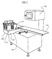
- FIG 2 illustrates a card assembly station situated adjacent to the product line.
- the card assembly station comprises a top portion 222 and a bottom portion 224.
- the top portion 222 as illustrated in Figure 3 , comprises a hopper 210 surrounded by a hopper guard 214.
- the hopper guard 214 encloses at least a portion of the hopper 210, and provides support for the hopper.
- the hopper is defined by four corner panels 212 arranged in accordance with the dimensions of the cards being dispensed from the hopper 210.
- Support fingers 216 at the bottom of the hopper releasably hold and support the cards until they are ready to be removed from the hopper 210.
- FIG. 4 illustrates a top view of an empty hopper 210, with suction cups 220 situated below.
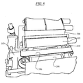
- Figure 5 illustrates the separation of the top portion 222 of the card assembly station from the bottom portion 224 of the card assembly station.
- the top portion 222 is pivotally attached to a shaft 226, allowing the top portion to pivot away from the conveying surface, and away from bottom portion 224.
- the hopper guard 214 and bottom enclosure 218 forms a substantially continuous skirt which houses the hopper 210 and the suction cups 220. Pivoting the top portion 222 away from the bottom portion 224 allows the bottom portion, which is enclosed on the sides by bottom enclosure 218, to be accessible from above, as illustrated in Figure 5 .
- the suction cups 220 are situated within the bottom portion 224 of the card assembly station, as illustrated in Figure 6 .
- Figure 7 illustrates the suction cups connected to a rigid horizontal block 300.
- the suction cups are raised and lowered according to the upward and downward motion of the rigid horizontal block 300.
- the suction cups are raised from their resting height "X” a distance “R” to a height “Y,” allowing the suction cups 220 to come into contact with the bottom card (not shown) in the hopper 210.
- the suction cups 220 exert a negative pressure in order to attach the bottom card.
- the bottom card is removed from the hopper by lowering the suction cups 220.
- the support fingers 216 which comprise an inclined surface comprising a series of gradual ridges 217 along the side in contact with the card ( Figure 7 ). This gradual stepping down of the inclined ridges 217 works in conjunction with the flexible nature of the cards to allow the edges to decrease its bending as the card is gradually pulled in a downward direction from the hopper along the support fingers 216.
- the horizontal block 300 is attached to a central rod 310 by a fastener 311.
- Two guiding rods 340 are fixed to the block 300 on either side of the central rod 310.
- the raising and lowering of the horizontal block 300 is achieved by the upward and downward movement of the central rod 310 telescopically within a central tube 320.
- the central tube is situated within a T-shaped base member 330.
- the base-member 330 also comprises two channels within each of the arms of the T-shape, which extend through the entire depth of the arms.
- the guiding rods 340 are fitted through the channels, and move vertically with the movement of the horizontal block 300.
- the guiding rods 340 assist in keeping the horizontal block 300 from inadvertently pivoting around the central rod 310, and ensure that the movement of the horizontal block 300 is even within the same vertical plane.
- the central rod is connected at its base 324 to a double acting air cylinder 325, the top portion of which is nested within the bottom 326 of the T-shaped base member 330.
- the dual acting pneumatic cylinder comprises two air ports 327a, 327b which can alternately act as pressure air in or air bleed out, to actuate the upwards and downward motion of the central rod, and correspondingly the horizontal support block 300 on which the suction cups are attached.
- Each suction cup 220 is connected to a stem 321, which extends upward from the horizontal block 300.
- the stem 321 and the suction cup 220 are connected to form a central channel through which a negative pressure can be applied to create a vacuum.
- L shaped air channels 322 are situated on either side of the horizontal block 300 to allow for a negative air pressure flow generated by an external source, to flow through the suction cups 220 and stems 321 and through a channel formed within the block 300.
- the suction cups 220 Once the suction cups 220 have removed a card 344 from the hopper 210 by attaching to the card and lowering the card, the card is lowered until the suction cups 220 are in their resting position "X," as illustrated in Figure 7 .
- a portion of the edge of the card closest to the conveying surface rests on a bottom guiding strip 357, illustrated in Figures 4 and 5 , which helps guide the lateral movement of the card between a top guiding strip 356 and the bottom guiding strip 357 as the card is moved to a staging position beneath the conveying surface.
- Both the top guiding strip 356 and the bottom guiding strip 357 have curved lips 358, 359 at the edge first coming in contact with the card to facilitate reception of the card, as illustrated in Figure 5 .
- the suction cups 220 continue to hold the card in place until a card clamp 240 moves laterally along clamp carriage guide arms 246 from its card staging position beneath the conveying surface, towards the "receiving position," where an awaiting card is held by the suction cups 220.
- the card clamp comprising a top plate 241 and a bottom plate 242 as illustrated in Figure 6 , will close on a central portion of the awaiting card, simultaneously triggering the release of the card by the suction cups.
- the card clamp is mounted on a clamp carriage 230 which moves bi-directionally along clamp carriage guide arms 246.
- the clamp carriage 230 is preferably composed of plastic.
- Figure 6 illustrates a card clamp 240 which has just begun to move the card along the clamp carriage guide arms 246 towards the staging direction. A portion of the card 344 slides under the top guiding strip 356. The guiding strips 356, 357 help maintain the leading edge of the card 245 in alignment with the card nip roller area 350.
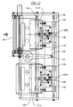
- Figure 12 shows the card clamp 240 in both the receiving position 240A and the staging position 240B.
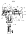
- a clamp carriage drive motor 270 ( Figure 13 ) rotates the clamp carriage drive arm 260 to move the clamp carriage 230 laterally along the clamp carriage guide arms 246 between the receiving position and the staging position ( Figure 12 ).
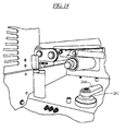
- the clamp carriage drive arm 260 pivots about a shaft 261, as illustrated in Figures 14 and 13 .
- the clamp carriage drive arm 260 pivots along an arc 550 which moves the clamp carriage along the clamp carriage guide arms 246 ( Figure 12 ).
- the pivotal motion of the clamp carriage drive arm 260 is transferred into a lateral movement through the use of a carriage bar 500 attached to the bottom of the clamp carriage 230, as shown in Figures 6 , 12 , and 13 .
- the carriage bar 500 is attached to the clamp carriage 230 using screws 501 as illustrated in Figures 15A and 15B .
- the carriage bar 500 comprises a groove 510 on the underside.
- the clamp carriage drive arm 260 comprises a pin 551 on the end of the arm.
- the pin 551 is of a size suitable for fitting into the groove 510, and slideably engaging with the groove.
- the pin 551 slides along the groove 510 in various positions.
- the pin 551 is a the position in the groove 510 farthest away from the card. This position is illustrated as 551 A in Figure 13 .
- the pin is situated at a position 551 B' or 551 B respectively, as illustrated by Figures 12 and 13 .
- FIGs 15A and 15B illustrates the clamping mechanism in detail.
- the top plate 241 is attached to a top plate strip 570 along the edge of top plate that is above the clamp carriage 230.
- the top plate strip is secured to the top plate 241 through the use of top plate screws 560 as illustrated in Figures 13 , 15A, and 15B .
- the bottom plate 242 is attached to the clamp carriage 230 through the use of bottom plate screws 561.
- the bottom plate extends beyond the clamping region 562 ( Figure 15 B) to cover an air chamber 580 formed in or bored into the clamp carriage 230.
- the air chamber 580 in the clamp carriage is a recessed portion in the clamp carriage 230 which contains a clamp piston 530.
- the bottom plate 242 covers an open top of the chamber 580.
- the clamp piston moves up and down in the air chamber 580 and is sealed to the air chamber sidewall by a seal ring 581, carried in a groove on the piston 530.
- the piston 530 is connected to the top plate strip 570 by a fastener 531 and a surrounding tubular spacer 532.
- the fastener 531 is threaded into a threaded hole in the top of the piston 530 and when drawn tight, clamps the tubular spacer between the strip 570 and the piston 530.
- the tubular spacer 532 slides within an annular air seal 533 carried by the bottom plate 242.
- Two air nozzles 540a, 540b are connected to bottom plate 242, and serve as alternate air inlet and outlet nozzles for the air chamber.
- the clamp piston moves upward as a result of pressurized air input into the nozzle 540b, with nozzle 540a acting as an air bleed, and moves downward to clamp a card as a result of pressurized air input into the nozzle 540a, with nozzle 540b acting as an air bleed.
- the nozzle 540a opens to a top side of the piston 530 within the chamber 580, and the nozzle 540b is open to a bottom side of the piston 530 within the air chamber 580, through a channel 540c.
- Two rod-shaped top clamp guides are attached to the top plate strip 570 on either side of the clamp piston 530. These clamp guides 520 are fitted through two channels 521 which span the entire depth of the clamp carriage 230. The clamp guides 520 assist in keeping the top plate from inadvertently pivoting around the clamp piston 530 or tilting from a true vertical movement.
- Figures 8 and 15 illustrate the card in its staging position, where the leading edges of the card are positioned in the card nip roller area 350.
- the card nip roller area 350 comprises a motorized drive roller 351 and an idler roller 352.
- the dispensing mechanism activates, causing the card nip to close and grasp the card between the drive roller and the idler roller.
- a pneumatic cylinder actuator 353 presses the idler roller 352, by pivoting an idler roller- mounting lever, toward the drive roller 351, to pinch the card therebetween.
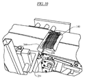
- the closing of the card nip is simultaneous with the card clamp releasing its hold on the card, thus allowing the card to roll up between adjacent conveying surfaces ( Figure 9 ), and to dispense beneath an oncoming sliced product ( Figure 10 ).
- the drive roller 351 is made of rubber or other gripping surface.
- the guide plate 254 is inclined upwards and in the direction of travel A, of the sliced product .
- the guide plate 254 assists in guiding the leading edge of the card upwards between adjacent conveying surfaces.
- a second guide plate 256 as illustrated in Figure 10 can be used for additional guidance of the card.
- the dispensing of the card is synchronized with the movement of oncoming sliced product such that the movement of the sliced product along the conveying surface allows the product draft to be deposited on the card as it emerges from between the adjacent conveying surfaces.
- the sliced product deposited on the dispensed card then continues down the conveying surface for further processing, such as packaging.
- a sliced product moves along the infeed conveyor and passes under the product grading station 100.
- the product grading station comprises a product sensor 120 which notes the position of the sliced product 140 on the conveying surface so as to allow the product to be tracked as it moves along the conveying surface ( Figure 1 ).
- the product sensor 120 After the sliced product passes the product sensor 120, it enters the photo area, designated as "B" in Figure 1 .
- a camera 110 captures a digital image of the sliced product.
- the digital image of the sliced product is transferred to a vision system software for analysis.
- the vision software such as the one disclosed in U.S.
- Patent 6,997,089 analyzes the captured image by comparing the lighter areas indicating fat, with the darker, lean areas of the sliced product.
- a fat-to-lean ratio is determined, and compared with a operator programmed fat-to-lean parameter to determine under which grade the sliced product being analyzed should be categorized, for example, grade 1 or grade 2.
- more than two different grades of sliced product can be sorted and disposed on appropriate cards with labeling information corresponding to the grade of the sliced product, in accordance with the invention.
- a signal is sent to the card assembly with the cards having labeling information corresponding to the grade of the particular sliced product, to activate the dispensing mechanism.
- the card assembly station(s) with cards that are inapplicable to the grade of the particular sliced product remains dormant and does not dispense a card between the conveying surface.
- the sliced product by-passes the inapplicable card assembly station(s) without incident, and thus is only deposited on the appropriate card dispensed between the conveying surfaces at the card assembly station dispensing cards with the applicable grade information.
- the sliced product can by-pass a dormant first assembly station, and be deposited on the card dispensed by the activated second assembly station.
- the sliced product can be deposited on a card dispensed by any one of the three card assembly stations that is activated to move the card from its staging position to being dispensed, while by-passing the other dormant card assembly stations with cards of inapplicable grades positioned in the staging station, waiting for the appropriate grade signal to activate their dispensing mechanism.
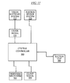
- Figure 11 is a schematic block diagram of one embodiment of a control system that may be used with the card dispenser.
- Figure 11 illustrates a central controller 900 which receives a signal from the position sensor system 920 used in conjunction with the product sensor 120.
- the central controller 900 also receives a grade signal 930 from the vision software system 910.
- the central controller 900 Upon receiving the grade signal 930, the central controller 900 sends a signal to the appropriate dispensing mechanism 960 to activate it.
- the controller simultaneously activates the dispensing system 960 which causes the card nip to close, by the pneumatic actuator 353, and sends a clamp signal 950 to the card clamp 240 to release so the card can be dispensed.
- the card clamp 240 releases the card to the card nip, the card clamp is sent back to the receiving position to receive the next card.
- a signal 940 is sent to the suction cups to move up and pull down the next card in the hopper, so that the card is already awaiting the card claim 240 when it returns to its sliding position.
- the central controller 900 sends a signal to close the clamp around the card, and simultaneously triggers a release of the suction force.
- the card clamp proceeds towards the staging position, and waits for the next activation signal of the dispensing mechanism.
Landscapes
- Engineering & Computer Science (AREA)
- Mechanical Engineering (AREA)
- Life Sciences & Earth Sciences (AREA)
- Wood Science & Technology (AREA)
- Zoology (AREA)
- Food Science & Technology (AREA)
- Credit Cards Or The Like (AREA)
- Sheets, Magazines, And Separation Thereof (AREA)
Applications Claiming Priority (3)
| Application Number | Priority Date | Filing Date | Title |
|---|---|---|---|
| US25508709P | 2009-10-26 | 2009-10-26 | |
| US25544509P | 2009-10-27 | 2009-10-27 | |
| PCT/US2010/054156 WO2011056603A1 (en) | 2009-10-26 | 2010-10-26 | Method and apparatus for a card dispsenser |
Publications (3)
| Publication Number | Publication Date |
|---|---|
| EP2493765A1 EP2493765A1 (en) | 2012-09-05 |
| EP2493765A4 EP2493765A4 (en) | 2013-11-27 |
| EP2493765B1 true EP2493765B1 (en) | 2014-10-15 |
Family
ID=43970264
Family Applications (1)
| Application Number | Title | Priority Date | Filing Date |
|---|---|---|---|
| EP10828864.8A Not-in-force EP2493765B1 (en) | 2009-10-26 | 2010-10-26 | Method and apparatus for a card dispenser |
Country Status (6)
| Country | Link |
|---|---|
| US (2) | US8740541B2 (da) |
| EP (1) | EP2493765B1 (da) |
| CA (2) | CA2778724C (da) |
| DK (1) | DK2493765T3 (da) |
| ES (1) | ES2527227T3 (da) |
| WO (1) | WO2011056603A1 (da) |
Cited By (1)
| Publication number | Priority date | Publication date | Assignee | Title |
|---|---|---|---|---|
| US12311567B2 (en) | 2021-10-25 | 2025-05-27 | Provisur Technologies, Inc. | Releasable side strapping assembly for a food product slicing apparatus |
Families Citing this family (12)
| Publication number | Priority date | Publication date | Assignee | Title |
|---|---|---|---|---|
| DK2493765T3 (da) * | 2009-10-26 | 2015-01-19 | Formax Inc | Fremgangsmåde og apparat til en kartondispenser |
| DE102011110690B4 (de) | 2011-08-16 | 2015-03-05 | Weber Maschinenbau Gmbh Breidenbach | Verfahren zum Zuordnen von Produktträgern und Lebensmittelverarbeitungsvorrichtung |
| CN103824095B (zh) * | 2012-11-16 | 2017-03-01 | 财团法人金属工业研究发展中心 | 多匣式卡片传送装置 |
| EP3315309B1 (en) * | 2016-10-31 | 2021-08-04 | HP Scitex Ltd | Vacuum within a pallet conveyor for a printing system |
| CN106882406B (zh) * | 2017-03-20 | 2023-05-26 | 深圳市金石智控股份有限公司 | U盘自动摆盘机 |
| CN108750580A (zh) * | 2018-07-18 | 2018-11-06 | 苏州巨通自动化设备有限公司 | 一种座椅下料机 |
| CN110844562A (zh) * | 2019-11-19 | 2020-02-28 | 北京石晶光电科技股份有限公司 | 一种送料滑台 |
| CN112520427B (zh) * | 2020-11-09 | 2023-03-28 | 宁波阅荷思山智能科技有限公司 | 一种磁控式精密防磨损卡片送料装置 |
| DE102022121774A1 (de) * | 2022-08-29 | 2024-02-29 | Multivac Sepp Haggenmüller Se & Co. Kg | Verfahren zum automatischen Einhalten einer vorgegebenen Portions-Anordnung in einer Tray-Mulde sowie hierfür geeignete Verpackungs-Vorrichtung |
| US12384635B2 (en) * | 2023-05-04 | 2025-08-12 | Automation, Inc. | Adjustable tray stacker/destacker assembly |
| WO2024231482A1 (en) | 2023-05-09 | 2024-11-14 | Weber Food Technology Gmbh | Card dispensing apparatus |
| DE102023124771A1 (de) | 2023-05-09 | 2024-11-14 | Weber Food Technology Gmbh | Kartenzuführvorrichtung |
Family Cites Families (36)
| Publication number | Priority date | Publication date | Assignee | Title |
|---|---|---|---|---|
| US2304146A (en) * | 1940-07-19 | 1942-12-08 | Standard Cap & Seal Corp | Feeding and serving mechanism |
| US2975576A (en) * | 1955-06-02 | 1961-03-21 | Wilson & Co Inc | Selective card dispensing tray |
| US2907152A (en) | 1956-12-20 | 1959-10-06 | Swift & Co | Method and machine for use in packaging of bacon or the like |
| US3051581A (en) * | 1959-01-02 | 1962-08-28 | Swift & Co | Method and apparatus for packaging food |
| US3137981A (en) * | 1961-01-16 | 1964-06-23 | Lynch Corp | Multiple magazine for cartoning machine |
| US3105337A (en) | 1961-04-05 | 1963-10-01 | Lynch Corp | Product feeder for cartoning machine |
| US3155244A (en) * | 1962-09-19 | 1964-11-03 | Standard Oil Co | Sheet feeding and manipulating device and misfeed detector means therefor |
| US3269082A (en) * | 1963-04-15 | 1966-08-30 | Swift & Co | Method and apparatus for feeding blanks to package sliced product |
| US3405504A (en) * | 1965-10-21 | 1968-10-15 | Chemetron Corp | Transferring system |
| US3455083A (en) * | 1966-06-27 | 1969-07-15 | Dohm & Nelke Inc | Boarding machines |
| US3523400A (en) * | 1967-10-02 | 1970-08-11 | Jones & Co Inc R A | Leaflet feeder and inserter for cartoners |
| US3815319A (en) | 1973-03-21 | 1974-06-11 | Mayer & Co Inc O | Means and method for unfolding bacon board flaps and the like |
| US3846958A (en) * | 1973-10-10 | 1974-11-12 | Cashin Systems Corp | Apparatus for weighing and segregating sliced bacon from a slicing machine |
| IT1000889B (it) * | 1973-11-21 | 1976-04-10 | Gd Spa | Dispositivo per sfal dare pile di fogli particolarmente sbozzati o fustellati di cartoncino e simili da alimentare singolarmente a mac chine condizionatrici di sigarette in pacchetti del tipo con coperchio incernierato |
| US4065911A (en) * | 1976-07-12 | 1978-01-03 | Amtron, Division Of The Sippican Corporation | Baconweigher |
| US4328657A (en) | 1980-04-24 | 1982-05-11 | Cashin Systems Corp. | Automatic card dispenser and pick-off assembly |
| US4452031A (en) * | 1980-04-24 | 1984-06-05 | Cashin Systems Corp. | Automatic card dispenser and pick-off assembly |
| US4728092A (en) | 1986-03-21 | 1988-03-01 | Astro Machine Corporation | Suction control system for suction cup sheet feeding apparatus |
| US4894976A (en) | 1988-08-25 | 1990-01-23 | Amca International Corporation | Missing card circuit for a slicing machine |
| IT1251149B (it) * | 1991-08-05 | 1995-05-04 | Sitma Spa | Dispositivo di alimentazione di fogli singoli o similari ad una macchina confezionatrice, etichettatrice od imbustatrice |
| US5443150A (en) | 1993-09-23 | 1995-08-22 | Rapidpak, Inc. | Apparatus for advancing preformed containers |
| JPH07315574A (ja) * | 1994-05-26 | 1995-12-05 | Okura Yusoki Co Ltd | ピッキング装置 |
| DE19710236B4 (de) * | 1996-03-20 | 2008-01-03 | Giesecke & Devrient Gmbh | Vorrichtung zum Bearbeiten von flachen, flexiblen Gegenständen, wie z. B. Karten aus Kunststoff oder Papier |
| IT1294186B1 (it) * | 1997-09-04 | 1999-03-22 | Gd Spa | Metodo ed unita' di alimentazione di sbozzati ad una macchina utilizzatrice |
| DE19914707A1 (de) * | 1999-03-31 | 2000-10-05 | Biforce Anstalt Vaduz | Verfahren und Vorrichtung zum Aufschneiden von Lebensmittelprodukten |
| DE19918527A1 (de) * | 1999-04-23 | 2000-10-26 | Iwk Verpackungstechnik Gmbh | Verpackungsmaschine |
| US6263640B1 (en) * | 1999-07-13 | 2001-07-24 | Hormel Foods, Llc | Bacon board dispenser |
| DE10034140C2 (de) * | 2000-07-13 | 2003-01-02 | Uhlmann Pac Systeme Gmbh & Co | Magazinvorrichtung für Faltschachteln bei Verpackungsmaschinen |
| US6993887B2 (en) * | 2000-08-07 | 2006-02-07 | Dsd Communications, Inc. | System and method for including packets with goods during automated packaging |
| US6997089B2 (en) | 2002-06-25 | 2006-02-14 | Formax, Inc. | Optical grading system for slicer apparatus |
| JP4423368B2 (ja) | 2003-12-19 | 2010-03-03 | 旭精工株式会社 | カード状商品の自動払出装置およびその方法 |
| US7934718B2 (en) * | 2005-03-24 | 2011-05-03 | Xerox Corporation | Sheet feeding of faster rate printing systems with plural slower rate sheet feeders |
| US7513432B2 (en) | 2006-07-11 | 2009-04-07 | International Currency Technologies Corporation | Card dispenser adjustable subject to the size of the cards to be dispensed |
| CA2779330A1 (en) * | 2009-10-26 | 2011-05-12 | Formax Inc. | Method and apparatus for weighing sliced food products |
| DK2493765T3 (da) * | 2009-10-26 | 2015-01-19 | Formax Inc | Fremgangsmåde og apparat til en kartondispenser |
| TWI466065B (zh) * | 2010-07-23 | 2014-12-21 | Hon Hai Prec Ind Co Ltd | 偵測裝置及偵測方法 |
-
2010
- 2010-10-26 DK DK10828864.8T patent/DK2493765T3/da active
- 2010-10-26 EP EP10828864.8A patent/EP2493765B1/en not_active Not-in-force
- 2010-10-26 CA CA2778724A patent/CA2778724C/en not_active Expired - Fee Related
- 2010-10-26 US US13/504,036 patent/US8740541B2/en active Active
- 2010-10-26 ES ES10828864.8T patent/ES2527227T3/es active Active
- 2010-10-26 CA CA3013395A patent/CA3013395A1/en not_active Abandoned
- 2010-10-26 WO PCT/US2010/054156 patent/WO2011056603A1/en not_active Ceased
-
2014
- 2014-04-03 US US14/244,263 patent/US10384889B2/en active Active
Cited By (5)
| Publication number | Priority date | Publication date | Assignee | Title |
|---|---|---|---|---|
| US12311567B2 (en) | 2021-10-25 | 2025-05-27 | Provisur Technologies, Inc. | Releasable side strapping assembly for a food product slicing apparatus |
| US12427687B2 (en) | 2021-10-25 | 2025-09-30 | Provisur Technologies, Inc. | Profile scanner and feed assembly for a high-speed food slicing apparatus |
| US12441021B2 (en) | 2021-10-25 | 2025-10-14 | Provisur Technologies, Inc. | Blade assembly and counterweight mechanism for a high-speed food slicing apparatus, and methods associated with the same |
| US12558808B2 (en) | 2021-10-25 | 2026-02-24 | Provisur Technologies, Inc. | Blade assembly and retraction mechanism for a high-speed food slicing apparatus |
| US12570021B2 (en) | 2021-10-25 | 2026-03-10 | Provisur Technologies, Inc. | Drive assembly for a food product slicing apparatus |
Also Published As
| Publication number | Publication date |
|---|---|
| CA2778724C (en) | 2018-09-04 |
| US10384889B2 (en) | 2019-08-20 |
| WO2011056603A1 (en) | 2011-05-12 |
| EP2493765A1 (en) | 2012-09-05 |
| US20120207578A1 (en) | 2012-08-16 |
| ES2527227T3 (es) | 2015-01-21 |
| CA2778724A1 (en) | 2011-05-12 |
| EP2493765A4 (en) | 2013-11-27 |
| DK2493765T3 (da) | 2015-01-19 |
| US8740541B2 (en) | 2014-06-03 |
| CA3013395A1 (en) | 2011-05-12 |
| US20140212255A1 (en) | 2014-07-31 |
Similar Documents
| Publication | Publication Date | Title |
|---|---|---|
| EP2493765B1 (en) | Method and apparatus for a card dispenser | |
| US5203953A (en) | Process and apparatus for conveying labels to be transferred to a (cigarette) pack | |
| AU2002358360B2 (en) | Pack opening apparatus and method | |
| US9272804B2 (en) | Bundle unwrapping machine | |
| US9663320B2 (en) | Method and machine for forming bag packs | |
| CA2300183C (en) | Feeding machine | |
| US5478428A (en) | Label separator and method for separating a label from a backing | |
| US4365458A (en) | Method and apparatus for filling sleeves with finished disc records and inserting the filled sleeves into jackets | |
| US5417794A (en) | Apparatus for simultaneously disposing tubular labels on a plurality of bottles or other containers | |
| GB2027666A (en) | Method and apparatus for bundling sheets of thin material for example banknotes with tape | |
| US5275524A (en) | Apparatus for cutting and removing package material | |
| DK160928B (da) | Apparat til automatisk fyldning af en pose | |
| US5056202A (en) | Apparatus for making and transporting stacks of foil sections | |
| JPH0199909A (ja) | パッケージ包装方法及び機械 | |
| US4926616A (en) | Cassette packaging system | |
| US6544158B2 (en) | High speed feeding apparatus for clamshell die cutter | |
| CN114735310A (zh) | 一种锯链自动包装生产线及包装工艺 | |
| US5116040A (en) | Sheet-feeder | |
| US6241233B1 (en) | Stack forming and removing apparatus with undersheet placement | |
| JPH0977119A (ja) | 缶詰用キャップ装着装置 | |
| EP0132862B1 (en) | A device for identification of cheese by applying printed matter | |
| JPS61155120A (ja) | コンベヤ | |
| CN109367850B (zh) | 一种杯装饮品压盖机 | |
| US4977726A (en) | Continuous signature stacker machine provided with special device for transversely ejecting the assembled package | |
| CN218662729U (zh) | 一种锯链自动包装线 |
Legal Events
| Date | Code | Title | Description |
|---|---|---|---|
| PUAI | Public reference made under article 153(3) epc to a published international application that has entered the european phase |
Free format text: ORIGINAL CODE: 0009012 |
|
| 17P | Request for examination filed |
Effective date: 20120523 |
|
| AK | Designated contracting states |
Kind code of ref document: A1 Designated state(s): AL AT BE BG CH CY CZ DE DK EE ES FI FR GB GR HR HU IE IS IT LI LT LU LV MC MK MT NL NO PL PT RO RS SE SI SK SM TR |
|
| DAX | Request for extension of the european patent (deleted) | ||
| A4 | Supplementary search report drawn up and despatched |
Effective date: 20131028 |
|
| RIC1 | Information provided on ipc code assigned before grant |
Ipc: B65B 25/06 20060101ALI20131022BHEP Ipc: B65B 59/00 20060101ALI20131022BHEP Ipc: B65B 57/00 20060101ALI20131022BHEP Ipc: B65B 43/18 20060101AFI20131022BHEP |
|
| REG | Reference to a national code |
Ref country code: DE Ref legal event code: R079 Ref document number: 602010019620 Country of ref document: DE Free format text: PREVIOUS MAIN CLASS: B65B0043180000 Ipc: A22C0017100000 |
|
| GRAP | Despatch of communication of intention to grant a patent |
Free format text: ORIGINAL CODE: EPIDOSNIGR1 |
|
| RIC1 | Information provided on ipc code assigned before grant |
Ipc: B65B 43/18 20060101ALI20140430BHEP Ipc: B65B 59/00 20060101ALI20140430BHEP Ipc: B65B 57/00 20060101ALI20140430BHEP Ipc: A22C 17/10 20060101AFI20140430BHEP Ipc: B65B 25/06 20060101ALI20140430BHEP |
|
| INTG | Intention to grant announced |
Effective date: 20140516 |
|
| GRAS | Grant fee paid |
Free format text: ORIGINAL CODE: EPIDOSNIGR3 |
|
| GRAA | (expected) grant |
Free format text: ORIGINAL CODE: 0009210 |
|
| AK | Designated contracting states |
Kind code of ref document: B1 Designated state(s): AL AT BE BG CH CY CZ DE DK EE ES FI FR GB GR HR HU IE IS IT LI LT LU LV MC MK MT NL NO PL PT RO RS SE SI SK SM TR |
|
| REG | Reference to a national code |
Ref country code: CH Ref legal event code: EP Ref country code: GB Ref legal event code: FG4D |
|
| REG | Reference to a national code |
Ref country code: IE Ref legal event code: FG4D |
|
| REG | Reference to a national code |
Ref country code: AT Ref legal event code: REF Ref document number: 691218 Country of ref document: AT Kind code of ref document: T Effective date: 20141115 |
|
| REG | Reference to a national code |
Ref country code: DE Ref legal event code: R096 Ref document number: 602010019620 Country of ref document: DE Effective date: 20141127 |
|
| REG | Reference to a national code |
Ref country code: DK Ref legal event code: T3 Effective date: 20150115 |
|
| REG | Reference to a national code |
Ref country code: ES Ref legal event code: FG2A Ref document number: 2527227 Country of ref document: ES Kind code of ref document: T3 Effective date: 20150121 |
|
| REG | Reference to a national code |
Ref country code: NL Ref legal event code: T3 |
|
| REG | Reference to a national code |
Ref country code: AT Ref legal event code: MK05 Ref document number: 691218 Country of ref document: AT Kind code of ref document: T Effective date: 20141015 |
|
| REG | Reference to a national code |
Ref country code: LT Ref legal event code: MG4D |
|
| PG25 | Lapsed in a contracting state [announced via postgrant information from national office to epo] |
Ref country code: FI Free format text: LAPSE BECAUSE OF FAILURE TO SUBMIT A TRANSLATION OF THE DESCRIPTION OR TO PAY THE FEE WITHIN THE PRESCRIBED TIME-LIMIT Effective date: 20141015 Ref country code: LT Free format text: LAPSE BECAUSE OF FAILURE TO SUBMIT A TRANSLATION OF THE DESCRIPTION OR TO PAY THE FEE WITHIN THE PRESCRIBED TIME-LIMIT Effective date: 20141015 Ref country code: IS Free format text: LAPSE BECAUSE OF FAILURE TO SUBMIT A TRANSLATION OF THE DESCRIPTION OR TO PAY THE FEE WITHIN THE PRESCRIBED TIME-LIMIT Effective date: 20150215 Ref country code: PT Free format text: LAPSE BECAUSE OF FAILURE TO SUBMIT A TRANSLATION OF THE DESCRIPTION OR TO PAY THE FEE WITHIN THE PRESCRIBED TIME-LIMIT Effective date: 20150216 Ref country code: NO Free format text: LAPSE BECAUSE OF FAILURE TO SUBMIT A TRANSLATION OF THE DESCRIPTION OR TO PAY THE FEE WITHIN THE PRESCRIBED TIME-LIMIT Effective date: 20150115 |
|
| PG25 | Lapsed in a contracting state [announced via postgrant information from national office to epo] |
Ref country code: SE Free format text: LAPSE BECAUSE OF FAILURE TO SUBMIT A TRANSLATION OF THE DESCRIPTION OR TO PAY THE FEE WITHIN THE PRESCRIBED TIME-LIMIT Effective date: 20141015 Ref country code: PL Free format text: LAPSE BECAUSE OF FAILURE TO SUBMIT A TRANSLATION OF THE DESCRIPTION OR TO PAY THE FEE WITHIN THE PRESCRIBED TIME-LIMIT Effective date: 20141015 Ref country code: CY Free format text: LAPSE BECAUSE OF FAILURE TO SUBMIT A TRANSLATION OF THE DESCRIPTION OR TO PAY THE FEE WITHIN THE PRESCRIBED TIME-LIMIT Effective date: 20141015 Ref country code: RS Free format text: LAPSE BECAUSE OF FAILURE TO SUBMIT A TRANSLATION OF THE DESCRIPTION OR TO PAY THE FEE WITHIN THE PRESCRIBED TIME-LIMIT Effective date: 20141015 Ref country code: LV Free format text: LAPSE BECAUSE OF FAILURE TO SUBMIT A TRANSLATION OF THE DESCRIPTION OR TO PAY THE FEE WITHIN THE PRESCRIBED TIME-LIMIT Effective date: 20141015 Ref country code: AT Free format text: LAPSE BECAUSE OF FAILURE TO SUBMIT A TRANSLATION OF THE DESCRIPTION OR TO PAY THE FEE WITHIN THE PRESCRIBED TIME-LIMIT Effective date: 20141015 Ref country code: HR Free format text: LAPSE BECAUSE OF FAILURE TO SUBMIT A TRANSLATION OF THE DESCRIPTION OR TO PAY THE FEE WITHIN THE PRESCRIBED TIME-LIMIT Effective date: 20141015 Ref country code: GR Free format text: LAPSE BECAUSE OF FAILURE TO SUBMIT A TRANSLATION OF THE DESCRIPTION OR TO PAY THE FEE WITHIN THE PRESCRIBED TIME-LIMIT Effective date: 20150116 |
|
| REG | Reference to a national code |
Ref country code: CH Ref legal event code: PL |
|
| PG25 | Lapsed in a contracting state [announced via postgrant information from national office to epo] |
Ref country code: BE Free format text: LAPSE BECAUSE OF NON-PAYMENT OF DUE FEES Effective date: 20141031 |
|
| REG | Reference to a national code |
Ref country code: DE Ref legal event code: R097 Ref document number: 602010019620 Country of ref document: DE |
|
| REG | Reference to a national code |
Ref country code: IE Ref legal event code: MM4A |
|
| PG25 | Lapsed in a contracting state [announced via postgrant information from national office to epo] |
Ref country code: MC Free format text: LAPSE BECAUSE OF FAILURE TO SUBMIT A TRANSLATION OF THE DESCRIPTION OR TO PAY THE FEE WITHIN THE PRESCRIBED TIME-LIMIT Effective date: 20141015 Ref country code: RO Free format text: LAPSE BECAUSE OF FAILURE TO SUBMIT A TRANSLATION OF THE DESCRIPTION OR TO PAY THE FEE WITHIN THE PRESCRIBED TIME-LIMIT Effective date: 20141015 Ref country code: LI Free format text: LAPSE BECAUSE OF NON-PAYMENT OF DUE FEES Effective date: 20141031 Ref country code: SK Free format text: LAPSE BECAUSE OF FAILURE TO SUBMIT A TRANSLATION OF THE DESCRIPTION OR TO PAY THE FEE WITHIN THE PRESCRIBED TIME-LIMIT Effective date: 20141015 Ref country code: CZ Free format text: LAPSE BECAUSE OF FAILURE TO SUBMIT A TRANSLATION OF THE DESCRIPTION OR TO PAY THE FEE WITHIN THE PRESCRIBED TIME-LIMIT Effective date: 20141015 Ref country code: CH Free format text: LAPSE BECAUSE OF NON-PAYMENT OF DUE FEES Effective date: 20141031 Ref country code: EE Free format text: LAPSE BECAUSE OF FAILURE TO SUBMIT A TRANSLATION OF THE DESCRIPTION OR TO PAY THE FEE WITHIN THE PRESCRIBED TIME-LIMIT Effective date: 20141015 |
|
| PLBE | No opposition filed within time limit |
Free format text: ORIGINAL CODE: 0009261 |
|
| STAA | Information on the status of an ep patent application or granted ep patent |
Free format text: STATUS: NO OPPOSITION FILED WITHIN TIME LIMIT |
|
| 26N | No opposition filed |
Effective date: 20150716 |
|
| REG | Reference to a national code |
Ref country code: FR Ref legal event code: PLFP Year of fee payment: 6 |
|
| PG25 | Lapsed in a contracting state [announced via postgrant information from national office to epo] |
Ref country code: IE Free format text: LAPSE BECAUSE OF NON-PAYMENT OF DUE FEES Effective date: 20141026 |
|
| PG25 | Lapsed in a contracting state [announced via postgrant information from national office to epo] |
Ref country code: SI Free format text: LAPSE BECAUSE OF FAILURE TO SUBMIT A TRANSLATION OF THE DESCRIPTION OR TO PAY THE FEE WITHIN THE PRESCRIBED TIME-LIMIT Effective date: 20141015 |
|
| PG25 | Lapsed in a contracting state [announced via postgrant information from national office to epo] |
Ref country code: SM Free format text: LAPSE BECAUSE OF FAILURE TO SUBMIT A TRANSLATION OF THE DESCRIPTION OR TO PAY THE FEE WITHIN THE PRESCRIBED TIME-LIMIT Effective date: 20141015 |
|
| PG25 | Lapsed in a contracting state [announced via postgrant information from national office to epo] |
Ref country code: BG Free format text: LAPSE BECAUSE OF FAILURE TO SUBMIT A TRANSLATION OF THE DESCRIPTION OR TO PAY THE FEE WITHIN THE PRESCRIBED TIME-LIMIT Effective date: 20141015 |
|
| PG25 | Lapsed in a contracting state [announced via postgrant information from national office to epo] |
Ref country code: TR Free format text: LAPSE BECAUSE OF FAILURE TO SUBMIT A TRANSLATION OF THE DESCRIPTION OR TO PAY THE FEE WITHIN THE PRESCRIBED TIME-LIMIT Effective date: 20141015 Ref country code: HU Free format text: LAPSE BECAUSE OF FAILURE TO SUBMIT A TRANSLATION OF THE DESCRIPTION OR TO PAY THE FEE WITHIN THE PRESCRIBED TIME-LIMIT; INVALID AB INITIO Effective date: 20101026 Ref country code: MT Free format text: LAPSE BECAUSE OF FAILURE TO SUBMIT A TRANSLATION OF THE DESCRIPTION OR TO PAY THE FEE WITHIN THE PRESCRIBED TIME-LIMIT Effective date: 20141015 Ref country code: LU Free format text: LAPSE BECAUSE OF NON-PAYMENT OF DUE FEES Effective date: 20141026 |
|
| REG | Reference to a national code |
Ref country code: FR Ref legal event code: PLFP Year of fee payment: 7 |
|
| REG | Reference to a national code |
Ref country code: FR Ref legal event code: PLFP Year of fee payment: 8 |
|
| PG25 | Lapsed in a contracting state [announced via postgrant information from national office to epo] |
Ref country code: MK Free format text: LAPSE BECAUSE OF FAILURE TO SUBMIT A TRANSLATION OF THE DESCRIPTION OR TO PAY THE FEE WITHIN THE PRESCRIBED TIME-LIMIT Effective date: 20141015 |
|
| REG | Reference to a national code |
Ref country code: FR Ref legal event code: PLFP Year of fee payment: 9 |
|
| PG25 | Lapsed in a contracting state [announced via postgrant information from national office to epo] |
Ref country code: AL Free format text: LAPSE BECAUSE OF FAILURE TO SUBMIT A TRANSLATION OF THE DESCRIPTION OR TO PAY THE FEE WITHIN THE PRESCRIBED TIME-LIMIT Effective date: 20141015 |
|
| PGFP | Annual fee paid to national office [announced via postgrant information from national office to epo] |
Ref country code: NL Payment date: 20181026 Year of fee payment: 9 |
|
| PGFP | Annual fee paid to national office [announced via postgrant information from national office to epo] |
Ref country code: DK Payment date: 20181029 Year of fee payment: 9 Ref country code: DE Payment date: 20181029 Year of fee payment: 9 |
|
| PGFP | Annual fee paid to national office [announced via postgrant information from national office to epo] |
Ref country code: ES Payment date: 20181102 Year of fee payment: 9 Ref country code: IT Payment date: 20181023 Year of fee payment: 9 Ref country code: GB Payment date: 20181029 Year of fee payment: 9 Ref country code: FR Payment date: 20181025 Year of fee payment: 9 |
|
| REG | Reference to a national code |
Ref country code: DE Ref legal event code: R119 Ref document number: 602010019620 Country of ref document: DE |
|
| REG | Reference to a national code |
Ref country code: DK Ref legal event code: EBP Effective date: 20191031 |
|
| REG | Reference to a national code |
Ref country code: NL Ref legal event code: MM Effective date: 20191101 |
|
| PG25 | Lapsed in a contracting state [announced via postgrant information from national office to epo] |
Ref country code: DE Free format text: LAPSE BECAUSE OF NON-PAYMENT OF DUE FEES Effective date: 20200501 |
|
| PG25 | Lapsed in a contracting state [announced via postgrant information from national office to epo] |
Ref country code: NL Free format text: LAPSE BECAUSE OF NON-PAYMENT OF DUE FEES Effective date: 20191101 |
|
| GBPC | Gb: european patent ceased through non-payment of renewal fee |
Effective date: 20191026 |
|
| PG25 | Lapsed in a contracting state [announced via postgrant information from national office to epo] |
Ref country code: DK Free format text: LAPSE BECAUSE OF NON-PAYMENT OF DUE FEES Effective date: 20191031 Ref country code: IT Free format text: LAPSE BECAUSE OF NON-PAYMENT OF DUE FEES Effective date: 20191026 Ref country code: FR Free format text: LAPSE BECAUSE OF NON-PAYMENT OF DUE FEES Effective date: 20191031 Ref country code: GB Free format text: LAPSE BECAUSE OF NON-PAYMENT OF DUE FEES Effective date: 20191026 |
|
| REG | Reference to a national code |
Ref country code: ES Ref legal event code: FD2A Effective date: 20210526 |
|
| PG25 | Lapsed in a contracting state [announced via postgrant information from national office to epo] |
Ref country code: ES Free format text: LAPSE BECAUSE OF NON-PAYMENT OF DUE FEES Effective date: 20191027 |
|
| P01 | Opt-out of the competence of the unified patent court (upc) registered |
Effective date: 20230425 |